物料型号:
- 型号:G3VM-41GR5
器件简介:
- G3VM-41GR5是一款新型MOS FET继电器,具有低输出电容(CR = 10pF)和导通电阻(ON resistance of 1Ω,典型值),适用于40V负载电压模型。
引脚分配:
- 接触形式:SPST-NO(单刀单掷-常开)
- 封装类型:表面贴装端子
参数特性:
- 输入LED正向电流:50mA
- 输入LED反向电压:5V
- 输出介质强度:40V
- 连续负载电流:300mA
- 导通时的最大电阻(RON):1.0Ω(典型值)
- 继电器开启时的漏电流:1.0nA(最大值)
- 输入和输出之间的介质强度:1500Vrms(交流电,1分钟)
功能详解:
- 该继电器具有低输出电容和低导通电阻,有助于减少输出信号的衰减。
- 最大漏电流为1.0nA,当输出继电器处于开启状态时。
应用信息:
- 半导体检测工具
- 测量设备
- 宽带系统
- 数据记录器
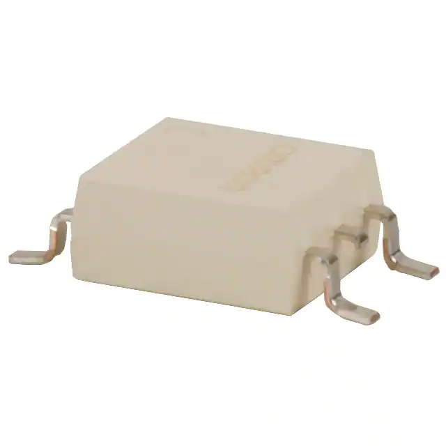
封装信息:
- 封装类型:表面贴装
- 尺寸:具体尺寸信息以毫米为单位,详见PDF文档中的图表。