G3VM-41LR5
MOS FET Relays
World’s Smallest * SSOP Package MOS
FET Relays with Low Output Capacitance
and ON Resistance (C × R = 10 pF • Ω)
in a 40-V Load Voltage Model.
• ON resistance of 1 Ω (typical) suppresses output signal attenuation.
* As of March 2011 Survey by OMRON
Note: The actual product is marked differently from the
image shown here.
RoHS compliant
■ Application Examples
■ Terminal Arrangement/Internal
Connections
• Semiconductor test equipment
• Test & Measurement equipment
416
• Communication equipment
Model name
OMRON mark
• Data loggers
LOT.No.
612
Note: The actual product is marked differently from the image shown here.
■ List of Models
Package type
Contact form
Load voltage
(peak value) *
Terminals
Model
Minimum package quantity
Number per tape and reel
G3VM-41LR5
SSOP4
1a
(SPST-NO)
Surface-mounting Terminals
40 V
-
G3VM-41LR5 (TR05)
500
G3VM-41LR5 (TR10)
1,000
G3VM-41LR5 (TR)
1,500
Note: Ask your OMRON representative for orders under 1,500 pcs, 1,000 pcs, or 500 pcs. We can supply products with the tape already cut.
Tape-cut SSOPs are packaged without humidity resistance. Use manual soldering to mount them.
Refer to common precautions.
* The AC peak and DC value are given for the load voltage.
■ Absolute Maximum Ratings (Ta = 25 °C)
Output
Input
Item
LED forward current
LED forward current reduction rate
LED reverse voltage
Connection temperature
Load voltage (AC peak/DC)
Continuous load current (AC peak/DC)
ON current reduction rate
Connection temperature
Dielectric strength between
I/O (See note 1.)
Ambient operating temperature
Ambient storage temperature
Soldering temperature
Symbol
IF
∆IF/°C
VR
TJ
VOFF
IO
∆IO/°C
TJ
Rating
50
−0.5
5
125
40
300
−3.0
125
Unit
mA
mA/°C
V
°C
V
mA
mA/°C
°C
VI-O
1500
Vrms
Ta
Tstg
-
−20 to +85
−40 to +125
260
°C
°C
°C
Measurement conditions
Ta ≥ 25 °C
Ta ≥ 25 °C
AC for 1 min
With no icing or condensation
With no icing or condensation
10 s
Note: 1. The dielectric strength between the input and
output was checked by applying voltage
between all pins as a group on the LED side and
all pins as a group on the light-receiving side.
■ Electrical Characteristics (Ta = 25 °C)
Output
Input
Item
Symbol Minimum Typical Maximum
LED forward voltage
VF
1.0
1.15
1.3
Reverse current
IR
10
Capacity between terminals
CT
15
Trigger LED forward current
IFT
4
Maximum resistance with output ON
RON
1.0
1.5
Current leakage when the relay is open
ILEAK
1.0
Capacity between terminals COFF
10
14
Capacity between I/O terminals
CI-O
0.8
Insulation resistance between I/O terminals
RI-O
1000
Turn-ON time
tON
0.2
0.5
Turn-OFF time
tOFF
0.2
0.5
1
Unit
V
µA
pF
mA
Ω
nA
pF
pF
MΩ
ms
ms
Measurement conditions
Note: 2. Turn-ON and Turn-OFF Times
IF = 10 mA
IF 1
VR = 5 V
4 RL
VDD
V = 0, f = 1 MHz
VOUT
2
3
IO = 100 mA
IF = 5 mA, IO = 300 mA, t = 10 ms
VOFF = 30 V, Ta = 50 °C
V = 0, f = 100 MHz, t < 1 s
IF
f = 1 MHz, VS = 0 V
VI-O = 500 VDC, ROH ≤ 60 %
90%
VOUT
10%
IF = 5 mA, RL = 200 Ω,
t ON
t OFF
VDD = 10 V (See note 2.)
�G3VM-41LR5
MOS FET Relays
■ Recommended Operating Conditions
Use the G3VM under the following conditions so that the Relay will operate properly.
Item
Symbol
Minimum
Typical
Maximum
Unit
Load voltage (AC peak/DC)
Operating LED forward current
Continuous load current (AC peak/DC)
Ambient operating temperature
VDD
IF
IO
Ta
10
25
-
32
30
300
60
V
mA
mA
°C
■ Engineering Data
LED forward current vs. Ambient temperature
Continuous load current vs. Ambient temperature
LED forward current vs. LED forward voltage
100
80
60
40
IF - VF
LED forward current IF (mA)
IO - Ta
Continuous load current IO (mA)
LED forward current IF (mA)
IF - Ta
500
400
300
200
Ta = 25 °C
50
30
10
5
3
1
0.5
100
20
100
0.3
0
0
-20
0
20
40
60
80
100
120
-20
0
20
Ambient temperature Ta (°C)
Continuous load current vs. On-state voltage
80
60
0
2
1.6
1.2
0.8
0.4
0.2
0
0.4
-20
0
20
On-state voltage VON (V)
Turn ON, Turn OFF time vs. LED forward current
30
tON
1
3
10
30
60
80
100
300
1.8
4
3
2
1
0
-20
100
0
20
VDD = 10 V,
RL = 200 Ω
IF = 10 mA
250
tOFF
200
150
80
100
Current leakage vs. Load voltage
15
Ta = 25 °C
10
5
tON
100
60
ILEAK - VOFF
350
300
40
Ambient temperature Ta (°C)
Current leakage ILEAK (pA)
tOFF
100
10
40
Turn ON, Turn OFF time vs. Ambient temperature
Turn ON, Turn OFF time tON, tOFF (µs)
Turn ON, Turn OFF time tON, tOFF (µs)
1000
1.6
IO = 100 mA
t
很抱歉,暂时无法提供与“G3VM-41LR5”相匹配的价格&库存,您可以联系我们找货
免费人工找货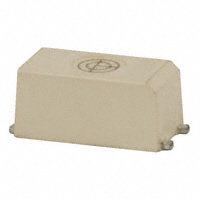


 工商网监
湘ICP备2023018690号
工商网监
湘ICP备2023018690号
