s08b_smartslice.fm Page 131 Monday, December 19, 2011 3:45 PM
GRT1-@
System Configuration
SmartSlice I/O
Plug-and-Play I/O
Machine Automation Controller
Remote I/O with digital and analogue I/O units, relay
outputs and configurable temperature inputs. All
SmartSlice units feature screwless ‘push-in’ I/O wiring,
detachable I/O connector, and hot-swap capability. The
EtherCAT ‘coupler’ automatically scans the connected I/O
units at startup. The NJ-Series controller will verify the
detected configuration against the registered
configuration at startup.
Automation Software
• Up to 64 I/O units per station
• Screwless wiring
• Automatic I/O assignment
• Easy configuration backup
• Hot-swap with auto-restore
• Optional address setting
Specifications
Wiring
SmartSlice I/Os
GRT1-TBR
Right Turnback unit
Dimensions
NJ-Series
Machine automation controller
Multi-function Compact Inverter
Sysmac Studio
AC Servomotors / Servo Drives
System
Configuration
System Configuration
GRT1-ML2
SW1
SW2
CN2
CN1
A/B
GRT1-ECT
EtherCAT
communications
unit
GCN2-100
Turnback cable
Up to 64 I/O Units per station
Vision Sensor
I/O units
I/O units
GRT1-TBL
Left Turnback unit
Remote I/O Terminals
GRT1-ML2
SW1
SW2
CN2
GRT1-END
End unit
CN1
A/B
I/O units
Ordering Information
131
�s08b_smartslice.fm Page 132 Monday, December 19, 2011 3:45 PM
SmartSlice I/O
Specifications/Wiring
General Specifications
Common SmartSlice Specifications
Unit power supply voltage
24 VDC (20.4 to 26.4 VDC)
I/O power supply voltage
24 VDC (20.4 to 26.4 VDC)
I/O connection
Screwless push-in technology
Noise immunity
Conforms to IEC61000-4-4, 2.0 kV (power supply line)
Vibration resistance
10 to 60 Hz: 0.7 mm double amplitude 60 to 150 Hz: 50 m/s2
Shock resistance
150 m/s2, 3 times in each direction
Dielectric strength
500 VAC (between isolated circuits)
Insulation resistance
20 MΩ min. (between isolated circuits)
Ambient operating temperature
-10 to 55°C (with no icing or condensation)
Ambient operating humidity
25% to 85%
Operating environment
No corrosive gases
Ambient storage temperature
-25 to 65°C (with no icing or condensation)
Mounting
35 mm DIN rail
Communication Units
Model name
GRT1-ECT
Network Specification
EtherCAT for Sysmac (NJ)
Network connector
2 x RJ45
Network interface power supply
External 24 VDC (+10% - 15%)
Number of I/O points
1,024 inputs and outputs max. (128 bytes total)
Number of connectable Units
64 SmartSlice I/O Units max.
I/O power supply
24 VDC, 4 A max.
Status flags
1 word for Communications Unit status flag
Parameter backup and restore
Up to 2 KB of data per I/O Unit
Digital Input Units
132
Model name
GRT1-ID4
GRT1-ID4-1
GRT1-ID8
GRT1-ID8-1
Signal type
DC input (for sinking
outputs, NPN type)
DC input (for sourcing
outputs, PNP type)
DC input (for sinking
outputs, NPN type)
DC input (for sourcing
outputs, PNP type)
Number of input points
4 inputs
8 inputs
Power terminals
4 x V (24 V) + 4 x G (0 V)
4 x G (0 V)
ON voltage
15 VDC min.
ON current
6 mA max./point (at 24 VDC)
OFF voltage
5 VDC max.
OFF current
1 mA max.
ON delay / OFF delay
1.5 ms max.
Model name
GRT1-IA4-1
GRT1-IA4-2
Signal type
AC input, 110 V
AC input, 230 V
Number of input points
4 inputs
Power terminals
None
Input voltage
100 to 120 VAC
-15% to +10%, 50/60
Hz
200 to 240 VAC
-15% to +10%, 50/60
Hz
ON voltage
70 VAC min.
120 VAC min.
ON current
4 mA min.
OFF voltage
20 VAC max.
OFF current
2 mA max.
ON delay / OFF delay
10 ms max./55 ms max. 10 ms max./40 ms max.
4 x V (24 V)
4 mA max./point (at 24 VDC)
�s08b_smartslice.fm Page 133 Monday, December 19, 2011 3:45 PM
SmartSlice I/O
+
–
2-wire sensor
(such as a limit switch)
System Configuration
GRT1-ID4 (NPN)
GRT1-ID4 -1 (PNP)
0
1
V
V
Signal
–
24 V
+
0V
2-wire sensor
(such as a limit switch)
1
V
V
G
G
2
3
Signal
24 V
0V
G
G
2
3
V
V
V
V
G
G
G
G
3-wire sensor with NPN output
(photoelectric or proximity sensor)
Machine Automation Controller
3-wire sensor
with NPN output
(photoelectric or
proximity sensor)
0
GRT1-IA4-1/GRT1-IA4-2
1A
0A
1A
0B
1B
0B
1B
0B
1B
0B
1B
0B
1B
0B
1B
2A
3A
2A
3A
2A
3A
2B
3B
2B
3B
2B
3B
2B
3B
2B
3B
2B
3B
Specifications
Note: Common signal for four inputs.
Signal
0V
24 V
3-wire sensor
Signal
GRT1-PC8-1
24 V
Signal
24 V
Signal
GRT1-ID8
3-wire sensor
GRT1-ID8-1
V
0
1
G
G
0
1
V
V
2
3
V
V
V
V
G
G
G
G
G
G
2
3
V
V
4
5
G
G
4
5
V
V
6
7
V
V
V
V
G
G
G
G
G
G
6
7
Dimensions
V
Multi-function Compact Inverter
24 V
GRT1-ID8-1 (PNP)
3-wire sensor
Wiring
GRT1-PD8
0V
3-wire sensor
0V
GRT1-ID8 (NPN)
0V
Note: No common signal for inputs.
AC Servomotors / Servo Drives
0A
Automation Software
1A
System
Configuration
0A
3-wire sensor
Signal
2-wire switch
24 V
+
–
0V
24 V
0V
2-wire switch
Vision Sensor
–
+
External
24-V I/O
power
supply
Signal
−
+
3-wire sensor
Digital Output Units
Model name
Signal type
Rated output current
500 mA max./point
Residual voltage
Leakage cuurent
ON delay / Off delay
1.2 VDC max. (at 500 mA)
0.1 mA max.
0.5 / 1.5 ms max.
GRT1-OD4G-1
GRT1-OD4G-3
Transistor output
(PNP type, sourcing), with short-circuit protection
Remote I/O Terminals
Number of output points
Power terminals
Rated voltage
GRT1-OD4
GRT1-OD4-1
Transistor output
Transistor output
(NPN type, sinking)
(PNP type, sourcing)
4 outputs
4 x V (24 V)
4 x G (0 V)
24 VDC (20.4 to 26.4 VDC)
4 x V (24 V) + 4 x G (0 V)
24 V I/O power supply
via the front terminal of
the unit.
from 4 x 2.0 A at 30 °C
to 4 x 1.0 A at 55 °C
1.2 VDC max. (at 2 A)
Ordering Information
133
�s08b_smartslice.fm Page 134 Monday, December 19, 2011 3:45 PM
SmartSlice I/O
Model name
Signal type
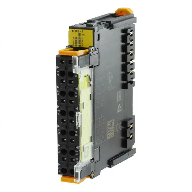
GRT1-OD8
Transistor output
(NPN type, sinking)
GRT1-OD8-1
Transistor output
(PNP type, sourcing)
Number of output points
8 outputs
Power terminals
Rated voltage
Rated output current
Residual voltage
Leakage cuurent
ON delay / Off delay
Mechanical life expectancy
Electrical life expectancy
4 x V (24 V)
4 x G (0 V)
24 VDC (20.4 to 26.4 VDC)
500 mA max./point
1.2 VDC max. (at 500 mA)
0.1 mA max.
0.5 / 1.5 ms max.
-
GRT1-OD4
0
1
V
GRT1-OD8G-1
GRT1-ROS2
Transistor output
Relay output
(PNP type, sourcing),
(normally open)
with short-circuit protection
2 outputs (with 2 terminals per connection)
n.a.
250 VAC / 24 VDC
2 A (min. 1 mA @ 5 VDC)
15 ms max.
20,000,000 times min.
100,000 times min.
GRT1-OD4-1
0
1
V
NC
NC
NC
NC
G
2
3
V
NC
GRT1-OD4G-1 (PNP)
0
1
V
V
G
G
G
2
3
2
3
V
NC
NC
V
V
NC
G
G
G
G
Solenoid,
valve, etc.
3-wire
actuator
GRT1-PC8-1
3-wire
actuator
Solenoid,
valve, etc.
GRT1-OD8 (NPN)
Solenoid,
valve, etc.
3-wire
actuator
GRT1-OD4G-3 (PNP)
GRT1-OD8
G
G
0
1
G
G
V
V
V
V
0
1
G
G
2
3
G
G
V
V
Solenoid,
valve, etc.
24 VDC
G
G
4
5
V
V
V
V
2
3
G
G
6
7
G
G
Solenoid,
valve, etc.
GRT1-PC8
3-wire
actuator
3-wire
actucator
3-wire
actuator
3-wire
actuator
GRT1-OD8(G)-1 (PNP)
GRT1-ROS2
GRT1-OD8-1
V
V
0
1
0
0
V
V
2
3
C0
C0
G
G
G
G
NC
NC
V
V
4
5
1
1
V
V
6
7
C1
C1
G
G
G
G
NC
NC
Solenoid,
valve, etc.
134
+
3-wire
actuator
AC power supply
(or DC power supply)
Load
AC power supply
(or DC power supply)
Load
�s08b_smartslice.fm Page 135 Monday, December 19, 2011 3:45 PM
SmartSlice I/O
System Configuration
Analog I/O Units
Model name
Signal type
GRT1-AD2
Analog Input: 0-20mA,
4-20mA,
±10V, 0-10V, 0-5V, 1-5V
2 inputs
1/6000 full scale
2ms / 2points
GRT1-DA2V
GRT1-DA2C
Analog Output:
Analog Output:
±10V, 0-10V, 0-5V, 1-5V 0-20mA, 4-20mA,
Model name
Signal type
GRT1-TS2P
Temperature input,
Pt100, (2-wire, 3-wire)
GRT1-TS2PK
GRT1-TS2T
Temperature input,
Thermocouple,
Pt1000, (2-wire, 3-wire) R, S, K, J, T, E, B, N, L,
U, W, or PL2
Number of points
Indication range
2 inputs
-200 to +200 °C /
-200 to +850 °C
±0.3% of PV or ±0.8 °C* (whichever is larger)
±1 digit max.
* (or ±0.5 °C for -200 °C to +200 °C input range)
Accuracy
0.1 °C, 16-bit signed integer, or
0.01 °C, 32-bit signed double integer
250 ms / 2 points
Conversion time
GRT1-AD2
GRT1-DA2V
0+
1+
GRT1-DA2C
NC
NC
NC
NC
NC
NC
NC
NC
NC
NC
I0 +
I1 +
0-
1-
NC
NC
IN1
0-
1-
AG
AG
Sh0
Sh1
Sh0
Sh1
Short for IN1
current input
0-
1-
NC
NC
GRT1-TS2P/PK (3-wire)
1A
0A
1A
0B
1B
0B
1B
0B
1B
0B
1B
SHT SHT
0A
1A
SHT SHT
0B
1B
SHT SHT
0B
1B
NC
NC
NC
NC
GRT1-TS2T
Thermocouple input
NC
NC
0−
1−
0+
1+
NC
NC
NC
NC
Cold Junction Sensor
(do not remove)
Vision Sensor
SHT SHT
0A
1A
OUT
1
Dimensions
0A
OUT
0
OUT
1
Wiring
GRT1-TS2P/PK (2-wire)
V0 + V1 +
OUT
0
Multi-function Compact Inverter
NC
Specifications
NC
AC Servomotors / Servo Drives
NC
System
Configuration
NC
IN0
Short for IN0
current input
Depends on thremocouple type
±2°C ±1 digit max.
Mounting restrictions
apply. See Operation
Manual W455
Automation Software
Resolution
2 outputs
Machine Automation Controller
Number of points
Resolution
Conversion time
Remote I/O Terminals
Ordering Information
135
�s08b_smartslice.fm Page 136 Monday, December 19, 2011 3:45 PM
SmartSlice I/O
Power Feed and Distribution Units
GRT1-PD2
24 VDC
GRT1-PD2G
NC
NC
NC
NC
NC
NC
V
V
G
NC
136
RESET NC
V
V
V(R)
NC
V
V
NC
NC
G
G
V
V
V
V
G
G
G
V
V
NC
NC
NC
G
G
GRT1-PD8-1
24 VDC
GRT1-PD8
24 VDC
GRT1-PC8
24 VDC
GRT1-PC8-1
G
G
V
V
G
G
V
V
V
V
V
V
G
G
G
G
G
G
G
G
V
V
G
G
V
V
V
V
V
V
G
G
G
G
G
G
�44
Automation Software
36.8
2.5
58
16.2
30.2
42.8
54.1
80
Machine Automation Controller
13.8
27.6
44
GRT1-ECT
Specifications
Dimensions
Multi-function Compact Inverter
Wiring
Vision Sensor
Remote I/O Terminals
Ordering Information
137
AC Servomotors / Servo Drives
System
Configuration
GRT1-END
GRT1-END-M
GRT1-TBR
Communication Units
I/O-units
61.2
69.7
1.5
System Configuration
13.1
s08b_smartslice.fm Page 137 Monday, December 19, 2011 3:45 PM
SmartSlice I/O
Dimensions
End units
�