P15E-EN-03B+SmartSlice+Datasheet.fm Seite 1 Dienstag, 30. August 2011 12:34 12
SmartSlice
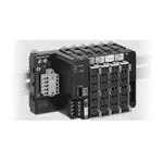
The smartest modular I/O system
OMRON's SmartSlice I/O system is compact, intelligent and
easy. When used with OMRON's CS1/CJ1 DeviceNet or
CompoNet master units, no configuration tool is required.
By using built-in functions such as pre-scaling, totalising,
differentiation and alarming in analog I/O units, PLC programming can be minimised. Preventive maintenance data
collected by all I/O units can be accessed using CX-Integrator or NS-series Smart Active Parts.
• Most compact in the market (84 mm high)
• Easy set-up, backup and restore functions
• Diagnostics and preventive maintenance data at I/O level
• Detachable terminal blocks allow hot-swapping without
re-wiring
• 3-wire I/O connection with 'push-in' technology, no screwdriver required
System Configuration
NJ series Controller,
CS/CJ PLC series or
Trajexia Motion Controller
CX-One for setup,
monitoring and operation
of all OMRON Devices
PLC
Slave
Communication Unit
GRT1-TBR Right Turnback Unit
GCN2-100 Turnback Cable (1 m)
Max. 2 per station.
I/O Units
GRT1-END End Unit
GRT1-TBL Left Turnback Unit
Up to 64 I/O Units can be connected to a Communication Unit.
SmartSlice
1
�P15E-EN-03B+SmartSlice+Datasheet.fm Seite 2 Dienstag, 30. August 2011 12:34 12
Specifications
General Specifications
Common SmartSlice Specifications
Unit power supply voltage
24 VDC (20.4 to 26.4 VDC)
I/O power supply voltage
24 VDC (20.4 to 26.4 VDC)
I/O connection
Screwless push-in technology
Noise immunity
Conforms to IEC61000-4-4, 2.0 kV (power supply line)
Vibration resistance
10 to 60 Hz: 0.7 mm double amplitude 60 to 150 Hz: 50 m/s2
Shock resistance
150 m/s2, 3 times in each direction
Dielectric strength
500 VAC (between isolated circuits)
Insulation resistance
20 M min. (between isolated circuits)
Ambient operating temperature
-10 to 55°C (with no icing or condensation)
Ambient operating humidity
25% to 85%
Operating environment
No corrosive gases
Ambient storage temperature
-25 to 65°C (with no icing or condensation)
Mounting
35 mm DIN rail
Communication Units
Model name
Network Specification
GRT1-PNT
PROFINET-IO
GRT1-PRT
PROFIBUS-DPV1
Network connector
2 x RJ45, built-in
switch with support
for MRP
redundancy.
9-pin D-Sub
Network interface power supply
Number of I/O points
Number of connectable Units
I/O power supply
Status flags
Parameter backup and restore
2
GRT1-DRT
DeviceNet
GRT1-CRT
CompoNet
Open-style
4-pin CompoNet
DeviceNet
connector,
dual screwless
push-in dual
connections.
Internal
External,
Internal
11 to 25 VDC, 22 mA
1,024 inputs and outputs max. (128 bytes each)
32 bytes input +
32 bytes output
max.
64 SmartSlice I/O Units max.
24 VDC, 4 A max.
1 word for Communications Unit status flags
up to 2 KB of data per I/O Unit.
GRT1-ML2
GRT1-ECT
MECHATROLINK-II EtherCAT for
for Trajexia
Trajexia and
Sysmac (NJ)
2 x ML-II
2 x RJ45
1,024 inputs and
outputs max.
(128 bytes total)
External 24 VDC
(+10% - 15%)
1,024 inputs and
outputs max.
(128 bytes total)
Control System
�P15E-EN-03B+SmartSlice+Datasheet.fm Seite 3 Dienstag, 30. August 2011 12:34 12
Digital Input Units
Model name
Signal type
GRT1-ID4
GRT1-ID4-1
DC input (for sinking out- DC input (for sourcing
puts, NPN type)
outputs, PNP type)
4 inputs
4 x V (24 V) + 4 x G (0 V)
15 VDC min.
6 mA max./point (at 24 VDC)
5 VDC max.
1 mA max.
1.5 ms max.
Number of input points
Power terminals
ON voltage
ON current
OFF voltage
OFF current
ON delay / OFF delay
Model name
Signal type
Number of input points
Power terminals
Input voltage
GRT1-IA4-1
AC input, 110 V
4 inputs
None
100 to 120 VAC
-15% to +10%, 50/60 Hz
70 VAC min.
4 mA min.
20 VAC max.
2 mA max.
10 ms max./55 ms max.
ON voltage
ON current
OFF voltage
OFF current
ON delay / OFF delay
V
2-wire sensor
(such as a limit switch)
4 x V (24 V)
4 mA max./point (at 24 VDC)
200 to 240 VAC
-15% to +10%, 50/60 Hz
120 VAC min.
10 ms max./40 ms max.
GRT1-ID4 -1 (PNP)
0
–
GRT1-ID8-1
DC input (for sourcing
outputs, PNP type)
GRT1-IA4-2
AC input, 230 V
GRT1-ID4 (NPN)
+
GRT1-ID8
DC input (for sinking outputs, NPN type)
8 inputs
4 x G (0 V)
1
V
Signal
–
24 V
+
0V
2-wire sensor
(such as a limit switch)
3-wire sensor
with NPN output
(photoelectric or
proximity sensor)
0
1
V
V
G
G
2
3
Signal
24 V
0V
G
G
2
3
V
V
V
V
G
G
G
G
3-wire sensor with NPN output
(photoelectric or proximity sensor)
GRT1-IA4-1/GRT1-IA4-2
0A
1A
0A
1A
0A
1A
0B
1B
0B
1B
0B
1B
0B
1B
0B
1B
0B
1B
2A
3A
2A
3A
2A
3A
2B
3B
2B
3B
2B
3B
2B
3B
2B
3B
2B
3B
Note: Common signal for four inputs.
V
0
1
G
Signal
24 V
GRT1-PC8-1
3-wire sensor
0V
GRT1-ID8
Signal
Signal
V
3-wire sensor
24 V
GRT1-ID8-1 (PNP)
3-wire sensor
24 V
Signal
24 V
GRT1-PD8
0V
3-wire sensor
0V
GRT1-ID8 (NPN)
0V
Note: No common signal for inputs.
GRT1-ID8-1
G
0
1
V
V
2
3
V
V
V
V
G
G
G
G
G
G
2
3
V
V
4
5
G
G
4
5
V
V
6
7
V
V
V
V
G
G
G
G
G
G
6
7
3-wire sensor
Signal
24 V
–
+
2-wire switch
0V
24 V
2-wire switch
0V
–
SmartSlice
+
External
24-V I/O
power
supply
Signal
−
+
3-wire sensor
3
�P15E-EN-03B+SmartSlice+Datasheet.fm Seite 4 Dienstag, 30. August 2011 12:34 12
Digital Output Units
Model name
Signal type
Number of output points
Power terminals
Rated voltage
GRT1-OD4
GRT1-OD4-1
Transistor output
Transistor output
(NPN type, sinking)
(PNP type, sourcing)
4 outputs
4 x V (24 V)
4 x G (0 V)
24 VDC (20.4 to 26.4 VDC)
Rated output current
500 mA max./point
Residual voltage
Leakage cuurent
ON delay / Off delay
1.2 VDC max. (at 500 mA)
0.1 mA max.
0.5 / 1.5 ms max.
Model name
Signal type
GRT1-OD8
Transistor output
(NPN type, sinking)
Number of output points
8 outputs
Power terminals
Rated voltage
Rated output current
Residual voltage
Leakage cuurent
ON delay / Off delay
Mechanical life expectancy
Electrical life expectancy
4 x V (24 V)
4 x G (0 V)
24 VDC (20.4 to 26.4 VDC)
500 mA max./point
1.2 VDC max. (at 500 mA)
0.1 mA max.
0.5 / 1.5 ms max.
-
GRT1-OD4
0
1
V
GRT1-OD8-1
Transistor output
(PNP type, sourcing)
GRT1-OD4G-1
GRT1-OD4G-3
Transistor output
(PNP type, sourcing), with short-circuit protection
4 x V (24 V) + 4 x G (0 V)
24 V I/O power supply
via the front terminal of
the unit.
from 4 x 2.0 A at 30 °C
to 4 x 1.0 A at 55 °C
1.2 VDC max. (at 2 A)
GRT1-OD8G-1
GRT1-ROS2
Transistor output
Relay output
(PNP type, sourcing),
(normally open)
with short-circuit protection
2 outputs (with 2 terminals per connection)
n.a.
250 VAC / 24 VDC
2 A (min. 1 mA @ 5 VDC)
15 ms max.
20,000,000 times min.
100,000 times min.
GRT1-OD4-1
0
1
V
NC
NC
NC
NC
G
2
3
V
NC
GRT1-OD4G-1 (PNP)
0
1
V
V
G
G
G
2
3
2
3
V
NC
NC
V
V
NC
G
G
G
G
Solenoid,
valve, etc.
3-wire
actuator
GRT1-PC8-1
3-wire
actuator
Solenoid,
valve, etc.
GRT1-OD8 (NPN)
Solenoid,
valve, etc.
3-wire
actuator
GRT1-OD4G-3 (PNP)
GRT1-OD8
G
G
0
1
V
V
V
V
G
G
0
1
G
G
V
V
Solenoid,
valve, etc.
24 VDC
G
G
2
3
G
G
4
5
V
V
V
V
2
3
G
G
6
7
G
G
Solenoid,
valve, etc.
4
+
3-wire
actucator
3-wire
actuator
Control System
�P15E-EN-03B+SmartSlice+Datasheet.fm Seite 5 Dienstag, 30. August 2011 12:34 12
GRT1-PC8
3-wire
actuator
GRT1-OD8(G)-1 (PNP)
3-wire
actuator
GRT1-ROS2
GRT1-OD8-1
V
V
0
1
0
0
V
V
2
3
C0
C0
G
G
G
G
NC
NC
V
V
4
5
1
1
V
V
6
7
C1
C1
G
G
G
G
NC
NC
Solenoid,
valve, etc.
AC power supply
(or DC power supply)
Load
AC power supply
(or DC power supply)
Load
3-wire
actuator
Pulse I/O Units
Model name
Counter input
GRT1-CT1
A/B incremental
encoder,
or pulse/direction,
or pulse up/down
24 VDC, NPN type
Counter signal type
Max. frequency
Counter range
Comparison values
Control Input
Control Input functions
GRT1-CT1-1
A/B incremental
encoder,
or pulse/direction,
or pulse up/down
24 VDC, PNP type
GRT1-CP1-L
A/B/Z incremental
encoder,
or pulse/direction/reset
24 VDC, PNP type, or
RS422 Line driver levels
100 kHz
60 kHz
32 bit double signed integer
1 range (2 comparison values)
2 independent ranges
IN0, DC input (NPN type) IN0, DC input (PNP type)
Capture, Preset, Reset
Capture, Preset, Reset,
Z enable
OUT0, Transistor Output OUT0, Transistor Output OUT0, OUT1, Transistor
(NPN, sinking)
(PNP, sourcing)
Output (PNP, sourcing)
Range comparison, manual override
On-the-fly reconfiguration, Frequency measurement
Control Outputs
Control Output functions
Additional functions
Note: Pulse I/O Units are not supported by GRT1-ML2 and GRT1-ECT.
GRT1-CT1(-1)
GRT1-CP1-L
GRT1-CT1 (NPN)
24-V rotary encoder
(all DIP switch pins ON)
GRT1-CT1-1 (PNP)
Line driver rotary encoder
(all DIP switch pins OFF)
A
OUT
A
OUT
A
N.C.
A+
A–
B
V
B
N.C.
B
N.C.
B+
B–
Z/IN
N.C.
Z/IN
G
Z
N.C.
Z+
Z–
N.C.
N.C.
N.C.
N.C.
IN
OUT0
IN
OUT0
V
V
V
V
V
OUT1
V
OUT1
G
G
G
G
G
G
G
G
SmartSlice
5
�P15E-EN-03B+SmartSlice+Datasheet.fm Seite 6 Dienstag, 30. August 2011 12:34 12
Analog I/O Units
Model name
Signal type
GRT1-AD2
Analog Input: 0-20mA,
4-20mA,
±10V, 0-10V, 0-5V, 1-5V
2 inputs
1/6000 full scale
2ms / 2points
GRT1-DA2V
GRT1-DA2C
Analog Output:
Analog Output:
±10V, 0-10V, 0-5V, 1-5V 0-20mA, 4-20mA,
Model name
Signal type
GRT1-TS2P
Temperature input,
Pt100, (2-wire, 3-wire)
GRT1-TS2PK
GRT1-TS2T
Temperature input,
Thermocouple,
Pt1000, (2-wire, 3-wire) R, S, K, J, T, E, B, N, L,
U, W, or PL2
Number of points
Indication range
2 inputs
-200 to +200 °C /
-200 to +850 °C
±0.3% of PV or ±0.8 °C* (whichever is larger)
±1 digit max.
* (or ±0.5 °C for -200 °C to +200 °C input range)
Number of points
Resolution
Conversion time
Accuracy
Resolution
GRT1-AD2
GRT1-DA2V
NC
NC
0+
1+
GRT1-DA2C
NC
NC
NC
NC
NC
NC
NC
NC
NC
NC
NC
NC
I0 +
I1 +
IN1
IN0
0-
1-
AG
AG
Sh0
Sh0
V0 + V1 +
OUT
0
Sh1
Sh1
GRT1-TS2P/PK (2-wire)
6
Depends on thremocouple type
±2°C ±1 digit max.
Mounting restrictions
apply. See Operation
Manual W455
0.1 °C, 16-bit signed integer, or
0.01 °C, 32-bit signed double integer
250 ms / 2 points
Conversion time
Short for IN0
current input
2 outputs
Short for IN1
current input
0-
1-
NC
NC
GRT1-TS2P/PK (3-wire)
0A
1A
0A
1A
0B
1B
0B
1B
0B
1B
0B
1B
SHT SHT
0A
1A
SHT SHT
0A
1A
SHT SHT
0B
1B
SHT SHT
0B
1B
NC
NC
NC
NC
OUT
0
OUT
1
OUT
1
0-
1-
NC
NC
GRT1-TS2T
Thermocouple input
NC
NC
0−
1−
0+
1+
NC
NC
NC
NC
Cold Junction Sensor
(do not remove)
Control System
�P15E-EN-03B+SmartSlice+Datasheet.fm Seite 7 Dienstag, 30. August 2011 12:34 12
Power Feed and Distribution Units
GRT1-PD2
24 VDC
GRT1-PD2G
NC
NC
NC
NC
V(R)
NC
NC
RESET NC
24 VDC
V
V
NC
V
V
NC
NC
G
G
V
V
V
V
V
V
G
G
V
V
G
G
G
G
NC
NC
NC
NC
GRT1-PD8-1
24 VDC
GRT1-PD8
GRT1-PC8
24 VDC
GRT1-PC8-1
G
G
V
V
G
G
V
V
V
V
V
V
G
G
G
G
G
G
G
G
V
V
G
G
V
V
V
V
V
V
G
G
G
G
G
G
SmartSlice
7
�P15E-EN-03B+SmartSlice+Datasheet.fm Seite 8 Dienstag, 30. August 2011 12:34 12
Dimensions
I/O-units
Communication Units
GRT1-CRT
GRT1-DRT
GRT1-ECT
GRT1-ML2
GRT1-PNT
GRT1-PRT
GRT1-TBL
End units
GRT1-END
GRT1-END-M
GRT1-TBR
8
Control System
�P15E-EN-03B+SmartSlice+Datasheet.fm Seite 9 Dienstag, 30. August 2011 12:34 12
Ordering Information
Communication Units
Function
DeviceNet interface unit
CompoNet interface unit
PROFIBUS-DP interface unit
PROFINET-IO interface unit
MECHATROLINK-II interface unit
EtherCAT interface unit
End plate
End plate with memory function
Specification
For up to 64 I/O units
For up to 64 I/O units (limited to 32 byte in + 32 byte out)
For up to 64 I/O units
For up to 64 I/O units
For up to 64 I/O units (slave to Trajexia motion controller)
For up to 64 I/O units (slave to Trajexia and Sysmac controllers)
One unit required per bus interface
Supports toolless replacement of PROFINET-IO interface unit
84x58x70
84x58x70
84x58x70
84x58x70
84x58x70
84x58x70
84x20x58
84x20x58
Model code
GRT1-DRT
GRT1-CRT
GRT1-PRT
GRT1-PNT
GRT1-ML2
GRT1-ECT
GRT1-END
GRT1-END-M
84x15x74
84x15x74
84x15x74
84x15x74
84x15x74
84x15x74
84x15x74
84x15x74
84x15x74
84x15x74
84x15x74
84x15x74
84x15x74
84x15x74
84x15x74
84x15x74
84x15x74
Model code
GRT1-ID4
GRT1-ID4-1
GRT1-ID8
GRT1-ID8-1
GRT1-IA4-1
GRT1-IA4-2
GRT1-OD4
GRT1-OD4-1
GRT1-OD4G-1
GRT1-OD4G-3
GRT1-OD8
GRT1-OD8-1
GRT1-OD8G-1
GRT1-ROS2
GRT1-CT1
GRT1-CT1-1
GRT1-CP1-L
84x15x74
84x15x74
84x15x74
84x15x74
84x15x74
84x15x74
GRT1-AD2
GRT1-DA2V
GRT1-DA2C
GRT1-TS2P
GRT1-TS2PK
GRT1-TS2T
84x15x74
84x15x74
84x15x74
84x15x74
84x15x74
84x15x74
84x20x58
84x58x70
1m
Model code
GRT1-PD2
GRT1-PD2G
GRT1-PD8
GRT1-PD8-1
GRT1-PC8
GRT1-PC8-1
GRT1-TBR
GRT1-TBL
GCN2-100
I/O units
Function
4 NPN inputs
4 PNP inputs
8 NPN inputs
8 PNP inputs
4 AC inputs
4 AC inputs
4 NPN outputs
4 PNP outputs
4 PNP outputs with short-circuit protection
4 PNP outputs with short-circuit protection
8 NPN outputs
8 PNP outputs
8 PNP outputs with short-circuit protection
2 relay outputs
60 kHz Counter unit, NPN
60 kHz Counter unit, PNP
100 kHz Counter / Positioner unit
2 analog inputs, current/voltage
2 analog outputs, voltage
2 analog outputs, current
2 Pt100 inputs
2 Pt1000 inputs
2 Thermocouple inputs
Specification
24 VDC, 6 mA, 3-wire connection
24 VDC, 6 mA, 3-wire connection
24 VDC, 4 mA, 1-wire connection + 4xG
24 VDC, 4 mA, 1-wire connection + 4xV
110 VAC, 2-wire connection
230 VAC, 2-wire connection
24 VDC, 500 mA, 2-wire connection
24 VDC, 500 mA, 2-wire connection
24 VDC, 500 mA, 3-wire connection
24 VDC, 2 A, 2-wire connection
24 VDC, 500 mA, 1-wire connection + 4xV
24 VDC, 500 mA, 1-wire connection + 4xG
24 VDC, 500 mA, 1-wire connection + 4xG
240 VAC, 2A, normally-open contacts
A+B encoder inputs + 1 Z/control input + 1 output (NPN-type)
A+B encoder inputs + 1 Z/control input + 1 output (PNP-type)
A+B+Z encoder inputs (line driver or 24 V selectable) +
1 control input + 2 outputs (PNP-type)
±10 V, 0-10 V, 0-5 V, 1-5 V, 0-20 mA, 4-20 mA
±10 V, 0-10 V, 0-5 V, 1-5 V
0-20 mA, 4-20 mA
Pt100, 2-wire or 3-wire connection
Pt1000, 2-wire or 3-wire connection
Types B, E, J, K, N, R, S, T, U, W, PL2, with cold junction compensation
Other units
Function
I/O power feed unit, separates power supply between groups of I/O units
I/O power feed unit with electronic overload protection, separates power supply between groups of I/O units
I/O power feed and distribution unit, separates power supply between groups of I/O units, 8xV + 4xG
I/O power feed and distribution unit, separates power supply between groups of I/O units, 4xV + 8xG
I/O power connection unit, 8xV + 4xG
I/O power connection unit, 4xV + 8xG
Turnback Unit, right-hand side
Turnback Unit, left-hand side
Turnback cable, one meter
Accessories
Function
Replacement front connectors, pack of 5 pcs.
PROFIBUS-DP connector, 9-pin D-sub
PROFIBUS-DP connector, 9-pin D-sub, with bus termination
CompoNet screw terminal connector (order per 10 pcs)
CompoNet branch line connector (order per 10 pcs)
CompoNet Y-connector (order per 10 pcs)
SmartSlice
Model code
GRT1-BT1-5
PROFIBUS Connector
839550
PROFIBUS Term. Conn.
846086
DCN4-TB4
DCN4-BR4
DCN4-MD4
9
�P15E-EN-03B+SmartSlice+Datasheet.fm Seite 10 Dienstag, 30. August 2011 12:34 12
Master Units
Function
PROFINET-IO Controller for CJ1-series PLCs
PROFIBUS-DP Master Unit for CS1-series PLCs
PROFIBUS-DP Master Unit for CJ1-series PLCs
DeviceNet Master Unit for CS1-series PLCs
DeviceNet Master Unit for CJ1-series PLCs
CompoNet Master Unit for CS1-series PLCs
CompoNet Master Unit for CJ1-series PLCs
MECHATROLINK-II Master Unit for Trajexia (4 stations max.)
MECHATROLINK-II Master Unit for Trajexia (16 stations max.)
EtherCAT Master Unit for Trajexia
HMI with PLC and DeviceNet Master
HMI with PLC and PROFIBUS-DP Master
Model code
CJ1W-PNT21
CS1W-PRM21
CJ1W-PRM21
CS1W-DRM21-V1
CJ1W-DRM21
CS1W-CRM21
CJ1W-CRM21
TJ1-ML04
TJ1-ML16
TJ2-ECT@@
NSJxx-T@@@@-G5D
NSJxx-T@@@@-G5P
Software
Function
CX-One, Omron's integrated software for programming and configuration of all control system components,
including PLCs, remote I/O, HMI, servo drives, inverters, temperature controllers and advanced sensors.
Cat. No. P15E-EN-03B
Model code
CX-ONE-AL@@ C-E
@@ = number of licenses
(01, 03, 10)
In the interest of product improvement, specifications are subject to change without notice.
OMRON EUROPE B.V.
Wegalaan 67-69,
NL-2132 JD, Hoofddorp,
The Netherlands
Phone: +31 23 568 13 00
Fax: +31 23 568 13 88
www.industrial.omron.eu
10
Control System
�


 工商网监
湘ICP备2023018690号
工商网监
湘ICP备2023018690号
