Analog Input Modules
GT1-AD
Analog Input Module Compatible with
MULTIPLE I/O TERMINAL
Input block incorporates connectors that can be
easily mounted or dismounted.
8 inputs
High resolution of 1/6,000
High conversion speed of 8 ms/8 points or 4 ms/4
points.
Dimensions of connector model:
110 × 60 × 65 (W × H × D)
Dimensions of terminal block model:
80 × 80 × 65 (W × H × D)
DIN track mounting.
Ordering Information
I/O classification
Analog input
Note:
I/O points
Terminal
8
Molex connector
4
Terminal block
Power supply
voltage
24 VDC
I/O specification
4 to 20 mA, 0 to 20 mA,
0 to 5 V, 1 to 5 V, 0 to
10 V, --10 to 10 V
Model
GT1-AD08MX
GT1-AD04
A connector cable, GCN1--004, is included with each module.
Specifications
Input
Item
Voltage input
Current input
Input points
8
Input type
0 to 5 V, 1 to 5 V, 0 to 10 V, --10 to 10 V
0 to 20 mA, 4 to 20 mA
Max. signal input
±15 V
±30 mA
Input impedance
1 MW min.
Approx. 250 W
Resolution
1/6,000 (FS)
Overall accuracy
25°C
±0.3% FS
±0.4% FS
--10°C to 55°C
±0.6% FS
±0.8% FS
Conversion speed
8 ms/8 points, 4 ms/4 points
Conversion output data
Binary data
--10- to 10-V range: F448 to 0BB8 full scale
Other signal ranges: 0000 to 1770 full scale
Insulation method
Transistor or photocoupler insulation between inputs and power lines.
54
�GT1-AD
GT1-AD
Characteristics
I/O power supply voltage
20.4 to 26.4 VDC (24 VDC +10%/--15%)
Current consumption
I/O module interface
Internal circuitry power supply
50 mA max.
100 mA max.
Noise immunity
±1,500 V (p-p) with a pulse width of 0.1 to 1 ms
Vibration resistance
10 to 150 Hz, 1.0-mm double amplitude or 70 m/s2
Shock resistance
200 m/S2
Dielectric strength
500 VAC
Mounting method
35-mm DIN track mounting
Mounting strength
No damage when 100 N pull load was applied in all directions (10 N min. in the DIN track
direction)
Terminal strength
No damage when 100 N pull load was applied
Ambient temperature
Operating:
Storage:
--10°C to 55°C (with no icing or condensation)
--25°C to 65°C (with no icing or condensation)
Ambient humidity
Operating:
25% to 85%
Connector
Type
Molex connector
Note:
Model
Remarks
IDC (Use Press-fit tool.)
Housing
GCN1--MX25--B*
(25 piece bag from
OMRON) 22 AWG
Solderless terminal
Housing
50--57--9403
Chain terminal
16--02--0069
24 to 30 AWG
16--02--0086
22 to 24 AWG
Loose terminal
16--02--0096
24 to 30 AWG
Press-fit tool
11--01--0209
(See Note.)
Contact your OMRON representatives for the above connectors.
*Stocked by OMRON.
Nomenclature
GT1-AD08MX
TS indicator (status indicator of I/O Module interface)
Indicates the status of the I/O Module Interface.
PWR indicator (internal power supply indicator)
The green indicator is lit when internal circuitry power supply is provided.
U.ERR indicator (module error indicator)
The red indicator is lit if the Module malfunctions or no internal
circuitry power supply is provided.
Connectors for I/O module interface
Connects to the Communications Units or other I/O Modules.
+24VDC
·
·
Connect the Communications Module to connector 1.
·
Be sure to connect the end connector to connector 2 of
the last I/O Module.
-24VDC
Internal power
supply terminals
Supply 24 VDC +10%/--15% to these
terminals for the operation of the
Module.
Specification
Setting
Switch
Voltage input COM Current input
Analog input connectors 0 to 7
These connectors are for analog input use.
Each input connector has three pins (i.e., a pin for
voltage input, COM, and current input from left to
right)
When connecting I/O Modules to the GT1-AD,
connector 2 of the GT1-AD must be connected to
connector 1 of the first I/O Module and connector 2 of
the first I/O Module must be connected to connector 1
of the next I/O Module. Connect all the I/O Modules in
the same way.
TS Indicator (Status Indicator of I/O Module Interface)
Green indicator lit
The Module is normal.
Red indicator lit
The I/O Module interface has an error.
OFF
No power is supplied to the Module or
the Module is being initialized.
55
�GT1-AD
GT1-AD
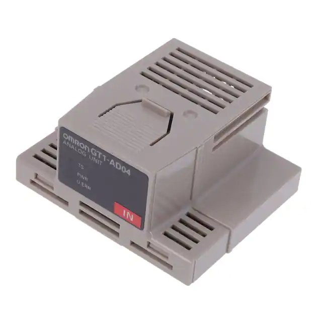
GT1-AD04
TS indicator
Indicates the communications status of the I/O Module Interface.
PWR indicator
The indicator is lit green when internal circuitry power supply is provided.
The indicator is not lit when internal circuitry power is not supplied.
U.ERR indicator
The indicator is lit red if the Module malfunctions or no internal
circuitry power supply is provided. The indicator is not lit when the
Module is normal.
Connector 1 for I/O Module interface
(connects to Communications Module)
Connector 2 for I/O Module interface (connects to end node)
Specification setting switch
Located on left side of the
connecting section.
Cassette
Lightly push the upper part, then pull out to disconnect.
Terminal block
DIN Track connection hook
TS Indicator
(Communications Status Indicator of I/O Module Interface)
Green indicator lit
The Module is normal.
Red indicator lit
The I/O Module interface has an error.
Not lit
No power is supplied to the Module or
the Module is being initialized.
Operation
Internal Circuit Configuration
GT1-AD08MX
Photocoupler
I/O Module interface
Photocoupler
I/O Module interface
I/O Module interface
Input circuit
+24 VDC
Internal circuitry
power supply
Insulated DC-DC
converter
Internal circuit
--24 VDC
Eight circuits
GT1-AD04
I/O Module interface
Photocoupler
Photocoupler
I/O Module interface
Input circuit
+24 VDC
Internal circuitry
power supply
Insulated DC-DC
converter
Internal circuit
--24 VDC
Four circuits
56
I/O Module interface
�GT1-AD
GT1-AD
Dimensions
Note:
All units are in millimeters unless otherwise indicated.
GT1-AD08MX
GT1-AD04
Installation
Wiring
Be sure to connect Molex-made connectors for analog input wires and connect the wires as shown below.
Internal Circuitry Power Supply
Voltage Input
Current Input
24 VDC
57
�GT1-AD
GT1-AD
Precautions
Refer to the DeviceNet Operation Manual (W267) before using the
Module.
Wiring
· To prevent
inductive noise, do not wire power lines or
high-tension lines along with or near the cables. Other
noise-prevention techniques, such as using shielding or
separate conduit/ducting, are also effective.
·
Install the Module as far as possible from equipment that
generates strong high-frequency signals (such as high-frequency welders) and equipment that generates surges. Such
equipment can cause the Module to malfunction.
·
Install surge absorbers or noise filters on nearby equipment that
generates noise, particularly equipment that has inductive
components such as motors, transformers, solenoids, or
magnetic coils.
·
When using a noise filter in the power supply, check the voltage
and current and install the noise filter as close as possible to the
Module.
NOTE: DIMENSIONS SHOWN ARE IN MILLIMETERS. To convert millimeters to inches divide by 25.4.
R
OMRON ELECTRONICS, INC.
OMRON CANADA, INC.
1-800-55-OMRON
416-286-6465
One East Commerce Drive
Schaumburg, IL 60173
Cat. No. PP10FAX1A
58
6/00
885 Milner Avenue
Scarborough, Ontario M1B 5V8
Specifications subject to change without notice.
Printed in U.S.A.
�Mouser Electronics
Authorized Distributor
Click to View Pricing, Inventory, Delivery & Lifecycle Information:
Omron:
GT1-AD04 GT1-AD04CST GT1-AD08MX
�
很抱歉,暂时无法提供与“GT1-AD04CST”相匹配的价格&库存,您可以联系我们找货
免费人工找货