New Product News
22.5-mm-width Timers
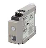
H3DKZ
Range of DIN Track-mounted, Standard
22.5-mm-width Timers
• A wide AC/DC power supply range (24 to 240 VAC/DC).*
• ON-delay Timers and Twin Timers include models with 12-VDC
power supply.*
• G-type Models (H3DKZ-G) now include model with 240 to 440VAC power supply.
• EN 61812-1 compliance, CE Marking, and CCC certification.
• Finger-safe terminal block.
*.Except for the H3DKZ-H.
Model Number Structure
■ The Entire H3DKZ Series
H3DKZ Series
H3DKZ-A
ON-delay Timers
H3DKZ-F
Twin Timers
Page 2
■ ON-delay Timers
H3DKZ-A1/A2
● Operating Mode
A: ON Delay
H3DKZ-G
Star-delta Timers
Page 7
● Operating Modes
Flicker-OFF Start/
Flicker-ON Start
H3DKZ-H Power
OFF-delay Timers
Page 11
● Operating Modes
Star-delta Timer
Page 16
● Operating Modes
Power OFF-delay
Timer
■ Model Number Legend (Not all models that can be represented with the model number legend can necessarily be produced.)
H3DKZ-@@@@
1 2 3 4
1. Type
Symbol
2. Control Output
Meaning
3. Supply Voltage
Symbol
Meaning
Symbol
A
ON-delay Timer
1
SPDT
Blank
F
Twin Timer
2
DPDT
A
G
Star-delta Timer
H
Power OFF-delay Timer
* A-type models only.
Meaning
24 to 240 VAC/DC
12 VDC
B
24 to 48 VAC/DC
C
100 to 120 VAC
D
200 to 240 VAC
E
240 to 440 VAC *
4. Time Ranges (H-type
Models Only)
Symbol
L
Meaning
1 to 12 s or 10 to 120 s
* G-type models only.
1
�New Product News
ON-delay Timer
H3DKZ-A
• A wide time setting range of 0.10 s to 1200 h.
• Single mode (On-delay) Timer.
• A wide AC/DC power supply range (24 to 240 VAC/DC).
• Models with 12-VDC power supply available.
Ordering Information
■ List of Models
Supply voltage
Control output
Model
SPDT (time-limit output)
24 to 240 VAC/DC
12 VDC
H3DKZ-A1
DPDT (time-limit output)
H3DKZ-A2
SPDT (time-limit output)
H3DKZ-A1A
DPDT (time-limit output)
H3DKZ-A2A
■ Accessories (Order Separately)
Item
Specification
Model
50 cm (l) x 7.3 mm (t)
Mounting Track
PFP-50N
1 m (l) x 7.3 mm (t)
PFP-100N
1 m (l) x 16 mm (t)
PFP-100N2
End Plate
---
PFP-M
Spacer
---
PFP-S
■ Model Structure
Model
Operating modes
H3DKZ-A2
Terminal block
Output type
9 terminals
Relay, DPDT
A: ON Delay
H3DKZ-A1
2
6 terminals
Relay, SPDT
Mounting method
Accessories
DIN Track mounting
User label
�H3DKZ-A
Specifications
■ Time Ranges
Time range setting
Set time range
0.1 s
1s
10 s
1 min
10 min
1h
10 h
100 h
0.1 to 1.2 s
1 to 12 s
10 to 120 s
1 to 12 min
10 to 120 min
1 to 12 h
10 to 120 h
100 to 1,200 h
Scale numbers
12
■ Ratings
Power supply voltage *1
• 24 to 240 VAC/DC, 50/60 Hz *2
• 12 VDC *2
Allowable voltage fluctuation
range
• 24 to 240 VAC/DC: 85% to 110% of rated voltage
• 12 VDC: 90% to 110% of rated voltage
Power reset
Minimum power-OFF time: 0.1 s
Reset voltage
10% of rated voltage *3
Power consumption *4
H3DKZ-A1
At 240 VAC: 6.6 VA max.
H3DKZ-A2
At 240 VAC: 4.5 VA max.
Control output
Contact output, 5 A at 250 VAC with resistive load (cosφ = 1),
5 A at 30 VDC with resistive load
Ambient operating temperature
−20 to 55°C (with no icing)
Storage temperature
−40 to 70°C (with no icing)
Ambient operating humidity
25% to 85%
*1.
*2.
*3.
*4.
*5.
When using a 24-VDC power supply voltage, there will
be an inrush current of approximately 0.25 A. Allow for
this inrush current when turning ON and OFF the
power supply to the Timer with device with a solidstate output, such as a sensor.
DC ripple: 20% max.
Actual value
The power consumption is for mode A after the Timer
times out.
Refer to DC Power Consumptions (Reference Information) on page 21 for DC power consumptions.
■ Characteristics
Accuracy of operating
time
±1% of FS max.
Setting error
±5% of FS *
Influence of voltage
±2% of FS max. *
Influence of temperature
±5% of FS max. *
Dielectric strength
Between current-carrying metal parts and exposed non-current-carrying metal
parts: 2,000 VAC 50/60 Hz for 1 min.
Between control output terminals and operating circuit: 2,000 VAC 50/60 Hz for
1 min.
Between contacts of different polarity: 2,000 VAC 50/60 Hz for 1 min.
Between contacts not located next to each other: 1,000 VAC 50/60 Hz for
1 min.
Static immunity
Malfunction: 4 kV, Destruction: 8 kV
Destruction 0.75-mm single amplitude at 10 to 55 Hz for 2 h each in 3 directions
Vibration
resistance Malfunction 0.5-mm single amplitude at 10 to 55 Hz for 10 min each in 3 directions
Shock resistance
Destruction 1,000 m/s2 3 times each in 6 directions
Life expectancy
Mechanical 10 million operations min. (under no load at 1,800 operations/h)
Malfunction 100 m/s2 3 times each in 6 directions
Electrical
100,000 operations min. (5 A at 250 VAC, resistive load at 360 operations/h)
(EMI)
Radiated Emissions:
Emission AC Mains:
Harmonic Current:
Voltage Fluctuations and Flicker:
(EMS)
ESD Immunity:
EMC
EN61812-1
EN 55011 class B
EN 55011 class B
EN 61000-3-2
EN61000-3-3
EN61812-1
EN 61000-4-2: 6 kV contact discharge,
8 kV air discharge
Radiated Radio-Frequency Electromagnetic Field Immunity (AM Radio Waves):
EN 61000-4-3: 10 V/m (80 MHz to 1 GHz)
Burst Immunity:
EN 61000-4-4: 2 kV power line,
1 kV I/O signal line
Surge Immunity:
EN 61000-4-5: 2 kV common mode,
1 kV differential mode
Degree of protection
IP30 (Terminal block: IP20)
Weight
Approx. 120 g
* Actual value.
3
�Connections
■Block Diagrams
H3DKZ-A1@/A2@
Time specification
switches
Time setting
detection circuit
AC (DC) input
ROM
RAM
Clock
Power supply circuit
Output circuit
One-chip microcomputer
Indicator circuit
Operation/power
indicator
■ Terminal Arrangement
H3DKZ-A1@
H3DKZ-A2@
A1
A1
15
15
25
R1
R1
R2
15
15
25
18
18
16
18
16
A2
16 28
28
26
18
16
26
A2
See note.
See note.
Note: The power supply terminals do not have polarity.
(DIN notation)
A1
A2
4
15
16 18
(DIN notation)
A1
A2
15
25
16 18 26 28
�H3DKZ-A
Nomenclature
H3DKZ-A1
Front View
Bottom View
Note 1. Use solid wire (2.5 mm2 max.) or ferrules with insulative sleeves to connect
to the terminals.
To maintain the withstand voltage after
connecting the terminals, insert no
more than 8 mm of exposed conductor
into the terminal.
User label
attachment location
Terminal Block
(See notes 1 and 2.)
Main dial (for
setting the time)
Operation/power indicator (green)
(Flashes during timing operation,
lit after timing operation.)
Using Solid Wire
(2.5 mm2 Max.)
Using Ferrule with
Insulative Sleeve
Time range switch*
8 mm max.
*If the switch is left between settings, proper operation may not be possible.
Make sure that the switch is set properly.
H3DKZ-A2
8 mm max.
Recommended Ferrules
Phoenix Contact
• AI@@@ Series
• AI-TWIN@@@ Series
Note 2. Screw Tightening Torque
Recommended torque: 0.49 N·m
Maximum torque: 0.98 N·m
Front View
User label
attachment location
Main dial (for
setting the time)
Operation/power indicator (green)
(Flashes during timing operation,
lit after timing operation.)
Time range switch*
*If the switch is left between settings, proper operation may not be possible.
Make sure that the switch is set properly.
Dimensions
(Unit: mm)
■ Timers
H3DKZ-A
100
22.5
88.2
69.1
22.5
79 65.6 52
4
89.4
H3DKZ-A1
H3DKZ-A2
H3DKZ-A1
H3DKZ-A2
5
�Operating Procedures
■ Basic Operation
● Setting Switches
• Each switch has a snap mechanism that secures the switch at given positions. Set the switch to one of these positions.
Do not set it midway between two positions. Malfunction could result from an improper setting.
Setting the Time Range
● Setting the Time Range
The time range switch can be used to set
the time range. Turn the switch with a
flat-blade or Phillips screwdriver.
Time range
switch
■ Timing Charts
Note 1.The minimum power reset time is 0.1 s.
Note 2.The letter “t” in the timing charts stands for the set time and “t–a” means that the period is less than the time set.
Operating mode
Timing chart
t
Power (A1 and A2)
ON-delay
Time-limit contacts: NC
15 and 16 (25 and 26)
Time-limit contacts: NO
(output indicator)
15 and 18 (25 and 28)
Operation/power indicator
6
t−a
t
�New Product News
Twin Timer
H3DKZ-F
• Switch between flicker-OFF or flicker-ON start mode.
• Independent ON time and OFF time settings.
• Eight time ranges from 0.1 s to 1,200 h.
Ordering Information
■ List of Models
Supply voltage
Control output
Model
24 to 240 VAC/DC
SPDT (time-limit output)
H3DKZ-F
12 VDC
SPDT (time-limit output)
H3DKZ-FA
■ Accessories (Order Separately)
Item
Specification
Model
50 cm (l) x 7.3 mm (t)
Mounting Track
PFP-50N
1 m (l) x 7.3 mm (t)
PFP-100N
1 m (l) x 16 mm (t)
PFP-100N2
End Plate
---
PFP-M
Spacer
---
PFP-S
■ Model Structure
Model
Operating modes
Terminal block
Output type
Mounting method
Accessories
H3DKZ-F
Flicker OFF start/flicker ON
start
6 terminals
Relay, SPDT
DIN Track mounting
User label
Specifications
■ Time Ranges
Time range setting
Set time range
0.1 s
1s
10 s
1 min
10 min
1h
10 h
100 h
0.1 to 1.2 s
1 to 12 s
10 to 120 s
1 to 12 min
10 to 120 min
1 to 12 h
10 to 120 h
100 to 1,200 h
Scale numbers
12
■ Ratings
Power supply voltage *1
• 24 to 240 VAC/DC, 50/60 Hz *2
• 12 VDC *2
Allowable voltage fluctuation range
• 24 to 240 VAC/DC: 85% to 110% of rated voltage
• 12 VDC: 90% to 110% of rated voltage
Power reset
Minimum power-OFF time: 0.1 s
10% of rated voltage *3
Reset voltage
Power consumption
H3DKZ-F
At 240 VAC: 4.5VA max. *4
H3DKZ-FA
At 12 VDC: 0.6 W max.
Control output
Contact output (SPDT): 5 A at 250 VAC with resistive load (cosφ = 1)
5 A at 24 VDC with resistive load *3, *4
Ambient operating temperature
−20 to 55°C (with no icing)
Storage temperature
−40 to 70°C (with no icing)
Ambient operating humidity
25% to 85%
*1. When using a 24-VDC power supply voltage, there will be an inrush current of approximately 0.25 A. Allow for this inrush current when turning ON and OFF the
power supply to the Timer with device with a solid-state output, such as a sensor.
*2. DC ripple: 20% max.
*3. Actual value.
*4. Refer to DC Power Consumptions (Reference Information) on page 21 for DC power consumptions.
7
�H3DKZ-F
■ Characteristics
Accuracy of operating
time
±1% of FS max.
Setting error
±5% of FS ±0.05 s max. *
Influence of voltage
±2% of FS max. *
Influence of temperature
±5% of FS max. *
Dielectric strength
Between current-carrying metal parts and exposed non-current-carrying metal
parts: 2,000 VAC 50/60 Hz for 1 min.
Between control output terminals and operating circuit: 2,000 VAC 50/60 Hz for
1 min.
Between contacts not located next to each other: 1,000 VAC 50/60 Hz for
1 min.
Destruction 0.75-mm single amplitude at 10 to 55 Hz for 2 h each in 3 directions
Vibration
resistance Malfunction 0.5-mm single amplitude at 10 to 55 Hz for 10 min each in 3 directions
Shock resistance
Destruction 1,000 m/s2 3 times each in 6 directions
Life expectancy
Mechanical 10 million operations min. (under no load at 1,800 operations/h)
Malfunction 100 m/s2 3 times each in 6 directions
Electrical
100,000 operations min. (5 A at 250 VAC, resistive load at 360 operations/h)
(EMI)
Radiated Emissions:
Emission AC Mains:
Harmonic Current:
Voltage Fluctuations and Flicker:
(EMS)
ESD Immunity:
EN61812-1
EN 55011 class B
EN 55011 class B
EN 61000-3-2
EN61000-3-3
EN61812-1
EN 61000-4-2: 6 kV contact discharge,
8 kV air discharge
Radiated Radio-Frequency Electromagnetic Field Immunity (AM Radio Waves):
EN 61000-4-3: 10 V/m (80 MHz to 1 GHz)
Burst Immunity:
EN 61000-4-4: 2 kV power line,
1 kV I/O signal line
Surge Immunity:
EN 61000-4-5: 2 kV common mode,
1 kV differential mode
EMC
Degree of protection
IP30 (Terminal block: IP20)
Weight
Approx. 110 g
*Actual value.
Connections
■ Block Diagrams
■ Terminal Arrangement
H3DKZ-F
H3DKZ-F
A1
ON
OFF
indicator indicator
ON/OFF time setting
detection circuit
ON/OFF start switch
15
R1
15
AC (DC)
input
Time
specification
switches
Indicator
circuit
18
ROM
RAM
16
Clock
One-chip microcomputer
Power supply
circuit
Output circuit
18
16
A2
(DIN notation)
A1
A2
15
16 18
Note: The power supply terminals do not have polarity.
8
�H3DKZ-F
Nomenclature
H3DKZ-F
Front View
Bottom View
Note 1. Use solid wire (2.5 mm2 max.) or ferrules with insulative sleeves to connect
to the terminals.
To maintain the withstand voltage after
connecting the terminals, insert no
more than 8 mm of exposed conductor
into the terminal.
User label
attachment location
ON time range switch
ON output
indicator (orange)
ON time setting dial
(Sets the ON time.)
OFF output
indicator (green)
OFF time setting dial
(Sets the OFF time.)
Using Solid Wire
(2.5 mm2 Max.)
Terminal Block
(See notes 1 and 2.)
8 mm max.
Using Ferrule with
Insulative Sleeve
8 mm max.
Recommended Ferrules
Phoenix Contact
• AI@@@ Series
• AI-TWIN@@@ Series
Note 2. Screw Tightening Torque
Recommended torque: 0.49 N·m
Maximum torque: 0.98 N·m
OFF time range switch
ON/OFF start switch
(Default setting is for
an OFF start.)
Dimensions
(Unit: mm)
■ Timers
H3DKZ-F
100
88.2
69.1
22.5
79 65.6 52
4
89.4
9
�H3DKZ-F
Operating Procedures
■ Basic Operation
Setting the Time Ranges
Setting the ON/OFF Start Switch
Setting the Times
● Setting the Time Ranges
● Setting an ON Start or OFF Start
● Setting the Times
Use the ON time range switch to set the
ON time range and the OFF time range
switch to set the OFF time range. Turn
the switches with a flat-blade or Phillips
screwdriver.
The ON/OFF start switch can be used to
switch between ON-start and OFF-start
operation.
Use the ON time setting dial and the
OFF time setting dial to set the ON time
and OFF time.
ON time setting dial
ON time range
switch
ON/OFF start
switch
OFF time setting dial
OFF time range
switch
■ Timing Charts
Flicker OFF start
Flicker ON start
0.1 s min.
0.1 s min.
Power (A1 and A2) ON
OFF
ON indicator (15 and 18) ON
OFF
tOFF
tON
tOFF
tON
Power (A1 and A2) ON
OFF
tOFF
tOFF
ON indicator (15 and 18) ON
OFF
tON
tOFF
tON
tOFF
tON
tON
OFF indicator (15 and 16) ON
OFF
OFF indicator (15 and 16) ON
OFF
Output (15 and 18) ON
OFF
Output (15 and 18) ON
OFF
tON: ON set time
tOFF: OFF set time
tON: ON set time
tOFF: OFF set time
Note 1. The reset time is 0.1 s min.
Note 2. When power is supplied in flicker ON start mode, the OFF indicator lights momentarily. This, however, has no effect on the performance of the Timer.
10
�New Product News
Star-delta Timer
H3DKZ-G
• Set two time ranges between 1 and 120 s with one Timer.
• Models with 240 to 440-VAC power supply added to series.
Ordering Information
■ List of Models
Supply voltage
Control output
Model
24 to 240 VAC/DC
Star circuit: SPDT, delta circuit: SPDT
H3DKZ-G
240 to 440 VAC/DC
Star circuit: SPDT, delta circuit: SPDT
H3DKZ-GE
■ Accessories (Order Separately)
Item
Specification
Model
50 cm (l) x 7.3 mm (t)
Mounting Track
PFP-50N
1 m (l) x 7.3 mm (t)
PFP-100N
1 m (l) x 16 mm (t)
PFP-100N2
End Plate
---
PFP-M
Spacer
---
PFP-S
■ Model Structure
Model
Terminal block
H3DKZ-G
9 terminals
Operating/resetting method
Output type
Mounting method
Accessories
Time-limit operation/selfresetting
Time-limit (relay)
Star circuit: SPDT
Delta circuit: SPDT
DIN Track mounting
User label
Specifications
■ Time Ranges
Time range setting
Star set time (t1) range
Star-Delta transfer time (t2)
t1x1
t1x10
1 to 12 s
10 to 120 s
Select from 0.05, 0.1, 0.25, or 0.5 s.
■ Ratings
Power supply voltage *1
Allowable voltage fluctuation range
Power reset
H3DKZ-G
• 24 to 240 VAC/DC, 50/60 Hz *2
H3DKZ-GE
• 240 to 440 VAC (50/60 Hz)
• 24 to 240 VAC/DC: 85% to 110% of rated voltage
• 240 to 440 VAC: 80% to 110% of rated voltage
Minimum power-OFF time: 0.5 s
Reset voltage
10% of rated voltage *3
Power consumption
At 240 VAC: 6.6 VA max. *4
At 440 VAC: 34 VA max.
Control output
Contact output (Time-limit output: relay, Star output:
SPDT, Delta output: SPDT):
5 A at 250 VAC with resistive load (cosφ = 1)
5 A at 24 VDC with resistive load *4, *5
I th 2 A
AC-15 120 VAC: 1.5 A
AC-15 240 VAC: 1 A
AC-15 440 VAC: 0.3 A
Ambient operating temperature
−20 to 55°C (with no icing)
Storage temperature
−40 to 70°C (with no icing)
Ambient operating humidity
25% to 85%
*1. When using a 24-VDC power supply voltage, there will be an inrush current of approximately 0.25 A. Allow for this inrush current when turning ON and OFF the
power supply to the Timer with device with a solid-state output, such as a sensor.
*2. DC ripple: 20% max.
*3. Actual value.
*4. Refer to DC Power Consumptions (Reference Information) on page 21 for DC power consumptions.
*5. 125 VDC: 0.15 A max. with resistive load, 125 VDC: 0.1 A with L/R of 7 ms.
Minimum load: 10 mA at 5 VDC (P level, reference value)
11
�■ Characteristics
H3DKZ-G
Accuracy of operating
time
H3DKZ-GE
±1% of FS max.
Setting error
±5% of FS ±0.05 s max. *1
Transfer time
Total error ± (25% of transfer time + 5 ms) max. *1
Influence of voltage
±2% of FS max. *1
Influence of temperature
±5% of FS max. *1
Dielectric strength
Between current-carrying metal parts and exposed non-current-carrying metal parts:
2,000 VAC 50/60 Hz for 1 min. *2
Between control output terminals and operating circuit: 2,000 VAC 50/60 Hz for 1 min. *2
Between contacts of different polarity: 2,000 VAC 50/60 Hz for 1 min. *2
Between contacts not located next to each other: 1,000 VAC 50/60 Hz for 1 min.
Destruction 0.75-mm single amplitude at 10 to 55 Hz for 2 h each in 3 directions
Vibration
resistance Malfunction 0.5-mm single amplitude at 10 to 55 Hz for 10 min each in 3 directions
Shock resistance
Life expectancy
Destruction 1,000 m/s2 3 times each in 6 directions
Malfunction 100 m/s2 3 times each in 6 directions
Mechanical
10 million operations min. (under no load
at 1,800 operations/h)
10 million operations min.
(under no load at 1,800 operations/h)
Electrical
100,000 operations min. (5 A at 250 VAC,
resistive load at 360 operations/h)
100,000 operations min.
(0.3 A at 440 VAC, resistive load at 1,800
operations/h)
EMC
(EMI)EN61812-1
Radiated Emissions:EN 55011 class B
Emission AC Mains:EN 55011 class B
Harmonic Current:EN 61000-3-2
Voltage Fluctuations and Flicker:EN61000-3-3
(EMS)EN61812-1
ESD Immunity:EN 61000-4-2: 6 kV contact discharge,
8 kV air discharge
Radiated Radio-Frequency Electromagnetic Field Immunity (AM Radio Waves):
EN 61000-4-3: 10 V/m (80 MHz to 1 GHz)
Burst Immunity:EN 61000-4-4: 2 kV power line,
1 kV I/O signal line
Surge Immunity:EN 61000-4-5: 2 kV common mode,
1 kV differential mode
Degree of protection
IP30 (Terminal block: IP20)
Weight
Approx. 120 g
*1. Actual value.
*2. The dielectric strength of the H3DKZ-GE (240 to 440 VAC) is 2,500 VAC 50/60 Hz.
12
�H3DKZ-G
Connections
■ Block Diagrams
■ Terminal Arrangement
H3DKZ-G
H3DKZ-G
AC (DC) input
Star-delta
transfer time
switch
Star time
setting
switch
A1
15
25
Delta
Star
contacts contacts
Power supply
circuit
Star output
ROM
RAM
R1
R2
15
25
Output
circuit
Clock
Delta output
One-chip microcomputer
Indicator circuit
18
16 28
28
26
18
16
26
A2
(DIN notation)
Star output ON Delta output ON
indicator
indicator
A1
A2
15
25
16 18 26 28
Note: The power supply terminals do not have polarity.
Nomenclature
H3DKZ-G
Front View
Bottom View
User label
attachment location
Terminal block
(See notes 1 and 2.)
Star operation
indicator (green)
Delta operation
indicator (orange)
Star-delta transfer time
switch
Main dial
(Sets the star time.)
Note 1. Use solid wire (2.5 mm2 max.) or ferrules with insulative sleeves to connect
to the terminals.
To maintain the withstand voltage after
connecting the terminals, insert no
more than 8 mm of exposed conductor
into the terminal.
Using Solid Wire
(2.5 mm2 Max.)
8 mm max.
Using Ferrule with
Insulative Sleeve
8 mm max.
Recommended Ferrules
Phoenix Contact
• AI@@@ Series
• AI-TWIN@@@ Series
Note 2. Screw Tightening Torque
Recommended torque: 0.49 N·m
Maximum torque: 0.98 N·m
13
�H3DKZ-GE
Front View
Note 1. Use solid wire (2.5 mm2 max.) or ferrules with insulative sleeves to connect
to the terminals.
To maintain the withstand voltage after
connecting the terminals, insert no
more than 8 mm of exposed conductor
into the terminal.
Bottom View
User label
attachment location
Terminal block
(See notes 1 and 2.)
Star operation
indicator (green)
Using Solid Wire
(2.5 mm2 Max.)
Main dial
(Sets the star time.)
Delta operation
indicator (orange)
8 mm max.
Front cover
(See note 3.)
8 mm max.
Recommended Ferrules
Phoenix Contact
• AI@@@ Series
• AI-TWIN@@@ Series
Note 2. Screw Tightening Torque
Recommended torque: 0.49 N·m
Maximum torque: 0.98 N·m
Note 3. Always keep the front cover mounted
when using the Timer.
Star-delta transfer time
switch
H3DKZ
Dimensions
(Unit: mm)
■ Timers
H3DKZ-G
100
88.2
69.1
22.5
4
79 65.6 52
89.4
H3DKZ-GE
102
88.2
26
22.5
69.1
89.4
4
79
65.6
55
H3DKZ
14
Using Ferrule with
Insulative Sleeve
�H3DKZ-G
Operating Procedures
■ Basic Operation
Setting the Time
Setting the Time Ranges
● Setting the Delta Time Range and the Star-delta Transfer
Time (t2)
● Setting the Time
The start time is set with the main dial.
Star Time (t1) Range
Set the star-delta transfer time.
For ×1 (1 to 12 s), use side (A) (labeled “t1×1”).
For ×10 (10 to 120 s), use side (B) (labeled “t10×1”).
(See following diagram.)
(A)
Star-delta transfer
time setting (t2)
Switches the start
time (t1) range.
(B)
0.5s
0.25s
0.1s
0.05s
0.5s
0.25s
0.1s
0.05s
t2
t1x1
Main dial
t2
t1x10
■ Timing Chart
0.5 s min.
Power (A1 and A2)
ON
OFF
Star contacts (15 and 18)
ON
OFF
Delta contacts (25 and 26)
ON
OFF
Star operation indicator
ON
OFF
t1
t2
Delta operation indicator ON
OFF
t1: Star time setting
t2: Transfer time
Note: “t1” is the start set time. “t2” is the transfer time.
15
�New Product News
Power OFF-delay Timer
H3DKZ-H
• Set two time ranges, from 1 to 120 seconds.
Ordering Information
■ List of Models
Supply voltage
Control output
Model
100 to 120 VAC
SPDT
H3DKZ-HCL
200 to 240 VAC
SPDT
H3DKZ-HDL
■ Accessories (Order Separately)
Item
Specification
Model
50 cm (l) x 7.3 mm (t)
PFP-50N
Mounting Track
1 m (l) x 7.3 mm (t)
PFP-100N
1 m (l) x 16 mm (t)
PFP-100N2
End Plate
---
PFP-M
Spacer
---
PFP-S
■ Model Structure
Model
Terminal block
Operating/resetting method
Output type
Mounting method
Accessories
6 terminals
Instantaneous operation/
time-limit reset
Relay, SPDT
DIN Track mounting
User label
H3DKZ-H
Specifications
■ Time Ranges
L Series
Time range setting
Set time range
x1
x10
1 to 12 s
10 to 120 s
Power ON time
0.3 s min.
Scale numbers
12
■ Ratings
• 100 to 120 VAC, 50/60 Hz
• 200 to 240 VAC, 50/60 Hz
Supply voltage
Allowable voltage fluctuation range
Power consumption
H3DKZ-HCL
H3DKZ-HDL
85% to 110% of rated voltage
At 120 VAC: 11.7 VA max.
At 240 VAC: 29.5 VA max.
Control output
Contact output, 5 A at 250 VAC with resistive load (cosφ = 1), 5 A at 30 VDC with
resistive load
Ambient operating temperature
−20 to 55°C (with no icing)
Storage temperature
−40 to 70°C (with no icing)
Ambient operating humidity
25% to 85%
*The control output ratings are for one H3DKZ operating alone.
16
�H3DKZ-H
■ Characteristics
Accuracy of operating
time
±1% of FS max.
Setting error
±5% of FS *
Influence of voltage
±2% of FS max. *
Influence of temperature
±5% of FS max. (±2% ±10 ms max. at 1.2-s range) *
Dielectric strength
Between current-carrying metal parts and exposed non-current-carrying metal
parts: 2,000 VAC 50/60 Hz for 1 min.
Between control output terminals and operating circuit: 2,000 VAC 50/60 Hz for
1 min.
Between contacts not located next to each other: 1,000 VAC 50/60 Hz for
1 min.
Destruction 0.75-mm single amplitude at 10 to 55 Hz for 2 h each in 3 directions
Vibration
resistance Malfunction 0.5-mm single amplitude at 10 to 55 Hz for 10 min each in 3 directions
Shock resistance
Destruction 1,000 m/s2 3 times each in 6 directions
Life expectancy
Mechanical 10 million operations min. (under no load at 1,200 operations/h)
Malfunction 100 m/s2 3 times each in 6 directions
Electrical
100,000 operations min. (5 A at 250 VAC, resistive load at 1,200 operations/h)
EMC
(EMI)
EN 61812-1
Radiated Emissions: EN 55011 class B
Emission AC Mains: EN 55011 class B
Harmonic Current:
EN 61000-3-2
Voltage Fluctuations and Flicker:EN 61000-3-3
(EMS)
EN 61812-1
ESD Immunity:
EN 61000-4-2: 6 kV contact discharge,
8 kV air discharge
Radiated Radio-Frequency Electromagnetic Field Immunity (AM Radio Waves):
EN 61000-4-3:
10 V/m (80 MHz to 1 GHz)
Burst Immunity:
EN 61000-4-4: 2 kV power line,
1 kV I/O signal line
Surge Immunity:
EN 61000-4-5: 2 kV common mode,
1 kV differential mode
Degree of protection
IP30 (Terminal block: IP20)
Weight
Approx. 120 g
*Actual value.
17
�H3DKZ-H
Connections
■ Block Diagrams
■ Terminal Arrangement
H3DKZ-H
H3DKZ-H
A1
AC (DC) input
Indicator circuit
15
Time specification
switches
R1
15
Power supply
circuit
Oscillation circuit
Counting circuit
Output circuit
Power
interruption
detection circuit
18
18
16
16
A2
(DIN notation)
A1
A2
15
16 18
Note: The power supply terminals do not have polarity.
Nomenclature
H3DKZ-H
Bottom View
Front View
Note 1. Use solid wire (2.5 mm2 max.) or ferrules with insulative sleeves to connect
to the terminals.
To maintain the withstand voltage after
connecting the terminals, insert no
more than 8 mm of exposed conductor
into the terminal.
User label
attachment location
Time range switch
(L Series: ×1 or ×10)
Using Solid Wire
(2.5 mm2 Max.)
Power indicator
(green) (Lit while
the power is ON.)
18
Main dial
(for setting the time)
Terminal block
(See notes 1 and 2.)
8 mm max.
Using Ferrule with
Insulative Sleeve
8 mm max.
Recommended Ferrules
Phoenix Contact
• AI@@@ Series
• AI-TWIN@@@ Series
Note 2. Screw Tightening Torque
Recommended torque: 0.49 N·m
Maximum torque: 0.98 N·m
�H3DKZ-H
Dimensions
(Unit: mm)
■ Timers
H3DKZ-H
100
88.2
69.1
22.5
79 65.6 52
4
89.4
Operating Procedures
■ Basic Operation
Setting the Time Ranges
Setting the Time
● Setting the Time Ranges
● Setting the Time
The scale multiplier can be changed with the timer range switch.
It can be changed between ×1 s and ×10 s for an L-series Timer.
The operation time is set with the main dial.
Time range
switch
Main dial
■ Timing Charts
Rt
t
Rt
t
ON
Power (A1 and A2)
OFF
Output relay: NO (15 and 18)
ON
OFF
Indicator ON
OFF
t: Set time
Rt: Minimum power-ON time L Series: 0.3 s min.
(The output may never turn ON if the power is not ON for at least this time.)
19
�H3DKZ
Safety Precautions
● Refer to Safety Precautions for All Timers.
Note: The following is common for all H3DKZ models.
Caution
Switching arcs or relay heating may cause fire or
explosion. Do not use the Timer in the presence of
inflammable or explosive gases.
The H3DKZ Series uses a transformerless power
supply system. An electrical shock may occur if
an input terminal is touched while power is being
supplied.
The inrush current will depend on the type of load
and may influence the contact switching frequency and number of operations. Check both the
rated current and the inrush current, and allow
leeway in the circuit design.
The life of the output relay largely depends on the
switching current and other switch conditions.
Consider the actual application conditions and do
not exceed the rated load or electrical life. If the
output relay is used beyond its service life, the contacts
may fuse or burning may occur. Also, never exceed the
rated load current. When using a heater, also place a thermal switch in the load circuit.
Do not remove the external case.
Minor electric shock, fire, or equipment failure
may sometimes occur. Do not disassemble, modify, or repair the Timer or touch any internal parts.
20
Precautions for Safe Use
• Use ferrules to wire the H3DKZ. If stranded wires are used,
wire scraps may enter the Timer, possibly shorting the circuits.
• Rapid changes in temperature or high humidity may cause
condensation in Timer circuits, possibly resulting in malfunction or damage to components. Check the application environment.
• Store the Timer within the rated ranges given for the Timer
model you are using. If the Timer is stored below −20°C, allow
it to warm up for three hours at room temperature before turning ON the power supply.
• Use the Timer within the ambient operating temperature and
ambient operating humidity ranges given for the Timer model
you are using.
• Use the Time within the characteristics for water and oil exposure given for the Timer model you are using.
• Do not use the Timer in locations subject to excessive dust,
corrosive gas, or direct sunlight.
• Do not use the Timer in locations subject to vibration and
shock. Long-term exposure may damage the Timer due to
stress.
• Separate the Timer from any sources of excessive static electricity, such as forming materials and pipes carrying power or
liquid materials.
• Maintain the variations in the power supply voltage to within
the specified allowable range.
• If a voltage that exceeds the rating is applied, internal components may be destroyed.
• Wire all terminals correctly.
• Use only the specified wires for wiring.
Applicable wire gauge: AWG18 to AWG22
• Install and clearly label a switch or circuit breaker so that the
operator can quickly turn OFF the power supply.
• If the Timer is left in the timed out condition for a long period of
time at high temperatures, internal components (such as electrolytic capacitors) may deteriorate quickly.
• The exterior of the Timer may be damaged by organic solvents
(such as thinners or benzene), strong alkali, or strong acids.
• For Timers with AC power input, use a commercial power supply for the power supply voltage. Although some inverters give
50/60 Hz as the output frequency, do not use an inverter output as the power supply for a Timer. Doing so may result in
smoking or burning due to internal temperature increases in
the Timer.
• Use the same type of wiring for all Timer wiring.
• When disposing of the Timer, observe all local ordinances as
they apply.
• The Timer may not operate properly in locations that are subject to sulfide gas, such as in sewers or incinerators. Products
that are suitable for operation in sulfide gas are not available
for OMRON Timers or general control devices. Seal the Timer
to isolate it from sulfide gas. If the Timer cannot be sealed,
OMRON can make special products with resistance to sulfide
gas for some Timers. Ask your OMRON representative for
details.
• Confirm that the power and output indicators are operating
normally. Depending on the operating environment, the indicators and plastic parts may deteriorate faster than expected,
causing the indicators to fail. Periodically perform inspections
and replacements.
�H3DKZ
Precautions for Correct Use
● Changing Switch Settings
● Wiring
Do not change the time unit, time scale, operating mode, or INIT/
TIME switch while the Timer is in operation. Doing so may result
in malfunction. Turn OFF the power supply before changing the
setting of any switch.
The H3DKZ-H acts like a high-impedance circuit. Therefore, the
Timer may not reset if it is influenced by inductive voltage. To
eliminate inductive voltage, the wires connected to the Timer
must be as short as possible and should not be installed parallel
to power lines. If the Timer is influenced by inductive voltage that
is 30% or more of the rated voltage, connect a CR filter with a
capacitance of approximately 0.1 µF and a resistance of approximately 120 Ω or a bleeder resistor between the power supply
terminals.
If there is any residual voltage due to current leakage, connect a
bleeder resistor between the power supply terminals.
● Mounting and Dismounting
• Although there are no particular mounting restrictions, the
Timer should be mounted as horizontally as possible.
• When mounting the Timer on a mounting Track, loosen the
two hooks, press the Timer onto the Track, and then insert the
hooks.
Hook
● Operating Frequency
• The H3DKZ-H may malfunction if it is used as shown below.
Do not use the H3DKZ-H in these ways.
Timer Repeatedly Times Out in Cycles of 3 s or Less
3s
or less
3s
or less
Power
Hook
• When removing the Timer, pull out the two hooks, and then
remove the Timer from the Track
Hook
Output
● DC Power Consumptions (Reference Information)
H3DKZ-A1/-A2
At 24 VDC: 1.1 W max.
H3DKZ-F
At 24 VDC: 1.1 W max.
H3DKZ-G
At 24 VDC: 1.2 W max.
H3DKZ-HCL/-HDL
At 24 VDC: 1.2 W max.
● Other Precautions
Hook
30 mm min.
• It will be easier to mount and dismount the Timer if a distance
of 30 mm or more is provided between the bottom of the Timer
and other equipment.
● Power Supply
• The power supply can be connected to the power input terminals without considering polarity.
• A DC power supply can be connected if its ripple factor is 20%
or less and the average voltage is within the allowable voltage
fluctuation range of the Timer.
• The H3DKZ-H has a large inrush current. Provide sufficient
power supply capacity.
If the power supply capacity is too small, there may be delays
in turning ON the output.
● Environment
• When using the Timer in an area with excessive electronic
noise, separate the Timer and input device as far as possible
from the noise sources. It is also recommended to shield the
input signal wiring to prevent electronic interference.
• The external impulse voltage entering across the power supply
terminals has been checked against a ±1.2×50 µs standard
waveform according to JEC-210, Impulse Voltage/Current
Test, of The Institute of Electrical Engineers of Japan. Surge
or noise superimposed on the power supply may damage
internal components or cause them to malfunction. We recommend that you check the circuit waveform and use surge
absorbers. The effects on components depend on the type of
surge and noise that are generated. Always perform testing
with the actual equipment.
• If the Timer is mounted on a control panel, dismount the Timer
from the control panel before carrying out a voltage withstand
test between the electric circuits and non-current-carrying
metal parts of the Timer. (Otherwise, the internal circuits of the
Timer may be damaged.)
• The H3DKZ-H uses a latching relay for the output. Shock,
such as dropping the H3DKZ-H during shipment or handling,
can cause the output contacts to reverse to the neutral position. Check the output status with a tester before using the
H3DKZ-H.
• The life expectancy of the control output contacts is greatly
affected by switching conditions. Always confirm operation
using the actual conditions and equipment before using the
Timer and make sure that the number of switching operations
presents no problems in performance. If Timer application is
continued after performance has deteriorated, insulation failure between circuits, burning of the control output relay, or
other problem will eventually occur.
• If the power supply voltage is gradually increased, a power
reset may occur or the Timer may time out. Use a switch,
relay, or other device with contacts to apply the power supply
voltage all at once.
• Make sure that residual voltage or inductive voltage is not
applied after the power turns OFF.
• Error in the operation time of the Timer is given as a percentage of the full-scale time. The absolute value of the error will
not change even if the set time is changed. Therefore, always
use the Timer with the set time set as close as possible to the
full-scale value of the set time range.
• When switching a microload, check the specified minimum
load given for the Timer model you are using.
• When setting the operating time, do not turn the dial beyond
the scale range.
21
�H3DKZ
• If better accuracy is required in the set time, adjust the dial
while measuring the operation time.
• If the Timer is reset immediately after timing out, make sure
that the circuit configuration allows sufficient resetting time.
EN/IEC Standard Compliance
• Refer to the user manual for the H3DKZ for cable selection
and other conditions for compliance with EMC standards.
• The power supply terminals and input terminals are not isolated. There is basic insulation between the power supply terminals and output terminals.
• If double or reinforced insulation is required, use the double or
reinforced insulation defined in IEC 60664 that is suitable for
the maximum applied voltage for the clearance, solid insulation, and other factors.
22
Errors will occur in the sequence if there is not sufficient resetting time.
• When directly switching a DC load, the switching capacity will
be lower than when switching an AC load.
�H3DKZ
Track Mounting Products (Sold Separately)
DIN Track
PFP-100N
PFP-50N
(Unit: mm)
7.3±0.15
4.5
35±0.3
15
25
10
25
25
1,000 (500)*
10
25
27±0.15
15 (5)*
1
*Dimensions in parentheses are for the PFP-50N.
DIN Track
PFP-100N2
16
4.5
35±0.3 27
15
End Plate
PFP-M
25
10
25
25
1,000
25
10
15
24
29.2
1
1.5
10
6.2
M4x8
panhead
screw
50
1.8
1
35.5 35.3
1.8
11.5
10
1.3
4.8
M4 screw
and washer
Spacer
PFP-S
16
12
5
34.8
44.3
16.5
Note 1: Order the above products in multiples of 10.
Note 2: The Tracks conform to DIN standards.
23
�Warranty and Application Considerations
Read and Understand This Catalog
Please read and understand this catalog before purchasing the products. Please consult your OMRON representative if you have
any questions or comments.
Warranty and Limitations of Liability
WARRANTY
OMRON's exclusive warranty is that the products are free from defects in materials and workmanship for a period of one year (or
other period if specified) from date of sale by OMRON.
OMRON MAKES NO WARRANTY OR REPRESENTATION, EXPRESS OR IMPLIED, REGARDING NON-INFRINGEMENT,
MERCHANTABILITY, OR FITNESS FOR PARTICULAR PURPOSE OF THE PRODUCTS. ANY BUYER OR USER
ACKNOWLEDGES THAT THE BUYER OR USER ALONE HAS DETERMINED THAT THE PRODUCTS WILL SUITABLY MEET
THE REQUIREMENTS OF THEIR INTENDED USE. OMRON DISCLAIMS ALL OTHER WARRANTIES, EXPRESS OR
IMPLIED.
LIMITATIONS OF LIABILITY
OMRON SHALL NOT BE RESPONSIBLE FOR SPECIAL, INDIRECT, OR CONSEQUENTIAL DAMAGES, LOSS OF PROFITS,
OR COMMERCIAL LOSS IN ANY WAY CONNECTED WITH THE PRODUCTS, WHETHER SUCH CLAIM IS BASED ON
CONTRACT, WARRANTY, NEGLIGENCE, OR STRICT LIABILITY.
In no event shall the responsibility of OMRON for any act exceed the individual price of the product on which liability is asserted.
IN NO EVENT SHALL OMRON BE RESPONSIBLE FOR WARRANTY, REPAIR, OR OTHER CLAIMS REGARDING THE
PRODUCTS UNLESS OMRON'S ANALYSIS CONFIRMS THAT THE PRODUCTS WERE PROPERLY HANDLED, STORED,
INSTALLED, AND MAINTAINED AND NOT SUBJECT TO CONTAMINATION, ABUSE, MISUSE, OR INAPPROPRIATE
MODIFICATION OR REPAIR.
Application Considerations
SUITABILITY FOR USE
OMRON shall not be responsible for conformity with any standards, codes, or regulations that apply to the combination of
products in the customer's application or use of the products.
Take all necessary steps to determine the suitability of the product for the systems, machines, and equipment with which it will
be used.
Know and observe all prohibitions of use applicable to this product.
NEVER USE THE PRODUCTS FOR AN APPLICATION INVOLVING SERIOUS RISK TO LIFE OR PROPERTY WITHOUT
ENSURING THAT THE SYSTEM AS A WHOLE HAS BEEN DESIGNED TO ADDRESS THE RISKS, AND THAT THE OMRON
PRODUCTS ARE PROPERLY RATED AND INSTALLED FOR THE INTENDED USE WITHIN THE OVERALL EQUIPMENT OR
SYSTEM.
Disclaimers
PERFORMANCE DATA
Performance data given in this catalog is provided as a guide for the user in determining suitability and does not constitute a
warranty. It may represent the result of OMRON's test conditions, and the users must correlate it to actual application
requirements. Actual performance is subject to the OMRON Warranty and Limitations of Liability.
CHANGE IN SPECIFICATIONS
Product specifications and accessories may be changed at any time based on improvements and other reasons. Consult with
your OMRON representative at any time to confirm actual specifications of purchased product.
DIMENSIONS AND WEIGHTS
Dimensions and weights are nominal and are not to be used for manufacturing purposes, even when tolerances are shown.
ALL DIMENSIONS SHOWN ARE IN MILLIMETERS.
To convert millimeters into inches, multiply by 0.03937. To convert grams into ounces, multiply by 0.03527.
OMRON Corporation
Industrial Automation Company
Authorized Distributor:
Tokyo, JAPA
Contact: www.ia.omron.com
© OMRON Corporation 2010 All Rights Reserved.
In the interest of product improvement,
specifications are subject to change without notice.
CSM_1_2_0711
Printed in Japan
Cat. No. L120-E1-01
0910
�


 工商网监
湘ICP备2023018690号
工商网监
湘ICP备2023018690号
