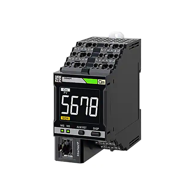
Motor Condition Monitoring Device
K6CM-CI
Quantifying the status of a three-phase
induction motor.
• The “comprehensive current diagnosis” can monitor not only
for motor problems, but also abnormal load-side conditions.
• Simply install a CT on the control panel enables monitoring.
• The software tool (set-up and simple monitoring tool) is also
provided.
• K6CM-CI2M is suitable for use in an excessive noise
environment such as using an inverter. Supports Modbus TCP
in addition to EtherNet/IP.
For the most recent information on models that have been certified for
safety standards, refer to your OMRON website.
System Configuration
Basic Configuration
Comprehensive current diagnosis type (K6CM-CI)
*1
Three-phase
power supply
K6CM-CIC (CT)
Any type of
single-phase
measurement
Single-phase
power supply
*2
2.9 m
Measurement
trigger signal
By keeping a computer or PLC
continuously connected, you can
monitor the state of a motor.
(pre-wired cable) *3
Object monitored
K6CM-CI
Output signal
(transistor output)
1.5 kW to 300 kW (400 V)
0.75 kW to 150 kW (200 V)
Built-in EtherNet/IP port
Dedicated tool
EtherNet/IP
LAN
Modbus TCP
Note : 1. Even without a computer, the alarm bar of the main unit notifies you of changes of motor state.
2. The degradation level may appear differently depending on the failure condition of the motor
or load, or depending on the installation condition.
*1. In an environment where the motor is driven by an inverter, if the degradation level 1 is used as the measurement value, it may not be possible
to monitor the motor or load abnormalities. Therefore, it is recommended to use the degradation level 2. Refer to the User's manual (N219) for
details.
*2. Since the frequency band of the harmonics of the drive frequency and the frequency band in which errors such as load imbalance and
misalignment appear are the same frequency band for a 2-pole meter, sensitivity may be reduced with degradation level 2.
*3. The CT cable cannot be extended.
1
�K6CM-CI
Ordering Information
List of Models
Monitoring type
Comprehensive current diagnosis type
Power supply voltage
Model
100 to 240 VAC
K6CM-CI2MA-EIP
24 VAC/VDC
K6CM-CI2MD-EIP
Applicable Relay
Model
CT (Order separately)
Rated primary-side current
5A
K6CM-CICB005
25 A
K6CM-CICB025
100 A
K6CM-CICB100
K6CM-CI
200 A
K6CM-CICB200
400 A
K6CM-CICB400
600 A
K6CM-CICB600
Note: 1. One sensor is combined with one main unit. A cable for connection is provided with the CT.
Select a CT that sets the current of the applicable motor within the measurement range.
To calculate the current, refer to Comprehensive Current Diagnosis Type Technical Data (Reference) on page 10.
2. The sensor applicable for CSA certification is K6CM-CICB@@@-C.
EtherNet/IP communications cable recommended parts
Use a Category 5 or higher STP cable (shielded twisted pair cable).
Cable with Connectors
Recommended
manufacturer
Item
Wire Gauge and Number of Pairs:
AWG26, 4-pair Cable
Cable Sheath material: LSZH *2
Cable length (m)
0.3
Cable with Connectors on Both Ends (RJ45/RJ45)
Standard RJ45 plug type *1
Cable color: Yellow *3
OMRON
Wire Gauge and Number of Pairs:
AWG22, 2-pair Cable
OMRON
XS6W-6LSZH8SS30CM-Y
0.5
XS6W-6LSZH8SS50CM-Y
1
XS6W-6LSZH8SS100CM-Y
2
XS6W-6LSZH8SS200CM-Y
3
XS6W-6LSZH8SS300CM-Y
5
Cable with Connectors on Both Ends (RJ45/RJ45)
Rugged RJ45 plug type *1
Cable color: Light blue
Model
XS6W-6LSZH8SS500CM-Y
0.3
XS5W-T421-AMD-K
0.5
XS5W-T421-BMD-K
1
XS5W-T421-CMD-K
2
XS5W-T421-DMD-K
5
XS5W-T421-GMD-K
10
XS5W-T421-JMD-K
*1. Cables with standard RJ45 plugs are available in the following lengths: 0.2 m, 0.3 m, 0.5 m, 1 m, 1.5 m, 2 m, 3 m, 5 m, 7.5 m, 10 m, 15 m, 20 m.
Cables with rugged RJ45 plugs are available in the following lengths: 0.3 m, 0.5 m, 1 m, 2 m, 3 m, 5 m, 10 m, 15 m.
For details, refer to the Industrial Ethernet Connectors Catalog (Cat. No. G019).
*2. The lineup features Low Smoke Zero Halogen cables for in-cabinet use and PUR cables for out-of-cabinet use.
*3. Cable colors are available in yellow, green, and blue. The last character of the model changes to "-G" or "-B".
Cable/Connector
Part name
Manufacturer
Cable
Hitachi Metals, Ltd.
NETSTAR-C5E SA 0.5 × 4P *
Model
RJ45 connector
Panduit Corporation
MPS588-C *
* It is recommended to use the cable and connector in combination described above.
Industrial switching hub (recommended parts)
Specifications
Product name
Industrial switching hub
2
Appearance
Function
Priority control (QoS): EtherNet/IP control data
priority
Failure detection: Broadcast storm /
LSI failure detection
10/100BASE-TX, Auto-Negotiation
No. of ports
Failure detection
function
Model
3
No
W4S1-03B
5
No
W4S1-05B
5
Yes
W4S1-05C
�K6CM-CI
Ratings and Specifications
List of Models
Ratings
Power
Supply
Input
Power supply voltage
K6CM-@@MA: 100 to 240 VAC, 50/60 Hz
K6CM-@@MD: 24 VAC, 50/60 Hz, 24 VDC
Allowable operating voltage range
85% to 110% of power supply voltage
Power supply frequency range
45 to 65 Hz
Power consumption
24 VAC/24 VDC: 3.2 VA/1.7 W max.
100 to 240 VAC: 6.1 VA max.
Current,
comprehensive current
diagnosis (CT)
Rated input current
Applicable motor type
Outputs
5 A, 25 A, 100 A, 200 A, 400 A, 600 A
Three-phase induction motor (Rated voltage 600 VAC max) *1
Output form
Transistor output
Output capacity
3-point
Output rating
Rated voltage: 24 VDC
Max. current: 50 mA, DC
Ambient operating temperature
-10 to +55°C (with no condensation or icing)
Storage temperature
-20 to +65°C (with no condensation or icing)
Ambient operating humidity
25% to 85% RH (with no condensation)
Storage humidity
25% to 85% RH (with no condensation)
Case color
Black
Case material
Polycarbonate UL94-V0
Altitude
2,000 m max.
Applicable wires
Stranded wires, solid wires, or ferrules
Applicable wire size
0.25 to 1.5 mm2 (AWG24 to 16)
Wire insertion force
8 N max. (AWG20)
Screwdriver insertion force
15 N max.
Wire stripping length
8 mm
Recommended flat-blade screwdriver
XW4Z-00B (Omron)
Current capacity
10 A (per pole)
Number of insertions
50 times
Weight
Approx. 200 g
Mounting
Mounts to DIN Track
screw mounting
Dimensions
45 (W) × 90 (H) × 90 (D) mm
Setting method
Communications settings from a dedicated tool via EtherNet/IP
Other functions
Display value selection, self-diagnosis error output, setting value initialization, operation integration
Accessories
Operation manual, CD-ROM (Motor condition monitoring Tool)
*1. Motors other than three-phase induction motors (synchronous motors, single phase motors, servo motors, and stepping motors) are excluded.
The rated voltage of the motor applicable for UL certification is 480 VAC.
3
�K6CM-CI
Characteristics
Measurement range
Current
Rating 5 A:
Rating 25 A:
Rating 100 A:
Rating 200 A:
Rating 400 A:
Rating 600 A:
Rated frequency:
1.00 to 5.00 A
5.0 to 25.0 A
20.0 to 100.0 A
40.0 to 200.0 A
80.0 to 400.0 A
120.0 to 600.0 A
20 to 80 Hz
Degradation level 1, degradation level 2: 0 to 999
Recommended frequency: 20 to 80 Hz *1
Measurement
absolute
accuracy
Current
Sampling cycle
Degradation level 1, degradation level 2, current: 5 s
Moving average frequency
External trigger
1, 2, 4, 8, 16, 32 times
External contact input
specification
Short-circuit: Residual voltage 1.5 V max.
Open:
Leakage current 0.1 mA max.
Current during shortcircuiting
Approx. 7 mA
Contact configuration: NPN open collector
Rated voltage:
24 VDC (maximum voltage: 26.4 VDC)
Max. current:
50 mA, DC
Transistor output
Alarm
±1.0% FS±1 digit (at 10 to 30°C, CT variation is not included) *2
Parameters that can be
output
Degradation level 1, degradation level 2, current
Expression method
Transistor output, alarm bar
Setting value
Current
Rating 5 A:
00.00 to 99.99 A
Rating 25 A/100 A/ 200 A/400 A/600 A: 0.0 to 999.9 A
Degradation level 1, degradation level 2: 0 to 9999
Hysteresis
10% width of setting value
Reset method
Manual reset/automatic reset (switchable)
* Manual return method: Press the ALMRST button
7-Segment digital display and single-shot display
Font height 14 mm
LCD display
Applicable
standards
Conforming standards
EN61010-2-030
Installation environment: Pollution degree 2, overvoltage category II, measurement category II
EMC
EN61326-1(EMI: Class A EMS: Industrial Location)
Current ± 10% F.S.
Safety standards
UL61010-2-030 (listing) *5 / CSA 22.2 No.14 Overvoltage category II
Korean Radio Waves Act (Act 10564)
RCM
EAC
Insulation resistance
20 MΩ min.
Between all external terminals and the case
Between all power supply terminals and all other terminals
Between all sensor connection terminals and trigger input terminal + output terminal + all EtherNet/IP ports
Dielectric strength
2,000 VAC for 1 minute
Between all external terminals and the case
Between all power supply terminals and all other terminals
Between all sensor connection terminals and trigger input terminal + output terminal + all EtherNet/IP ports
Vibration resistance
Vibration frequency 10 to 55 Hz, slice amplitude 0.35 mm in each of X, Y, Z directions 5 minute × 10
Shock resistance
100 m/s2, 3 times each in 6 directions along 3 axes
Degree of protection
LED display
Alarm bar
IP20
Red/Yellow/Green
MS, NS *3
Red/Green
Number of ports
1
Physical layer
Ethernet: Connector RJ45
Type
100BASE-TX
Ethernet
communications Transmission distance
(Maximum cable length)
*4
Topology
Protocol
100 m (Between hub and node)
Star type
EtherNet/IP
Modbus TCP
*1. When used at a frequency higher than 80 Hz, the tendency toward motor degradation is less noticeable.
*2. For the frequency characteristics of the CT, refer to the technical data on page 10.
*3. MS: Product status display, NS: Network status display.
*4. A tag data link timeout may occur with products manufactured on or before April 30, 2019, over a network system including nodes set for
multicast communications. Use the multicast blocking function of the switching hub to prevent multicast packets from reaching the K6CM.
*5. The rated voltage of the motor applicable for UL certification is 480 VAC.
4
�K6CM-CI
CT
Ratings and Specifications
Model *3
Item
K6CM-CICB005
K6CM-CICB025
K6CM-CICB100
K6CM-CICB200
K6CM-CICB400
K6CM-CICB600
Construction
Indoor split type
Primary-side rated current
5A
25 A
100 A
200 A
400 A
600 A
Measurement range *1
1 to 5 A
5 to 25 A
20 to 100 A
40 to 200 A
80 to 400 A
120 to 600 A
Rated voltage
600 VAC *4
Secondary-side rated current
Dedicated current
Secondary winding
3000 turns
6000 turns
9000 turns
Insulation resistance
Between output terminal and case: 50 MΩ min.
Dielectric strength
Between output terminal and case: 2,000 VAC, 1 minute
Protective element
7.5 V clamp element
Permissible attachment/removal
frequency
100 times
Attachable wire diameter *2
7.9 mm dia. max.
Operating temperature / humidity
range
-20 to +60°C, 25 to 85% (with no condensation or icing)
Storage temperature / humidity
range
-30 to +65°C, 25 to 85% (with no condensation or icing)
Supplied cable length
2.9 m (pre-wired cable)
Supplied cable
terminal
Main unit side
CT side
Degree of protection
9.5 mm dia. max.
14.5 mm dia. max.
24.0 mm dia. max.
35.5 mm dia. max.
Ferrule terminal
Round terminal
IP20
*1. Select a CT that brings the current of the applicable motor into the measurement range.
To calculate the current, refer to the technical data on page 10.
*2. When using a flat wire, be sure to refer to the external dimensions drawing of the CT before selection on page 8.
*3. The sensor applicable for CSA certification is K6CM-CICB@@@-C.
*4. The rated voltage of the motor applicable for UL certification is 480 VAC.
Motor condition monitoring Tool (Software included with main unit)
Operating Environment
Element
Supported OS
Specification
Windows 7, Windows 8.1, Windows 10 (32 bit/64 bit) (Japanese/English)
.NET
.NET Framework 4 and .NET Framework 3.5
CPU
1 GHz or more, 32 bit or 64 bit processor
Memory
1 GB or more, or 2 GB or more (for 64 bit)
HDD
Others
Available space of 16 GB or more, or 20 GB or more (for 64 bit)
Since this software is provided on a CD-ROM, a CD-ROM reading device must be available.
If data is to be collected, a LAN I/F must be available.
Functions/Specifications (For more details, refer to the catalog of each product.)
Item
Project
Number of files that can be created
Log file
CSV data format
Monitoring cycle
Number that can be
registered in one
project
Graphic display
Specification
No limit
5 second to 366 days
Number of motors (device groups)
10
Number of devices per motor (device group)
3 *1
Type of graph
Line graph
Display period *2
1 hour, 1 day, 1 month, 1 year
*1. One vibration and temperature type, one insulation resistance type, and one current comprehensive diagnosis type can be set for one motor.
*2. In the software tool version 1.2.0.0 and earlier, the graph display period can be set by selecting the tabs (1 hour, 1 day, 3 months, 6 months,
1 year, 2 years, 5 years, 10 years, 20 years).
In the software tool version 1.2.0.0 and later, you can move the graph in the time axis direction using the graph time axis movement.
5
�K6CM-CI
Connection Diagram
Terminal Diagram (Main Unit)
K6CM- CI M A -EIP
(1)
Sensor input
(1) Power voltage
CT input
A: 100 to 240 V AC
D: 24 V AC/DC
K6CM-CIC
(CT)
White
1
2
1
2
(No polarity)
1
3
2
4
7 8
9 10
Black
7
8
External trigger input
3
4
5V
680 Ω
0V
� +
Comparator
13 14
15 16
17 18
Output function
Transistor output
13 14
Interior
Do not use
6
15 16
Interior
17 18
Interior
�K6CM-CI
Nomenclature
Hook
Push-in Plus terminal
Push-in Plus terminal
· Unit power supply
· External trigger input
· Sensor input
2D code
Alarm bar
Measurement value units
(measurement type)
LCD display for measured
values and other values
Main unit status display
Current value, minimum value,
and maximum measurement value type
[ALM RST] key
Front operation part
[DISP] key
Product status display
Network status display
Push-in Plus terminal
· Transistor output
EtherNet/IP port
Name
Meaning
Alarm bar
A bar on which the color of the emitted
light changes according to the alarm
status.
It is indicated in the following colors during measurement/monitoring.
Green: Alarm status (normal)
Yellow: Alarm status (Warning)
Red: Alarm status (Critical)
The alarm bar is lit out in each of the following states:
When the power is OFF, when measurement is not being performed, and when a selfdiagnosis error has occurred, etc.
Measurement type
Indicates the type of the measured value
being displayed. The type can be
switched each time the [DISP] key is
pressed on the front operation part.
“Ci1”: Degradation level 1, “Ci2”: Degradation level2, “A”: Current
[ALM RST] key
Releases the latched alarm state.
The main use of this key is to release the latched and fixed alarm state after returning
from the fault state to the normal state.
[DISP] key
Switches the type of the measured value being displayed.
You can switch between display-fixed mode and display auto switching mode by long-pressing for 3 seconds.
Others
If two keys are simultaneously pressed and held for 5 seconds or longer, all settings of the main unit are reset to factory defaults.
Front
operation
part
The status of the main unit is indicated by
lighting of the LCD characters.
“MON”: Measurement / monitoring is being performed
“ERR”: A self-diagnosis error has occurred
“AGE”: Running Time notification (it is recommended to replace the product main unit)
13-14
Output of the alarm status (Warning).
Can be set to Normally Closed or
Normally Open.
When measurement/monitoring is in progress,
and the output method is Normally Closed
ON = Comprehensive alarm: Normal / OFF = Comprehensive alarm: Warning or Critical
and the output method is Normally Open
OFF = Comprehensive alarm: Normal / ON = Comprehensive alarm: Warning or Critical
15-16
Output of the alarm status (Critical).
Can be set to Normally Closed or
Normally Open.
When measurement/monitoring is in progress,
and the output method is Normally Closed
ON = Comprehensive alarm: Warning or Normal / OFF = Comprehensive alarm: Critical
and the output method is Normally Open
OFF = Comprehensive alarm: Warning or Normal / ON = Comprehensive alarm: Critical
17-18
Self-diagnosis error output.
OFF: A self-diagnosis error has occurred
ON: Other than the above
3-4
Input of the external contact signal to
control measurement timing.
You can use "Trigger Type" to specify whether measurement/monitoring continue for a
set time after starting by the rise or fall of the external contact, or are executed while the
external contact is ON.
You can also specify settings to enable selection of a trigger mode other than external
trigger. *1
Main unit status display
Transistor
output
External
trigger input
Note: Warning:
Indicates that it is time for maintenance.
Critical:
Indicates that it is time for replacement.
*1. Trigger modes other than external trigger
Always:
Trigger is not used. Measurement/monitoring are performed continuously after the power of the K6CM unit is turned on.
Internal trigger: Measurement/monitoring starts based on the relation between the measured value and set value (trigger level).
You can use "Trigger Type" to specify whether measurement/monitoring start and continue for a set time when the measured
value is over, or under, the set value (trigger level), or are executed while the measured value exceeds the set value (trigger
level).
Also, the external trigger function can be used only when the insulation resistance type is EIP CPU version 1.1 or higher.
7
�K6CM-CI
Dimensions
(Unit: mm)
List of Models
K6CM-CI
(1.9)
90
(4)
86
45
90
CT
K6CM-CICB005
K6CM-CICB025
33
22.9
28.9
39
CT Through-hole
Dimensions
25.3
10
7.4
CT Through-hole
Dimensions
3
10
R5
8.5
7.9
25.5
3
R5
9.5
R8
R7.5
41.3
5.57
48
7.5
40
40.5
K6CM-CICB100
K6CM-CICB200
44.9
55.9
29.4
37.4
CT Through-hole
Dimensions
30.5
16
CT Through-hole
Dimensions
3
35.5
24
R8
6
R10
14.511
24
14.2 R9
53.7
46
8
75.7
R8
52.5
�K6CM-CI
K6CM-CICB400
K6CM-CICB600
Cable supplied with CT
CT side
Product side
Contraction tube
62.5
73.5
CT Through-hole
Dimensions
37
35.5
R18.5
6
35.5
92.5
R13
2.9 m
The cable supplied with the CT is shipped in the connected state.
54
9
�K6CM-CI
Comprehensive Current Diagnosis Type Technical Data (Reference)
Use one CT per motor to detect current flowing into the motor. Select a CT that matches the motor capacity.
Maximum
measurement range
K6CM-CICB005
1.00 A to 5.00 A
1.00 A to 5.25 A
K6CM-CICB025
5.00 A to 25.00 A
5.00 A to 26.25 A
K6CM-CICB100
20 A to 100 A
20 A to 105 A
K6CM-CICB200
40 A to 200 A
40 A to 210 A
K6CM-CICB400
80 A to 400 A
80 A to 420 A
K6CM-CICB600
120 A to 600 A
120 A to 630 A
Note: At no load, the motor current is at approximately half rated load.
Select a CT that can cover the range of 50% to 100% of rated current.
CT type
Measurement range
Applicable motor
(200 VAC)
0.75 kW
1.5 kW to 5.5 kW
7.5 kW to 22 kW
30 kW to 45 kW
55 kW to 90 kW
110 kW to 150 kW
Applicable motor
(400 VAC)
1.5 kW to 2.2 kW
3.7 kW to 11 kW
15 kW to 45 kW
55 kW to 90 kW
110 kW to 200 kW
250 kW to 300 kW
Use the following expression when calculating the current value from the motor capacitance.
Motor capacitance (kW) × 1000
Current value of motor (A) =
Motor voltage (V) × √3 × Power factor (0.9) × Efficiency (0.8)
(Example) When a 5.5-kW motor is used at 200 V
Current value of motor =
5.5 × 1000
200 × √3 × 0.9 × 0.8
= 22 A
Therefore, the CT K6CM-CICB025 in which 22 A is within the measurement range is selected.
The measurement range is within 20 and 100 A even in the case of K6CM-CICB100, which means that 22 A is within the range and this model
can also be used. However, during selection, priority must be given to a CT having a small rated current value in order to realize more accurate
measurement.
Note: In the expression shown above, general values must be used for the power factor and efficiency, and the load factor must be 100%. However,
depending on the actual operating environment, the actual current value and measured value may be different. If the CT is used at a current value
that is below the lower-limit value of the measurement range of the CT, the measurement error of the degradation level will increase. Therefore, if
possible, measure the current during a steady-state operation with a clamp meter, etc., and select a CT corresponding to the current value.
10
�K6CM-CI
List of Parameters
Setting values
Parameter
Content
Degradation level alarm threshold value (Critical and Warning)
0 to 9999
Current alarm threshold value (Critical and Warning)
CT rating 5 A: 00.00 to 99.99 A
CT rating 25 A/100 A/200 A/400 A/600 A: 0.0 to 999.9 A
Main unit IP address
Sets the IP address of the main unit.
The default value is “192.168.250.10” (common to all models)
Software reset
Restarts the K6CM. Used to enable the settings after changing the setting values.
0 → 1: Execute
MAX/MIN reset
Initializes the MAX/MIN value.
0 → 1: Execute
Display value type
Sets which measurement value to display in the 7-segment display at the front of
the main unit.
0: PV (Present Value), 1: MIN, 2: MAX
Trigger mode *1
Sets the trigger mode.
0: At all times, 1: External trigger, 2: Internal trigger
Trigger type
Sets Rise, Fall, or Level in the case of an internal trigger or external trigger.
0: Rise, 1: Fall, 2: Level
Trigger level
Sets the trigger level when “Internal trigger” and the trigger type “Level” have been
selected.
Monitoring time
Sets the time for continuing measurement or monitoring in the case of an internal
trigger or external trigger, when the trigger type is either Rise or Fall.
Setting value: 0.1 to 600.0 s
Alarm latch
Sets whether to enable or disable the alarm latch function.
0: Disable (no latch), 1: Enable (latched)
Use Running Time
Sets whether or not to use the main unit residual amount function.
0: OFF (Do not use), 1: ON (Use)
Moving average times
Performs the averaging process for the past n-times of data including the
sampling data of that time, each time sampling of the measurement value is
performed.
0: OFF, 1: 2 times, 2: 4 times, 3: 8 times, 4: 16 times, 5: 32 times
Current range
Selects the connected CT.
0: 5 A, 1: 25 A, 2: 100 A, 3: 200 A, 4: 400 A, 5: 600 A
Transistor output method *2
0: Normally Closed/1: Normally Open
Monitoring delay time
Set the delay time from the trigger input to the start of measurement.
Setting value: 0.0 to 600.0 seconds.
*1. The external trigger function can be used only when the insulation resistance type is EIP CPU version 1.1 or higher.
*2. Can be used only with EIP CPU version 1.1 or higher.
11
�K6CM-CI
Measured values / Status data
Parameter
Degradation level (Present value, MIN, MAX)
Current (Present value, MIN, MAX)
10 to 100% of the rated value
Degradation level status
Current value status
Measurement CPU version
12
Content
Degradation level of the motor calculated by measuring the current
including the high-frequency component.
0 to 999
Bit 00: Present value measurement status
Bit 01: Present value input error
Bit 04: MAX value measurement status
Bit 05: MAX value input error
Bit 08: MIN value measurement status
Bit 09: MIN value input error
Bit 12: Individual alarm threshold value (Warning) setting
Bit 13: Individual alarm threshold value (Critical) setting
Measurement unit version
Main CPU version
Main unit version
EIP CPU version
EtherNet/IP unit version
Measurement status
1: Measurement/monitoring in progress,
0: Measurement/monitoring stopped
Running time status
The product of the operation time and internal temperature is
integrated, and ON is set if it reaches the design life.
1: Reached (Operation integration has reached 100%)
0: Not reached (Operation integration has not reached 100%)
Trigger input
Status of external trigger input.
1: ON, 0: OFF
TR1 (Transistor 1 output status)
Status of transistor 1.
1: ON, 0: OFF
TR2 (Transistor 2 output status)
Status of transistor 2.
1: ON, 0: OFF
TR3 (Transistor 3 output status)
Status of transistor 3.
1: ON, 0: OFF
Running time
Coefficient showing the extent of life of the main unit based on the
product of the operation time and internal temperature. Incremented in
units of 10% starting from 0%.
0000 hex to 0064 hex (0 to 100)
Trigger frequency
Total integrated number of external triggers and internal triggers.
Incremented by 1 after every 100 times.
0 to 65535
Threshold value setting of integrated alarm (Warning)
State when the measurement value is “Warning”.
Threshold value setting of integrated alarm (Critical)
State when the measurement value is “Critical”.
Degradation level alarm (Critical and Warning)
ON, OFF
Current alarm (Critical and Warning)
ON, OFF
�Motor Condition Monitoring Device
K6CM-VB
Quantifying the status of a three-phase
induction motor.
• Bearing failures can be detected quickly.
• Using manual allows you to set the default values for the alarm
threshold.
• An integrated sensor can measure vibration and temperature
simultaneously.
• The software tool (set-up and simple monitoring tool) is also
provided.
• Supports Modbus TCP in addition to EtherNet/IP.
For the most recent information on models that have been certified for
safety standards, refer to your OMRON website.
System Configuration
Basic Configuration
Vibration & temperature type (K6CM-VB)
Inverter *1
(Measurement is also
possible without an inverter)
Three-phase
power supply
2.6 m
(pre-wired cable)
K6CM-VBS1
(pre-amplifier)
Connector
Single-phase
power supply
0.3 m
(pre-wired cable)
1 m (extendable to 100 m) *2
K6CM-VBS1
(Sensor head)
Tighten screw
perpendicularly
directly above
rotation shaft
(load side)
*3
Measurement
trigger signal
Output signal
(transistor output)
By keeping a computer or PLC
continuously connected, you can
monitor the state of a motor.
Object monitored
K6CM-VB
Built-in EtherNet/IP port
Dedicated tool
EtherNet/IP
LAN
Modbus TCP *4
Note: Even without a computer, the alarm bar of the main unit notifies you of changes of motor state.
*1. When you use an inverter to drive the motor, you may not be able to check the degradation tendency of the motor. In the conditions below,
acceleration fluctuations tend to occur more frequently.
• The frequency is stable at an inverter drive frequency of 50 Hz or higher.
• The inverter carrier frequency is stable at 12.5 KHz or higher.
Test in the actual installation environment before use.
*2. For extension cable, use shielded twisted pair cable with wire gauges of AWG24 to 16.
*3. When using adhesive attachment, sensor head can be attached with adhesive attachment.
*4. Can be used only with EIP CPU version 1.2 or higher.
13
�K6CM-VB
Ordering Information
List of Models
Monitoring type
Vibration & temperature type
Power supply voltage
Model
100 to 240 VAC
K6CM-VBMA-EIP
24 VAC/VDC
K6CM-VBMD-EIP
Input part
Vibration & temperature sensor (Order separately)
Appearance
(pre-amplifier)
Appearance
(sensor head)
Attachment part
Applicable Relay
M6 screw
K6CM-VB
Model
K6CM-VBS1
Note: One sensor is combined with one main unit.
The vibration and temperature sensor consists of a sensor head and a pre-amplifier.
A magnet is provided for the easy attachment of the vibration and temperature sensor.
Use to determine the position to be measured. Note that measurement accuracy is not guaranteed in the case of magnet mounting.
Vibration and temperature sensor Adhesive attachment (option)
Appearance
Model
K6CM-VBSAT1
14
�K6CM-VB
EtherNet/IP communications cable recommended parts
Use a Category 5 or higher STP cable (shielded twisted pair cable).
Cable with Connectors
Recommended
manufacturer
Item
Wire Gauge and Number of Pairs:
AWG26, 4-pair Cable
Cable Sheath material: LSZH *2
Wire Gauge and Number of Pairs:
AWG22, 2-pair Cable
Cable with Connectors on Both Ends
(RJ45/RJ45)
Standard RJ45 plug type *1
Cable color: Yellow *3
Cable with Connectors on Both Ends
(RJ45/RJ45)
Rugged RJ45 plug type *1
Cable color: Light blue
Cable length (m)
Model
0.3
XS6W-6LSZH8SS30CM-Y
0.5
XS6W-6LSZH8SS50CM-Y
1
XS6W-6LSZH8SS100CM-Y
2
XS6W-6LSZH8SS200CM-Y
3
XS6W-6LSZH8SS300CM-Y
5
XS6W-6LSZH8SS500CM-Y
OMRON
0.3
XS5W-T421-AMD-K
0.5
XS5W-T421-BMD-K
1
XS5W-T421-CMD-K
OMRON
2
XS5W-T421-DMD-K
5
XS5W-T421-GMD-K
10
XS5W-T421-JMD-K
*1. Cables with standard RJ45 plugs are available in the following lengths: 0.2 m, 0.3 m, 0.5 m, 1 m, 1.5 m, 2 m, 3 m, 5 m, 7.5 m, 10 m, 15 m, 20 m.
Cables with rugged RJ45 plugs are available in the following lengths: 0.3 m, 0.5 m, 1 m, 2 m, 3 m, 5 m, 10 m, 15 m.
For details, refer to the Industrial Ethernet Connectors Catalog (Cat. No. G019).
*2. The lineup features Low Smoke Zero Halogen cables for in-cabinet use and PUR cables for out-of-cabinet use.
*3. Cable colors are available in yellow, green, and blue. The last character of the model changes to "-G" or "-B".
Cable/Connector
Part name
Cable
RJ45 connector
Manufacturer
Hitachi Metals, Ltd.
Panduit Corporation
Model
NETSTAR-C5E SA 0.5 × 4P *
MPS588-C *
* It is recommended to use the cable and connector in combination described above.
Industrial switching hub (recommended parts)
Specifications
Product name
Industrial switching hub
Appearance
Function
Priority control (QoS): EtherNet/IP control data
priority
Failure detection: Broadcast storm /
LSI failure detection
10/100BASE-TX, Auto-Negotiation
No. of ports
Failure
detection
function
Model
3
No
W4S1-03B
5
No
W4S1-05B
5
Yes
W4S1-05C
15
�K6CM-VB
Ratings and Specifications
List of Models
Ratings
Power
Supply
Input
Power supply voltage
K6CM-@@MA: 100 to 240 VAC, 50/60 Hz
K6CM-@@MD: 24 VAC, 50/60 Hz, 24 VDC
Allowable operating voltage range
85% to 110% of power supply voltage
Power supply frequency range
45 to 65 Hz
Power consumption
24 VAC/24 VDC: 3.8 VA/2.1 W max.
100 to 240 VAC: 7.1 VA max.
Vibrations
(vibration sensor)
Detection frequency
10 Hz to 10 kHz
Max. operating
acceleration
10 G
Applicable motor type
Outputs
Three-phase induction motor (Rated voltage 600 V or less) *
Output form
Transistor output
Output capacity
3-point
Output rating
Rated voltage: 24 VDC
Max. current: 50 mA, DC
Ambient operating temperature
-10 to +55°C (with no condensation or icing)
Storage temperature
-20 to +65°C (with no condensation or icing)
Ambient operating humidity
25% to 85% RH (with no condensation)
Storage humidity
25% to 85% RH (with no condensation)
Case color
Black
Case material
Polycarbonate UL94-V0
Altitude
2,000 m max.
Applicable wires
Stranded wires, solid wires, or ferrules
Applicable wire size
0.25 to 1.5 mm2 (AWG24 to 16)
Wire insertion force
8 N max. (AWG20)
Screwdriver insertion force
15 N max.
Wire stripping length
8 mm
Recommended flat-blade screwdriver
XW4Z-00B (Omron)
Current capacity
10 A (per pole)
Number of insertions
50 times
Weight
Approx. 200 g
Mounting
Mounts to DIN Track
screw mounting
Dimensions
45 (W) × 90 (H) × 90 (D) mm
Setting method
Communications settings from a dedicated tool via EtherNet/IP
Other functions
Display value selection, self-diagnosis error output, setting value initialization, operation integration
Accessories
Operation manual, CD-ROM (Motor condition monitoring Tool)
* Motors other than three-phase induction motors (synchronous motors, single phase motors, servo motors, and stepping motors) are excluded.
16
�K6CM-VB
Characteristics
Measurement range
Measurement
absolute
accuracy
Acceleration
Temperature
Sampling cycle
Moving average frequency
External contact input
specification
External trigger
Current during shortcircuiting
Parameters that can be
output
Expression method
Setting value
Hysteresis
Reset method
LCD display
Conforming standards
Applicable
standards
Short-circuit: Residual voltage 1.5 V max.
Open:
Leakage current 0.1 mA max.
Approx. 7 mA
Contact configuration: NPN open collector
Rated voltage:
24 VDC (maximum voltage: 26.4 VDC)
Max. current:
50 mA, DC
Transistor output
Alarm
Acceleration: 0.05 to 9.99 G, Velocity: 0.90 to 45.00 mm/s,
Motor temperature: 0 to 80°C, Differential temperature: 0 to 80°C
±3 dB±2 digit (at 25°C)
Motor temperature: ±3°C±2 digit (±6°F±2 digit) *1
Temperature Gap: ±6°C±2 digit (±12°F±2 digit) *1
Acceleration: 50 ms, Velocity: 0.5 s, Temperature: 0.5 s
1, 2, 4, 8, 16, 32 times
EMC
Safety standards
Insulation resistance
Dielectric strength
Vibration resistance
Shock resistance
Degree of protection
Alarm bar
LED display
MS, NS *2
Number of ports
Physical layer
Type
Ethernet
communications Transmission distance
(Maximum cable length)
*3
Topology
Protocol
Degradation level, current
Transistor output, alarm bar
Acceleration: 0.00 to 99.99 G, Velocity: 0.00 to 99.99 mm/s,
Motor temperature: 0 to 9999 deg., Differential temperature: 0 to 9999 deg.
10% width of setting value
Manual reset/automatic reset (switchable)
* Manual return method: Press the ALMRST button
7-Segment digital display and single-shot display
Font height 14 mm
EN61010-2-030
Installation environment: Pollution degree 2, overvoltage category II, measurement category II
EN61326-1(EMI: Class A EMS: Industrial Location)
Acceleration ± 0.1G, Velocity ±2.25mm/s, Temperature ± 6°C
UL61010-2-030 (listing)
Korean Radio Waves Act (Act 10564)
RCM
EAC
20 MΩ min.
Between all external terminals and the case
Between all power supply terminals and all other terminals
Between all sensor connection terminals and trigger input terminal + output terminal + all EtherNet/IP ports
2,000 VAC for 1 minute
Between all external terminals and the case
Between all power supply terminals and all other terminals
Between all sensor connection terminals and trigger input terminal + output terminal + all EtherNet/IP ports
Vibration frequency 10 to 55 Hz, slice amplitude 0.35 mm in each of X, Y, Z directions 5 minute × 10
100 m/s2, 3 times each in 6 directions along 3 axes
IP20
Red/Yellow/Green
Red/Green
1
Ethernet: Connector RJ45
100BASE-TX
100 m (Between hub and node)
Star type
EtherNet/IP
Modbus TCP *4
*1. Except when an adhesive attachment is used.
*2. MS: Product status display, NS: Network status display.
*3. A tag data link timeout may occur with products manufactured on or before April 30, 2019, over a network system including nodes set for
multicast communications. Use the multicast blocking function of the switching hub to prevent multicast packets from reaching the K6CM.
*4. Can be used only with EIP CPU version 1.2 or higher.
17
�K6CM-VB
Input part
Vibration & temperature sensor
Ratings
Item
Model
Power supply voltage
Sensor head
K6CM-VBS1
Supplied from K6CM-VB
Max. acceleration
10 G
Ambient operating temperature
Pre-amplifier: -10 to +55°C (with no condensation or icing)
Sensor head: -10 to +80°C (with no condensation or icing)
Storage temperature
Pre-amplifier: -20 to +65°C (with no condensation or icing)
Sensor head: -20 to +90°C (with no condensation or icing)
Ambient operating humidity
25% to 85% RH (with no condensation)
Storage humidity
25% to 85% RH (with no condensation)
Altitude
2,000 m max.
Case color
Pre-amplifier: Black
Sensor head: Silver
Case material
Pre-amplifier: Polycarbonate UL94-V0
Sensor head: Aluminum alloy (ADC12) / Zinc die casting (ZDC2) (the threaded part is Steel (S45C))
Weight
Pre-amplifier: Approx. 210 g (including cables)
Sensor head: Approx. 40 g (including cables)
Mounting
Pre-amplifier: DIN rail mounting, screw mounting
Sensor head: Screw mounting
Between pre-amplifier and sensor head: Connector connection (smart click connector)
Wire length
Between pre-amplifier and sensor head: 2.6 m+0.3 m (cannot be extended)
Between pre-amplifier and main unit: 1 m Can be extended up to a maximum length of 100 m *
* When extending the cable on the pre-amplifier side, use shielded twisted pair cable with wire gauges of AWG24 to 16.
Characteristics
Item
Model
Measurement range
Applicable
standards
Conforming
standards
EN 61010-2-030
Installation environment: Pollution degree 2, overvoltage category II, measurement category II
EMC
EN 61326-1 (EMI: Class A EMS: Industrial Location)
Safety standards
UL 61010-2-030 (listing)
RCM
EAC
Insulation resistance
20 MΩ min.
Dielectric strength
Vibration
resistance
Shock resistance
Degree of
protection
LED display
18
K6CM-VBS1
Specified in main unit “Characteristics”
500 VAC for one minute
Pre-amplifier
Vibration frequency 10 to 55 Hz, slice amplitude 0.35 mm in each of X, Y, Z directions 5 minute × 10
Sensor head
Vibration frequency 10 to 55 Hz, slice amplitude 0.35 mm in each of X, Y, Z directions 5 minute × 10
Pre-amplifier
100 m/s2, 3 times each in 6 directions along 3 axes
Sensor head
100 m/s2, 3 times each in 6 directions along 3 axes
Pre-amplifier
IP20 (excluding the sensor-side cable)
Sensor head
Conforming to IP67G (JIS C 0920 : 2003, Appendix 1)
Pre-amplifier PWR: Green, ERR: Red, COM: Orange
�K6CM-VB
Motor condition monitoring Tool (Software included with main unit)
Operating Environment
Element
Supported OS
Specification
Windows 7, Windows 8.1, Windows 10 (32 bit/64 bit) (Japanese/English)
.NET
.NET Framework 4 and .NET Framework 3.5
CPU
1 GHz or more, 32 bit or 64 bit processor
Memory
1 GB or more, or 2 GB or more (for 64 bit)
HDD
Others
Available space of 16 GB or more, or 20 GB or more (for 64 bit)
Since this software is provided on a CD-ROM, a CD-ROM reading device must be available.
If data is to be collected, a LAN I/F must be available.
Functions/Specifications (For more details, refer to the catalog of each product.)
Item
Project
Number of files that can be created
Log file
CSV data format
Monitoring cycle
Number that can be
registered in one
project
Graphic display
Specification
No limit
5 second to 366 days
Number of motors (device groups)
10
Number of devices per motor (device group)
3 *1
Type of graph
Line graph
Display period *2
1 hour, 1 day, 1 month, 1 year
*1. One vibration and temperature type, one insulation resistance type, and one current comprehensive diagnosis type can be set for one motor.
*2. In the software tool version 1.2.0.0 and earlier, the graph display period can be set by selecting the tabs (1 hour, 1 day, 3 months, 6 months,
1 year, 2 years, 5 years, 10 years, 20 years).
In the software tool version 1.2.0.0 and later, you can move the graph in the time axis direction using the graph time axis movement.
19
�K6CM-VB
Connection Diagram
Terminal Diagram (Main Unit)
K6CM- VB M A -EIP
(1)
(2)
(1) Sensor input
(2) Power voltage
A: 100 to 240 V AC
VB: Vibration and
temperature sensor input
D: 24 V AC/DC
K6CM-VBS
(pre-amplifier)
1
2
1
2
(No polarity)
1
3
2
4
7 8
9 10
Red/
white
Black
Red
7 8
9 10
Black
/white
External trigger input
3
4
5V
680 Ω
0V
− +
Comparator
13 14
15 16
17 18
Output function
Transistor output
13 14
Interior
Do not use
20
15 16
Interior
17 18
Interior
�K6CM-VB
Nomenclature
Hook
Push-in Plus terminal
Push-in Plus terminal
· Unit power supply
· External trigger input
· Sensor input
2D code
Alarm bar
Measurement value units
(measurement type)
LCD display for measured
values and other values
Main unit status display
Current value, minimum value,
and maximum measurement value type
[ALM RST] key
Front operation part
[DISP] key
Product status display
Network status display
Push-in Plus terminal
· Transistor output
EtherNet/IP port
Name
Meaning
Alarm bar
A bar on which the color of the emitted
light changes according to the alarm
status.
It is indicated in the following colors during measurement/monitoring.
Green: Alarm status (normal)
Yellow: Alarm status (Warning)
Red: Alarm status (Critical)
The alarm bar is lit out in each of the following states:
When the power is OFF, when measurement is not being performed, and when a selfdiagnosis error has occurred, etc.
Measurement type
Indicates the type of the measured value
being displayed. The type can be
switched each time the [DISP] key is
pressed on the front operation part.
“G”: Acceleration, “mm/s”: Velocity, “T”; Motor temperature,
“ T”: Temperature Gap (difference between motor temperature and room
temperature)
[ALM RST] key
Releases the latched alarm state.
The main use of this key is to release the latched and fixed alarm state after returning
from the fault state to the normal state.
[DISP] key
Switches the type of the measured value being displayed.
You can switch between display-fixed mode and display auto switching mode by long-pressing for 3 seconds. *1
Others
If two keys are simultaneously pressed and held for 5 seconds or longer, all settings of the main unit are reset to factory defaults.
Front
operation
part
The status of the main unit is indicated by
lighting of the LCD characters.
“MON”: Measurement / monitoring is being performed
“ERR”: A self-diagnosis error has occurred
“AGE”: Running Time notification (it is recommended to replace the product main unit)
13-14
Output of the alarm status (Warning).
Can be set to Normally Closed or
Normally Open.
When measurement/monitoring is in progress,
and the output method is Normally Closed
ON = Comprehensive alarm: Normal / OFF = Comprehensive alarm: Warning or Critical
and the output method is Normally Open
OFF = Comprehensive alarm: Normal / ON = Comprehensive alarm: Warning or Critical
15-16
Output of the alarm status (Critical).
Can be set to Normally Closed or
Normally Open.
When measurement/monitoring is in progress,
and the output method is Normally Closed
ON = Comprehensive alarm: Warning or Normal / OFF = Comprehensive alarm: Critical
and the output method is Normally Open
OFF = Comprehensive alarm: Warning or Normal / ON = Comprehensive alarm: Critical
17-18
Self-diagnosis error output.
OFF: A self-diagnosis error has occurred
ON: Other than the above
3-4
Input of the external contact signal to
control measurement timing.
You can use "Trigger Type" to specify whether measurement/monitoring continue for a
set time after starting by the rise or fall of the external contact, or are executed while the
external contact is ON.
You can also specify settings to enable selection of a trigger mode other than external
trigger. *2
Main unit status display
Transistor
output
External
trigger input
Note: Warning:
Indicates that it is time for maintenance.
Critical:
Indicates that it is time for replacement.
*1. Can be used only with EIP CPU version 1.2 or higher.
*2. Trigger modes other than external trigger
Always:
Trigger is not used. Measurement/monitoring are performed continuously after the power of the K6CM unit is turned on.
Internal trigger: Measurement/monitoring starts based on the relation between the measured value and set value (trigger level).
You can use "Trigger Type" to specify whether measurement/monitoring start and continue for a set time when the measured
value is over, or under, the set value (trigger level), or are executed while the measured value exceeds the set value (trigger
level).
Also, the external trigger function can be used only when the insulation resistance type is EIP CPU version 1.1 or higher.
21
�K6CM-VB
Dimensions
(Unit: mm)
List of Models
K6CM-VB
(1.9)
90
(4)
86
45
90
Vibration & temperature sensor
K6CM-VBS1
Pre-amplifier
M12 (smart click connector)
35
90
35
2,400
(40.7)
M12 (smart click connector)
31
(4)
Sensor head
Mounting hole dimensions
M6 screw
M12 (smart click connector)
17
A
A´
M6
Surface finish
20 mm dia. or more
17
8
17
9 mm or more
31
300
(44.7)
A-A´ cross section
How to Attach the Sensor Head
Tap the outer casing (*) of the motor perpendicularly for an M6
screw, and screw the vibration sensor head into the tap.
* The position above the bearing on the load side is recommended.
K6CM-VBSAT1
Adhesive attachment
Use the adhesive attachment if the motor cannot be tapped.
Sensor head
22
12
M6 screw
How to Attach the Sensor Head
Prepare a flat surface with a radius of at least 25 mm on the motor outer
casing (*).
Attach the attachment to the flat surface you prepared with an adhesive.
Screw the vibration sensor head into the attachment.
* The position above the bearing on the load side is recommended.
24 dia.
Material: Stainless steel
22
C0.5
C0.5
�K6CM-VB
Vibration & Temperature Type: Technical Data
Pairing of sensor head and pre-amplifier
The sensor head and the pre-amplifier are calibrated and inspected as a set at the factory shipment. Be sure to use them with the combination
shipped. The sensor head cannot be replaced.
To verify the combination, check the serial numbers on the label of the sensor head and the label of the pre-amplifier. The same serial number
means the correct combination.
If you change the combination of factory shipping conditions and then use them, the value of acceleration and the value of velocity will be
inconsistent, so measurement cannot be correctly monitored.
(01)04549734178730
(21)1342177281
MES:Ver.1.0
(01)04549734178730
(21)1342177281
MES:Ver.1.0
The number following (21) in the second line
is the serial number.
Make sure that this number on the sensor
head's label matches the number on the
pre-amplifier's label.
OMRON Corporation
MADE IN JAPAN
23
�K6CM-VB
List of Parameters
Setting values
Parameter
Acceleration alarm threshold value (Critical and Warning)
Content
0.00 to 99.99 G
Velocity alarm threshold value (Critical and Warning)
0.00 to 99.99 mm/s
Motor temperature alarm threshold value (Critical and Warning)
0 to 9999 deg.
Temperature gap alarm threshold value (Critical and Warning)
0 to 9999 deg.
Main unit IP address
Sets the IP address of the main unit.
The default value is “192.168.250.10” (common to all models)
Software reset
Restarts the K6CM. Used to enable the settings after changing the setting values.
0 → 1: Execute
MAX/MIN reset
Initializes the MAX/MIN value.
0 → 1: Execute
Display value type
Sets which measurement value to display in the 7-segment display at the front of
the main unit.
0: PV (Present Value), 1: MIN, 2: MAX
Trigger mode *1
Sets the trigger mode.
0: At all times, 1: External trigger, 2: Internal trigger
Trigger type
Sets Rise, Fall, or Level in the case of an internal trigger or external trigger.
0: Rise, 1: Fall, 2: Level
Trigger level
Sets the trigger level when “Internal trigger” and the trigger type “Level” have been
selected.
Monitoring time
Sets the time for continuing measurement or monitoring in the case of an internal
trigger or external trigger, when the trigger type is either Rise or Fall.
Setting value: 0.1 to 600.0 s
Alarm latch
Sets whether to enable or disable the alarm latch function.
0: Disable (no latch), 1: Enable (latched)
Use Running Time
Sets whether or not to use the main unit residual amount function.
0: OFF (Do not use), 1: ON (Use)
Moving average times
Performs the averaging process for the past n-times of data including the
sampling data of that time, each time sampling of the measurement value is
performed.
0: OFF, 1: 2 times, 2: 4 times, 3: 8 times, 4: 16 times, 5: 32 times
Temperature unit
Sets the temperature unit.
0: °C, 1: °F
Transistor output method *2
0: Normally Closed/1: Normally Open
Monitoring delay time *3
Set the delay time from the trigger input to the start of measurement.
Set value: 0.0 to 600.0 seconds.
*1. The external trigger function can be used only when the insulation resistance type is EIP CPU version 1.1 or higher.
*2. Can be used only with EIP CPU version 1.1 or higher.
*3. Can be used only with EIP CPU version 1.2 or higher.
24
�K6CM-VB
Measured values / Status data
Parameter
Content
Acceleration (Present value, MIN, MAX)
0.00 to 9.99 G
Velocity (Present value, MIN, MAX)
0.00 to 45.00 mm/s
Motor temperature
0 to 80°C (32 to 176°F)
Temperature gap (Difference between motor temperature and room
temperature)
0 to 80°C (32 to 176°F)
Acceleration status
Temperature gap status
Bit 00: Present value measurement status
Bit 01: Present value input error
Bit 04: MAX value measurement status
Bit 05: MAX value input error
Bit 08: MIN value measurement status
Bit 09: MIN value input error
Bit 12: Individual alarm threshold value (Warning) setting
Bit 13: Individual alarm threshold value (Critical) setting
Measurement CPU version
Measurement unit version
Main CPU version
Main unit version
EIP CPU version
EtherNet/IP unit version
Measurement status
1: Measurement/monitoring in progress,
0: Measurement/monitoring stopped
Running time status
The product of the operation time and internal temperature is
integrated, and ON is set if it reaches the design life.
1: Reached (Operation integration has reached 100%)
0: Not reached (Operation integration has not reached 100%)
Trigger input
Status of external trigger input.
1: ON, 0: OFF
TR1 (Transistor 1 output status)
Status of transistor 1.
1: ON, 0: OFF
TR2 (Transistor 2 output status)
Status of transistor 2.
1: ON, 0: OFF
TR3 (Transistor 3 output status)
Status of transistor 3.
1: ON, 0: OFF
Running time
Coefficient showing the extent of life of the main unit based on the
product of the operation time and internal temperature. Incremented in
units of 10% starting from 0%.
0000 hex to 0064 hex (0 to 100)
Trigger frequency
Total integrated number of external triggers and internal triggers.
Incremented by 1 after every 100 times.
0 to 65535
Velocity status
Motor temperature status
Threshold value setting of integrated alarm (Warning)
State when the measurement value is “Warning”.
Threshold value setting of integrated alarm (Critical)
State when the measurement value is “Critical”.
Acceleration alarm (Critical and Warning)
ON, OFF
Velocity alarm (Critical and Warning)
ON, OFF
Motor temperature alarm (Critical and Warning)
ON, OFF
Temperature gap alarm (Critical and Warning)
ON, OFF
25
�MEMO
26
�Motor Condition Monitoring Device
K6CM-IS
Quantifying the status of a three-phase
induction motor.
* ZCT (IRT) is compatible with UL Recognition
• The “insulation resistance” can be always monitored in live
wire states.
• Simply attaching the ZCT to the control panel enables
monitoring.
• The insulation resistance can be measured even when an
inverter is used.
• The software tool (set-up and simple monitoring tool) is also
provided.
• Supports Modbus TCP in addition to EtherNet/IP.
For the most recent information on models that have been certified for
safety standards, refer to your OMRON website.
27
�K6CM-IS
System Configuration
Basic Configuration
Insulation resistance type (K6CM-IS)
Three-phase, three-conductor, S-phase ground
Inverter *1
(Measurement is also
possible without an inverter)
Inverter secondary-side voltage
40 m max. (From ZCT to motor.
Extendable in some conditions) *2
Three-phase R
S
power supply T
1m
K6CM-ISZBI52
(pre-wired cable)
Single-phase
power supply
Object monitored
Measurement
trigger signal
1 m (extendable to 100 m) *3
By keeping a computer or PLC
continuously connected, you can
monitor the state of a motor.
(pre-wired cable)
Output signal
(transistor output)
K6CM-IS
Dedicated tool
7.5 kW or less
(Measurement error
increases when this
value is exceeded.)
Built-in EtherNet/IP port
EtherNet/IP
LAN
Modbus TCP *4
Note: Even without a computer, the alarm bar of the main unit notifies you of changes of motor state.
*1. Measurement may not be possible depending on the drive frequency of the inverter. See the User's Manual (N219) for more information.
*2. For details, refer to the technical data on page 36.
*3. For extension cable, use shielded twisted pair cable with wire gauges of AWG24 to 16.
*4. Can be used only with EIP CPU version 1.2 or higher.
Three-phase, four-conductor, N-phase ground
Note: When an inverter is used with three-phase, four-conductor,
N-phase ground, correct measurement is not possible
40 m max. (From ZCT to motor.
Extendable in some conditions) *1
R
S
T
N
1m
(pre-wired cable)
K6CM-ISZBI52
Object monitored
Single-phase
power supply
Measurement
trigger signal
1 m (extendable to 100 m) *2
By keeping a computer or PLC
continuously connected, you can
monitor the state of a motor.
Dedicated tool
(pre-wired cable)
K6CM-IS
Output signal
(transistor output)
Built-in EtherNet/IP port
EtherNet/IP
LAN
Modbus TCP *3
Note: Even without a computer, the alarm bar of the main unit notifies you of changes of motor state.
*1. For details, refer to the technical data on page 36.
*2. For extension cable, use shielded twisted pair cable with wire gauges of AWG24 to 16.
*3. Can be used only with EIP CPU version 1.2 or higher.
28
7.5 kW or less
(Measurement error
increases when this
value is exceeded.)
�K6CM-IS
Ordering Information
List of Models
Monitoring type
Insulation resistance type
Power supply voltage
Model
100 to 240 VAC
K6CM-ISMA-EIP
24 VAC/VDC
K6CM-ISMD-EIP
ZCT (IRT) (Order separately)
Rated voltage
Through hole dia.
(mm)
Applicable Relay
Model
200 to 480 VAC
52 dia.
K6CM-IS
K6CM-ISZBI52
Note: One sensor is combined with one main unit.
ZCT (IRT) is the abbreviation for Zero Current Transfer (Insulation Resistance Transfer).
A cable for connection is provided with the ZCT (IRT).
EtherNet/IP communications cable recommended parts
Use a Category 5 or higher STP cable (shielded twisted pair cable).
Cable with Connectors
Recommended
manufacturer
Item
Wire Gauge and Number of Pairs:
AWG26, 4-pair Cable
Cable Sheath material: LSZH *2
Wire Gauge and Number of Pairs:
AWG22, 2-pair Cable
Cable with Connectors on Both Ends
(RJ45/RJ45)
Standard RJ45 plug type *1
Cable color: Yellow *3
Cable with Connectors on Both Ends
(RJ45/RJ45)
Rugged RJ45 plug type *1
Cable color: Light blue
Cable length (m)
Model
0.3
XS6W-6LSZH8SS30CM-Y
0.5
XS6W-6LSZH8SS50CM-Y
1
XS6W-6LSZH8SS100CM-Y
2
XS6W-6LSZH8SS200CM-Y
3
XS6W-6LSZH8SS300CM-Y
5
XS6W-6LSZH8SS500CM-Y
OMRON
0.3
XS5W-T421-AMD-K
0.5
XS5W-T421-BMD-K
1
XS5W-T421-CMD-K
OMRON
2
XS5W-T421-DMD-K
5
XS5W-T421-GMD-K
10
XS5W-T421-JMD-K
*1. Cables with standard RJ45 plugs are available in the following lengths: 0.2 m, 0.3 m, 0.5 m, 1 m, 1.5 m, 2 m, 3 m, 5 m, 7.5 m, 10 m, 15 m, 20 m.
Cables with rugged RJ45 plugs are available in the following lengths: 0.3 m, 0.5 m, 1 m, 2 m, 3 m, 5 m, 10 m, 15 m.
For details, refer to the Industrial Ethernet Connectors Catalog (Cat. No. G019).
*2. The lineup features Low Smoke Zero Halogen cables for in-cabinet use and PUR cables for out-of-cabinet use.
*3. Cable colors are available in yellow, green, and blue. The last character of the model changes to "-G" or "-B".
Cable/Connector
Part name
Cable
RJ45 connector
Manufacturer
Hitachi Metals, Ltd.
Panduit Corporation
Model
NETSTAR-C5E SA 0.5 × 4P *
MPS588-C *
* It is recommended to use the cable and connector in combination described above.
Industrial switching hub (recommended parts)
Specifications
Product name
Industrial switching hub
Appearance
Function
Priority control (QoS): EtherNet/IP control data
priority
Failure detection: Broadcast storm /
LSI failure detection
10/100BASE-TX, Auto-Negotiation
No. of ports
Failure
detection
function
Model
3
No
W4S1-03B
5
No
W4S1-05B
5
Yes
W4S1-05C
29
�K6CM-IS
Ratings and Specifications
List of Models
Ratings
Power
Supply
Input
Power supply voltage
K6CM-@@MA: 100 to 240 VAC, 50/60 Hz
K6CM-@@MD: 24 VAC, 50/60 Hz, 24 VDC
Allowable operating voltage range
85% to 110% of power supply voltage
Power supply frequency range
45 to 65 Hz
Power consumption
24 VAC/24 VDC: 3.7 VA/2.0 W max.
100 to 240 VAC: 6.2 VA max.
Insulation resistance
(ZCT (IRT))
Rated input voltage
Rated path current
Applicable motor type
Outputs
(Line voltage) 200 to 480 VAC, 50 Hz/60 Hz
300 AAC
Three-phase induction motor (Rated voltage 480 V or less) *
Output form
Transistor output
Output capacity
3-point
Output rating
Rated voltage: 24 VDC
Max. current: 50 mA, DC
Ambient operating temperature
-10 to +55°C (with no condensation or icing)
Storage temperature
-20 to +65°C (with no condensation or icing)
Ambient operating humidity
25% to 85% RH (with no condensation)
Storage humidity
25% to 85% RH (with no condensation)
Case color
Black
Case material
Polycarbonate UL94-V0
Altitude
2,000 m max.
Applicable wires
Stranded wires, solid wires, or ferrules
Applicable wire size
0.25 to 1.5 mm2 (AWG24 to 16)
Wire insertion force
8 N max. (AWG20)
Screwdriver insertion force
15 N max.
Wire stripping length
8 mm
Recommended flat-blade screwdriver
XW4Z-00B (Omron)
Current capacity
10 A (per pole)
Number of insertions
50 times
Weight
Approx. 200 g
Mounting
Mounts to DIN Track
screw mounting
Dimensions
45 (W) × 90 (H) × 90 (D) mm
Setting method
Communications settings from a dedicated tool via EtherNet/IP
Other functions
Display value selection, self-diagnosis error output, setting value initialization, operation integration
Accessories
Operation manual, CD-ROM (Motor condition monitoring Tool)
* Motors other than three-phase induction motors (synchronous motors, single phase motors, servo motors, and stepping motors) are excluded.
30
�K6CM-IS
Characteristics
Measurement range
Measurement
Insulation resistance
absolute
accuracy
Sampling cycle
Moving average frequency
External contact input
specification
External trigger
*2
Current during shortcircuiting
Parameters that can be
output
Expression method
Setting value
Hysteresis
Reset method
LCD display
Conforming standards
Applicable
standards
±35% rdg±2 digit (when the insulation resistance is 0.2 MΩ max.), when a 200-V/7.5-kW max. motor is used *1
±35% rdg±2 digit (when the insulation resistance is 0.4 MΩ max.), when a 400-V/7.5-kW max. motor is used *1
Normal mode: 10 s, Inverter special measurement mode: 60 s
1, 2, 4, 8, 16, 32 times
Short-circuit: Residual voltage 1.5 V max.
Open:
Leakage current 0.1 mA max.
Approx. 7 mA
Contact configuration: NPN open collector
Rated voltage:
24 VDC (maximum voltage: 26.4 VDC)
Max. current:
50 mA, DC
Transistor output
Alarm
Insulation resistance: 0.000 M to 1.000 MΩ,
Leakage current: 0.0 mA to 200.0 mA
EMC
Safety standards
Insulation resistance
Dielectric strength
Vibration resistance
Shock resistance
Degree of protection
Alarm bar
LED display
MS, NS *3
Number of ports
Physical layer
Type
Ethernet
communications Transmission distance
(Maximum cable length)
*4
Topology
Protocol
Degradation level, current
Transistor output, alarm bar
Insulation resistance: 0.000 M to 9.999 MΩ
10% width of setting value
Manual reset/automatic reset (switchable)
* Manual return method: Press the ALMRST button
7-Segment digital display and single-shot display
Font height 14 mm
EN61010-2-030
Installation environment: Pollution degree 2, overvoltage category II, measurement category II
EN61326-1(EMI: Class A EMS: Industrial Location)
Acceleration ± 0.1G, Velocity ±2.25mm/s, Temperature ± 6°C, insulation resistance ± 35% rdg
UL61010-2-030 (listing)
Korean Radio Waves Act (Act 10564)
RCM
EAC
20 MΩ min.
Between all external terminals and the case
Between all power supply terminals and all other terminals
Between all sensor connection terminals and trigger input terminal + output terminal + all EtherNet/IP ports
2,000 VAC for 1 minute
Between all external terminals and the case
Between all power supply terminals and all other terminals
Between all sensor connection terminals and trigger input terminal + output terminal + all EtherNet/IP ports
Vibration frequency 10 to 55 Hz, slice amplitude 0.35 mm in each of X, Y, Z directions 5 minute × 10
100 m/s2, 3 times each in 6 directions along 3 axes
IP20
Red/Yellow/Green
Red/Green
1
Ethernet: Connector RJ45
100BASE-TX
100 m (Between hub and node)
Star type
EtherNet/IP
Modbus TCP *5
*1. For details, refer to the technical data on page 36.
*2. The external trigger function can be used only when the insulation resistance type is EIP CPU version 1.1 or higher.
*3. MS: Product status display, NS: Network status display.
*4. A tag data link timeout may occur with products manufactured on or before April 30, 2019, over a network system including nodes set for
multicast communications. Use the multicast blocking function of the switching hub to prevent multicast packets from reaching the K6CM.
*5. Can be used only with EIP CPU version 1.2 or higher.
31
�K6CM-IS
ZCT (IRT)
Ratings and Specifications
Item
Model
K6CM-ISZBI52
Construction
Indoor split type
Rated path current
300 A
Through hole dia.
52 mm dia.
Rated voltage
200 to 480 VAC, 50 Hz/60 Hz three phase
Measurement range
Specified in main unit “Characteristics”
Measurement accuracy
Specified in main unit “Characteristics”
Voltage input terminal
3-terminal lead wire, Length: 1m (pre-wired cable)
Output terminal
4-terminal lead wire, Length: 1m (pre-wired cable) Available wire length 100 m max. *
Applicable
standards
Conforming
standards
EN 61010-2-030
Installation environment: Pollution degree 2, overvoltage category II, measurement category II
EMC
EN 61326-1 (EMI: Class A EMS: Industrial Location)
Safety
standards
UL 61010-2-030 (Recognition) + CSA C22.2 No. 61010-2-030
RCM
EAC
Insulation resistance
Between Mounting bracket - Secondary winding: 100 MΩ min.
Dielectric strength
Between Mounting bracket - Secondary winding: 2000 VAC, 1 minute
Ambient operating temperature
-10 to +55°C (with no condensation or icing)
Ambient operating humidity
25 to 85% (with no condensation)
Weight
Approx. 2.3 kg (including cables)
Degree of protection
IP20
* When extending the cable on the pre-amplifier side, use shielded twisted pair cable with wire gauges of AWG24 to 16.
Motor condition monitoring Tool (Software included with main unit)
Operating Environment
Element
Supported OS
Specification
Windows 7, Windows 8.1, Windows 10 (32 bit/64 bit) (Japanese/English)
.NET
.NET Framework 4 and .NET Framework 3.5
CPU
1 GHz or more, 32 bit or 64 bit processor
Memory
1 GB or more, or 2 GB or more (for 64 bit)
HDD
Others
Available space of 16 GB or more, or 20 GB or more (for 64 bit)
Since this software is provided on a CD-ROM, a CD-ROM reading device must be available.
If data is to be collected, a LAN I/F must be available.
Functions/Specifications (For more details, refer to the catalog of each product.)
Item
Project
Number of files that can be created
Log file
CSV data format
Monitoring cycle
Number that can be
registered in one
project
Graphic display
Specification
No limit
5 second to 366 days
Number of motors (device groups)
10
Number of devices per motor (device group)
3 *1
Type of graph
Line graph
Display period *2
1 hour, 1 day, 1 month, 1 year
*1. One vibration and temperature type, one insulation resistance type, and one current comprehensive diagnosis type can be set for one motor.
*2. In the software tool version 1.2.0.0 and earlier, the graph display period can be set by selecting the tabs (1 hour, 1 day, 3 months, 6 months,
1 year, 2 years, 5 years, 10 years, 20 years).
In the software tool version 1.2.0.0 and later, you can move the graph in the time axis direction using the graph time axis movement.
32
�K6CM-IS
Connection Diagram
Terminal Diagram (Main Unit)
K6CM- IS M A -EIP
(1)
(2)
(1) Sensor input
(2) Power voltage
IS: ZCT (IRT) input
A: 100 to 240 V AC
D: 24 V AC/DC
K6CM-ISZ
(ZCT(IRT))
1
2
1
2
(No polarity)
Red/
white
1
3
2
4
7 8
9 10
Black
Red
7 8
9 10
Black
/white
External trigger input
3
4
5V
680 Ω
0V
− +
Comparator
13 14
15 16
17 18
Output function
Transistor output
13 14
Interior
15 16
Interior
17 18
Interior
Do not use
33
�K6CM-IS
Nomenclature
Hook
Push-in Plus terminal
Push-in Plus terminal
· Unit power supply
· External trigger input
· Sensor input
2D code
Alarm bar
Measurement value units
(measurement type)
LCD display for measured
values and other values
Main unit status display
Current value, minimum value,
and maximum measurement value type
[ALM RST] key
Front operation part
[DISP] key
Product status display
Network status display
Push-in Plus terminal
· Transistor output
EtherNet/IP port
Name
Meaning
Alarm bar
A bar on which the color of the emitted
light changes according to the alarm
status.
It is indicated in the following colors during measurement/monitoring.
Green: Alarm status (normal)
Yellow: Alarm status (Warning)
Red: Alarm status (Critical)
The alarm bar is lit out in each of the following states:
When the power is OFF, when measurement is not being performed, and when a selfdiagnosis error has occurred, etc.
Measurement type
Indicates the type of the measured value
being displayed. The type can be
switched each time the [DISP] key is
pressed on the front operation part.
“MΩ”: Insulation resistance, “mA”: Leakage current
[ALM RST] key
Releases the latched alarm state.
The main use of this key is to release the latched and fixed alarm state after returning
from the fault state to the normal state.
[DISP] key
Switches the type of the measured value being displayed.
You can switch between display-fixed mode and display auto switching mode by long-pressing for 3 seconds. *1
Others
If two keys are simultaneously pressed and held for 5 seconds or longer, all settings of the main unit are reset to factory defaults.
Front
operation
part
The status of the main unit is indicated by
lighting of the LCD characters.
“MON”: Measurement / monitoring is being performed
“ERR”: A self-diagnosis error has occurred
“AGE”: Running Time notification (it is recommended to replace the product main unit)
13-14
Output of the alarm status (Warning).
Can be set to Normally Closed or
Normally Open.
When measurement/monitoring is in progress,
and the output method is Normally Closed
ON = Comprehensive alarm: Normal / OFF = Comprehensive alarm: Warning or Critical
and the output method is Normally Open
OFF = Comprehensive alarm: Normal / ON = Comprehensive alarm: Warning or Critical
15-16
Output of the alarm status (Critical).
Can be set to Normally Closed or
Normally Open.
When measurement/monitoring is in progress,
and the output method is Normally Closed
ON = Comprehensive alarm: Warning or Normal / OFF = Comprehensive alarm: Critical
and the output method is Normally Open
OFF = Comprehensive alarm: Warning or Normal / ON = Comprehensive alarm: Critical
17-18
Self-diagnosis error output.
OFF: A self-diagnosis error has occurred
ON: Other than the above
3-4
Input of the external contact signal to
control measurement timing.
You can use "Trigger Type" to specify whether measurement/monitoring continue for a
set time after starting by the rise or fall of the external contact, or are executed while the
external contact is ON.
You can also specify settings to enable selection of a trigger mode other than external
trigger. *2
Main unit status display
Transistor
output
External
trigger input
Note: Warning:
Indicates that it is time for maintenance.
Critical:
Indicates that it is time for replacement.
*1. Can be used only with EIP CPU version 1.2 or higher.
*2. Trigger modes other than external trigger
Always:
Trigger is not used. Measurement/monitoring are performed continuously after the power of the K6CM unit is turned on.
Internal trigger: Measurement/monitoring starts based on the relation between the measured value and set value (trigger level).
You can use "Trigger Type" to specify whether measurement/monitoring start and continue for a set time when the measured
value is over, or under, the set value (trigger level), or are executed while the measured value exceeds the set value (trigger
level).
Also, the external trigger function can be used only when the insulation resistance type is EIP CPU version 1.1 or higher.
34
�K6CM-IS
Dimensions
(Unit: mm)
List of Models
K6CM-IS
(1.9)
90
(4)
86
45
90
ZCT (IRT)
Indoor split type
K6CM-ISZBI52
(159)
(150)
36.4
52 dia.
Four, M4
(152.5)
Two, M5
91
27.1
200
110
170
Mounting hole dimensions
Four, M6
53
53
170
35
�K6CM-IS
Insulation Resistance Type Technical Data (Reference)
Method of measuring the value on the insulation resistance meter
Leakage current includes two types, namely capacitive leakage current (Ioc) that flows through the earth capacity, and resistive leakage current
(Ior) that flows due to the degradation of wiring and devices, and is the cause of electric shock and fire. The leakage current is determined by
detecting the value of the zero-phase current Io, which is the combined component of Ioc and Ior. (See the figure below)
Motor
R
ZCT
Io
U
S
T
Ioc
V
W
Io
Ior
Ior
Ioc
Ioc
Ior
About changes in the measurement accuracy
If there is almost no insulation deterioration in the motor, almost the entire constituent of Io becomes Ioc, and the measurement accuracy of Ior
declines. Further, if the Ioc based on the motor-specific electrical capacitance is larger than Ior, then the measurement accuracy will similarly
decline. Particularly, if the electrical capacitance increases in proportion to the capacitance of the motor, the measurement accuracy changes
depending on the motor capacitance.
The following items are the possible parameters affecting the measurement accuracy.
Increase in Ioc ......................Type of motor (manufacturer, structure), capacitance, number of poles,
and the length of wire between ZCT (IRT) and the motor
Other noise components.......Through-current, through-position
External factors.....................Voltage imbalance
Ioc
Capacitance
Low
High
No. of poles
Less
Many
Wire length
Short
Long
[Effect of residual current]
Another noise component is the residual current* (hereinafter, specified as Ir). Ir increases in proportion to the through-current.
* Residual current
Residual current refers to the error that occurs as a result of an imbalance in the magnetic flux of each phase inside the core due to the
arrangement of the through-wire of ZCT.
Errors also occur as a result of the imbalance in the magnetic circuit of ZCT.
Ir combines with Io, and is output to the secondary side of ZCT. Ir is the same frequency component as Ior, and the amount of current or the phase
difference with respect to Ior changes depending on the through-position of the power line passing through ZCT. Therefore, isolation from Ior, which
must essentially be detected, becomes difficult.
If the position of ZCT and the through-wire is fixed once, the phase of Ir does not change. Moreover, by fixing the through-wire in the center of
ZCT, Ir can be reduced. Fix and install the through-wire in the center as much as possible.
Use the following holder to fix the through-wire in the center of ZCT.
36
Part name
Manufacturer
Model
Rubber holder
Midori Anzen Co. Ltd.
HZ-25
�K6CM-IS
List of Parameters
Setting values
Parameter
Content
Insulation resistance alarm threshold value (Critical and Warning)
0.000 to 9.999 MΩ
Main unit IP address
Sets the IP address of the main unit.
The default value is “192.168.250.10” (common to all models)
Software reset
Restarts the K6CM. Used to enable the settings after changing the setting values.
0 → 1: Execute
MAX/MIN reset
Initializes the MAX/MIN value.
0 → 1: Execute
Display value type
Sets which measurement value to display in the 7-segment display at the front of
the main unit.
0: PV (Present Value), 1: MIN, 2: MAX
Trigger mode *1
Sets the trigger mode.
0: At all times, 1: External trigger, 2: Internal trigger
Trigger type
Sets Rise, Fall, or Level in the case of an internal trigger or external trigger.
0: Rise, 1: Fall, 2: Level
Trigger level
Sets the trigger level when “Internal trigger” and the trigger type “Level” have been
selected.
Monitoring time
Sets the time for continuing measurement or monitoring in the case of an internal
trigger or external trigger, when the trigger type is either Rise or Fall.
Setting value: 0.1 to 600.0 s
Alarm latch
Sets whether to enable or disable the alarm latch function.
0: Disable (no latch), 1: Enable (latched)
Use Running Time
Sets whether or not to use the main unit residual amount function.
0: OFF (Do not use), 1: ON (Use)
Moving average times
Performs the averaging process for the past n-times of data including the
sampling data of that time, each time sampling of the measurement value is
performed.
0: OFF, 1: 2 times, 2: 4 times, 3: 8 times, 4: 16 times, 5: 32 times
Circuit topology
Sets the Circuit topology.
0: Three-phase, three-conductor, S-phase ground
1: Three-phase, four-conductor, N-phase ground, load-side
Using inverter
Sets the Using inverter.
0: OFF (without inverter), 1: ON (with inverter)
Inverter special measurement
Sets the inverter special measurement.
0: OFF, 1: ON
(Refers to the special calculation performed when the inverter frequency and
commercial frequency are close.)
Transistor output method *2
0: Normally Closed/1: Normally Open
Monitoring delay time *3
Set the delay time from the trigger input to the start of measurement.
Set value: 0.0 to 600.0 seconds.
connection
*1. The external trigger function can be used only when the insulation resistance type is EIP CPU version 1.1 or higher.
*2. Can be used only with EIP CPU version 1.1 or higher.
*3. Can be used only with EIP CPU version 1.2 or higher.
37
�K6CM-IS
Measured values / Status data
Parameter
0.000 to 1.000 MΩ
Leakage current Ior (Present value, MIN, MAX)
0.0 to 200.0 mA
Leakage current Ioc (Present value)
0.0 to 200.0 mA
Ior status
Ioc status
Measurement CPU version
38
Content
Insulation resistance (Present value, MIN, MAX)
Bit 00: Present value measurement status
Bit 01: Present value input error
Bit 04: MAX value measurement status
Bit 05: MAX value input error
Bit 08: MIN value measurement status
Bit 09: MIN value input error
Bit 12: Individual alarm threshold value (Warning) setting
Bit 13: Individual alarm threshold value (Critical) setting
Measurement unit version
Main CPU version
Main unit version
EIP CPU version
EtherNet/IP unit version
Measurement status
1: Measurement/monitoring in progress,
0: Measurement/monitoring stopped
Running time status
The product of the operation time and internal temperature is
integrated, and ON is set if it reaches the design life.
1: Reached (Operation integration has reached 100%)
0: Not reached (Operation integration has not reached 100%)
Trigger input
Status of external trigger input.
1: ON, 0: OFF
TR1 (Transistor 1 output status)
Status of transistor 1.
1: ON, 0: OFF
TR2 (Transistor 2 output status)
Status of transistor 2.
1: ON, 0: OFF
TR3 (Transistor 3 output status)
Status of transistor 3.
1: ON, 0: OFF
Running time
Coefficient showing the extent of life of the main unit based on the
product of the operation time and internal temperature. Incremented in
units of 10% starting from 0%.
0000 hex to 0064 hex (0 to 100)
Trigger frequency
Total integrated number of external triggers and internal triggers.
Incremented by 1 after every 100 times.
0 to 65535
Threshold value setting of integrated alarm (Warning)
State when the measurement value is “Warning”.
Threshold value setting of integrated alarm (Critical)
State when the measurement value is “Critical”.
Insulation resistance alarm (Critical and Warning)
ON, OFF
�Terms and Conditions Agreement
Read and understand this catalog.
Please read and understand this catalog before purchasing the products. Please consult your OMRON representative if you have
any questions or comments.
Warranties.
(a) Exclusive Warranty. Omron’s exclusive warranty is that the Products will be free from defects in materials and workmanship
for a period of twelve months from the date of sale by Omron (or such other period expressed in writing
by Omron). Omron disclaims all other warranties, express or implied.
(b) Limitations. OMRON MAKES NO WARRANTY OR REPRESENTATION, EXPRESS OR IMPLIED, ABOUT
NON-INFRINGEMENT, MERCHANTABILITY OR FITNESS FOR A PARTICULAR PURPOSE OF THE
PRODUCTS. BUYER ACKNOWLEDGES THAT IT ALONE HAS DETERMINED THAT THE PRODUCTS WILL
SUITABLY MEET THE REQUIREMENTS OF THEIR INTENDED USE.
Omron further disclaims all warranties and responsibility of any type for claims or expenses based on infringement by the Products
or otherwise of any intellectual property right. (c) Buyer Remedy. Omron’s sole obligation hereunder shall be, at Omron’s election,
to (i) replace (in the form originally shipped with Buyer responsible for labor charges for removal or replacement thereof) the
non-complying Product, (ii) repair the non-complying Product, or (iii) repay or credit Buyer an amount equal to the purchase price
of the non-complying Product; provided that in no event shall Omron be responsible for warranty, repair, indemnity or any other
claims or expenses regarding the Products unless Omron’s analysis confirms that the Products were properly handled, stored,
installed and maintained and not subject to contamination, abuse, misuse or inappropriate modification. Return of any Products by
Buyer must be approved in writing by Omron before shipment. Omron Companies shall not be liable for the suitability or
unsuitability or the results from the use of Products in combination with any electrical or electronic components, circuits, system
assemblies or any other materials or substances or environments. Any advice, recommendations or information given orally or in
writing, are not to be construed as an amendment or addition to the above warranty.
See http://www.omron.com/global/ or contact your Omron representative for published information.
Limitation on Liability; Etc.
OMRON COMPANIES SHALL NOT BE LIABLE FOR SPECIAL, INDIRECT, INCIDENTAL, OR CONSEQUENTIAL DAMAGES,
LOSS OF PROFITS OR PRODUCTION OR COMMERCIAL LOSS IN ANY WAY CONNECTED WITH THE PRODUCTS,
WHETHER SUCH CLAIM IS BASED IN CONTRACT, WARRANTY, NEGLIGENCE OR STRICT LIABILITY.
Further, in no event shall liability of Omron Companies exceed the individual price of the Product on which liability is asserted.
Suitability of Use.
Omron Companies shall not be responsible for conformity with any standards, codes or regulations which apply to the
combination of the Product in the Buyer’s application or use of the Product. At Buyer’s request, Omron will provide applicable
third party certification documents identifying ratings and limitations of use which apply to the Product. This information by itself is
not sufficient for a complete determination of the suitability of the Product in combination with the end product, machine, system,
or other application or use. Buyer shall be solely responsible for determining appropriateness of the particular Product with
respect to Buyer’s application, product or system. Buyer shall take application responsibility in all cases.
NEVER USE THE PRODUCT FOR AN APPLICATION INVOLVING SERIOUS RISK TO LIFE OR PROPERTY OR IN LARGE
QUANTITIES WITHOUT ENSURING THAT THE SYSTEM AS A WHOLE HAS BEEN DESIGNED TO ADDRESS THE RISKS,
AND THAT THE OMRON PRODUCT(S) IS PROPERLY RATED AND INSTALLED FOR THE INTENDED USE WITHIN THE
OVERALL EQUIPMENT OR SYSTEM.
Programmable Products.
Omron Companies shall not be responsible for the user’s programming of a programmable Product, or any consequence thereof.
Performance Data.
Data presented in Omron Company websites, catalogs and other materials is provided as a guide for the user in determining
suitability and does not constitute a warranty. It may represent the result of Omron’s test conditions, and the user must correlate it
to actual application requirements. Actual performance is subject to the Omron’s Warranty and Limitations of Liability.
Change in Specifications.
Product specifications and accessories may be changed at any time based on improvements and other reasons. It is our practice
to change part numbers when published ratings or features are changed, or when significant construction changes are made.
However, some specifications of the Product may be changed without any notice. When in doubt, special part numbers may be
assigned to fix or establish key specifications for your application. Please consult with your Omron’s representative at any time to
confirm actual specifications of purchased Product.
Errors and Omissions.
Information presented by Omron Companies has been checked and is believed to be accurate; however, no responsibility is
assumed for clerical, typographical or proofreading errors or omissions.
�KC Mark 표준 준수
사 용 자 안 내 문
이 기기는 업무용 환경에서
사용할 목적으로 적합성평가를 받은
기기로서 가정용 환경에서 사용하는
경우 전파간섭의 우려가 있습니다.
Windows is either a registered trademark or trademark of Microsoft Corporation in the United States and/or other countries.
EtherNet/IPTM is a trademark of ODVA.
Modbus is a registered trademark or trademark of Schneider Electric USA, Inc. in Japan, the United States or other countries.
TPM trademarks and logos are registered trademarks or trademarks of the Japan Institute of Plant Maintenance in Japan and other countries.
Other company names and product names in this document are the trademarks or registered trademarks of their respective companies.
Some images are used under license from Shutterstock.com.
OMRON Corporation
Industrial Automation Company
Authorized Distributor:
Kyoto, JAPAN
Contact: www.ia.omron.com
Regional Headquarters
OMRON EUROPE B.V.
Wegalaan 67-69, 2132 JD Hoofddorp
The Netherlands
Tel: (31)2356-81-300/Fax: (31)2356-81-388
OMRON ELECTRONICS LLC
2895 Greenspoint Parkway, Suite 200
Hoffman Estates, IL 60169 U.S.A.
Tel: (1) 847-843-7900/Fax: (1) 847-843-7787
OMRON ASIA PACIFIC PTE. LTD.
No. 438A Alexandra Road # 05-05/08 (Lobby 2),
Alexandra Technopark,
Singapore 119967
Tel: (65) 6835-3011/Fax: (65) 6835-2711
OMRON (CHINA) CO., LTD.
Room 2211, Bank of China Tower,
200 Yin Cheng Zhong Road,
PuDong New Area, Shanghai, 200120, China
Tel: (86) 21-5037-2222/Fax: (86) 21-5037-2200
© OMRON Corporation 2017-2020 All Rights Reserved.
In the interest of product improvement,
specifications are subject to change without notice.
CSM_3_2
Cat. No. N218-E1-09
1020(1117)
�