1. 物料型号:
- 4-pole Socket: PYF14S
- 2-pole Socket: PYF08S
- Clip & Release lever: PYCM-14S (4-pole), PYCM-08S (2-pole)
- Nameplate: R99-11 nameplate for MY
- Socket Bridge: PYDM-14SR, PYDM-14SB (4-pole), PYDM-08SR, PYDM-08SB (2-pole)
2. 器件简介:
- 该产品为无螺钉夹紧端子插座,具有以下特点:
- 无螺钉夹紧大大减少了接线时间
- 不会因过度或不足紧固电缆连接而导致接触不良
- 所有端子均可双线连接,便于桥接和分支连接
- 可使用0.2至1.5 mm²(AWG24至AWG16)的单股或多股线
- 安全的端子布局:线圈端子与接触端子分离
- 独特的顶针设计,便于更换继电器
3. 引脚分配:
- PYF08S端子排列图示中提到,Pole-2和pole-3不能与MY2型一起使用,应使用pole-1(端子号:11, 14, 12)和pole-4(端子号:41, 44, 42)。
4. 参数特性:
- 额定电压:250V AC
- 额定电流:MY2系列10A(55°C时),MY4系列5A(70°C时)
- 适用电线:0.2至1.5 mm²(AWG24至AWG16)的单股线或多股线
- 每个端子的电线连接数:每个孔1根线
- 夹紧力:0.2 mm²时最小10N,1.5 mm²时最小40N
5. 功能详解:
- 提供了详细的安装工具和适用电线类型,以及接线步骤和注意事项。
6. 应用信息:
- 适用于需要快速接线和安全端子布局的应用场合,如工业控制、自动化设备等。
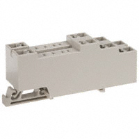
7. 封装信息:
- 尺寸:PYF14S为31 x 85x36.5 mm最大(Wx HxD),PYF08S为23.2 x 85x 36.5 mm最大(W x H x D)。
- 附件(单独订购):SOCKET BRIDGE的尺寸和颜色信息。