Type
TL-PP702
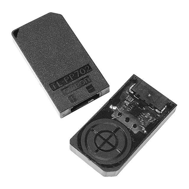
Flat Proximity Switch
Features
Two-wire DC proximity switch with built-in
connector.
4 mm in thickness.
Prevention of connector disconnection and
improvement of insertion easiness achieved
with the use of compatible positive lock
connector.
Principle of operation
An impedance change in the detection coil of the
high-frequency electronic oscillator allows a
metallic object to be detected.
Metal ball
Type
Magnetic flux
TL-PP702: Standard frequency type
Coil
Core
Specifications
Item
Detection distance (*1)
Hysteresis (*2)
Distance setting
Object to be detected
Power voltage
Leakage current (*4)
Residual voltage (*5)
Load resistance
Way of operation
Response frequency
Ambient temperature
Ambient humidity
Effect of temperature
Effect of voltage
Rating/performance
5.0 to 6.2 mm
0.2 to 2 mm
4.0 mm or less (*3)
Metal ball (Ø11 ± 0.05 mm)
12 DCV ± 10 %, 15 DCV ± 10 %, 18 DCV ± 10 %, 24 DCV ± 10 %
0.2 to 1.0 mA
Under power voltage 12 DCV: 5.4 to 7.0 V, Under power voltage 15 DCV: 5.4 to 7.0 V
Under power voltage 18 DCV: 5.4 to 7.0 V, Under power voltage 24 DCV: 5.4 to 7.0 V
Under power voltage 12 DCV ± 10%: 680 Ω (-5%) to 1.1 kΩ (+5%)
Under power voltage 15 DCV ± 10%: 1.1 kΩ (-5%) to 1.6 kΩ (+5%)
Under power voltage 18 DCV ± 10%: 1.5 kΩ (-5%) to 2.2 kΩ (+5%)
Under power voltage 24 DCV ± 10%: 2.2 kΩ (-5%) to 3.6 kΩ (+5%)
Metal ball present: Output transistor OFF
Metal ball absent: Output transistor ON
100 Hz or more
When in operation: -10 to 60 deg C (must be free from freezing or condensation)
When stored: -20 to 70 deg C (must be free from freezing or condensation)
25 to 85% RH
Within the temperature range of -10 to 60 deg C, the rate of change in the detection
range must be within ±20% relative to the range provided at 23 deg C.
Within the ±10% variation in the rated voltage, the rate of change in the detection
range must be within ±5%.
*1, 2. The detection distance and hysteresis are as shown below.
L: Hysteresis
L: Detection distance
Figure 2
Detection face
Output transistor
Detection face
Figure 1
*3. The setting must allow metal balls to pass through the space within 4 mm from the detection face of the proximity switch.
*4. Leakage current refers to the current that runs through the proximity switch when the output transistor is off.
*5. Residual Voltage refers to the voltage at both ends of the proximity switch when the output transistor is on.
1
�TL- PP702
Output circuit diagram
Operation chart
Load resistance
Proximity
switch
main
circuit
Power
supply
Metal
ball
Present
Absent
Output
transistor
* Load resistance can be connected to either + or – side.
Data of characteristics
Characteristics of leakage current [Under power voltage
18 V ± 10% and 24 V ± 10%] (Typical example)
Characteristics of leakage current [Under power voltage
12 V ± 10% and 15 V ± 10%] (Typical example)
Load resistance
Leakage current [mA]
Leakage current [mA]
Load resistance
Load resistance
Power voltage [V]
Power voltage [V]
Characteristics of residual voltage [Under power voltage
18 V ± 20% and 24 V± 10%] (Typical example)
Load resistance
Residual voltage [V]
Residual voltage [V]
Characteristics of residual voltage [Under power voltage
12 V ± 10% and 15 V± 10%] (Typical example)
Load resistance
Load resistance
Power voltage [V]
Load resistance
Load resistance
Power voltage [V]
* Load resistance refers to the load resistance shown in the above output circuit diagram.
Precautions for use
When arranging a metallic object near the proximity switch, ensure the distances greater than the ones
shown in the following figures.
(1) Along the side of case:
Iron plate of 1.0 mm in thickness
(2) Over the top or under the bottom of case:
Iron plate of 1.0 mm in thickness
* Iron plate shall be 16 mm x 30 mm.
Detection face
The switch does not malfunction when a metal ball comes into
contact with it. However, avoid using the switch with the metal
ball kept in contact with it.
2
�TL- PP702
Ensure the distances greater than the ones shown by the values in the figure below to prevent mutual
interference.
(1) Parallel arrangement
(2) Faced arrangement
150 mm: Under the combination of same
frequency switches
Detection
face
150 mm: Under the combination of same frequency switches
In the connection to an external circuit, be careful to prevent reverse connection of power supply and
short circuit of a load which cause overcurrent to flow into the proximity switch.
(1) Consecutively moving balls cannot be detected.
To detect each metal ball one by one, make the pitch of metal balls 30 mm or more.
However, the duration of operating time changes according to the location that a metal ball passes
and its speed.
The concept of the operation area for metal balls in this switch is as shown in the following figure.
(2) When detecting metal balls, avoid the method of
allowing metal balls to directly move on or fall
onto the detection face of this switch. Be sure to
use a member that prevents them from directly
contacting with the detection face.
Neglecting to do so may break the ferrite core
inside the switch due to excessive impact,
resulting in characteristic degradation and
switch malfunction.
Detection face
Detection face
Detection face
Note:
The drop height of
metal balls must be
50 mm or less.
Detection face
Detection face
Member preventing contact (T = 2.0 mm, plastic plate)
(3) If the switch is installed in a way that a metallic
object approaches the detection surface, the
metallic object itself turns on the switch or
detection distance becomes unstable. Be sure
to carefully check that these problems do not
occur.
Metallic object
Detection face
3
�TL- PP702
Exterior dimensions
Standard frequency
type: No indication
Type code
indication
Brand name
indication
Terminal symbol
indication
Lot number
indication area
Note: 1. The following shows the relationship between the
connector terminal numbers and terminal symbols.
Connector
terminal No.
Terminal
symbol
1
-
2
+
2. The housing compatible with the connector shall be
Type 502079-020* made by Molex Japan LLC.
3. The exterior dimensions shall not include the gate mark
for resin filling. The above gate mark shall be 0.3 at
maximum.
4. Lot number shall be displayed in 4 digits at the location
specified in the figure.
4
* Unless otherwise specified, the dimensional
tolerance shall be IT16. [Unit: mm]
�TL- PP70�
5
�All sales are subject to Omron Electronic Components LLC standard terms and conditions of sale, which
can be found at http://www.components.omron.com/components/web/webfiles.nsf/sales_terms.html
ALL DIMENSIONS SHOWN ARE IN MILLIMETERS.
To convert millimeters into inches, multiply by 0.03937. To convert grams into ounces, multiply by 0.03527.
OMRON ON-LINE
Global - http://www.omron.com
USA - http://www.components.omron.com
OMRON ELECTRONIC
COMPONENTS LLC
847-882-2288
Cat. No. TL-PP702(E)R03a
6
11/14
Specifications subject to change without notice
Printed in USA
�
很抱歉,暂时无法提供与“TL-PP702”相匹配的价格&库存,您可以联系我们找货
免费人工找货- 国内价格 香港价格
- 1+56.124921+7.26008
- 5+43.767985+5.66164
- 10+38.6393110+4.99822
- 30+35.2201930+4.55594
- 50+34.5313950+4.46684
- 60+34.3654260+4.44537
- 100+34.02516100+4.40135