MTA-B-03027 D (1/14)
Hardware Specifications of
V4KF-*** Series
Hybrid Manual Insertion Card Reader
Rev. A
Rev. A1
Rev. A2
Rev. A3
Rev. B
Rev. B1
Rev. B2
Rev. C
Rev. D
June 25, 2004
July 24, 2004
July 29, 2004
Nov 02, 2004
Feb 10, 2005
Feb 24, 2005
May 20, 2005
July 05, 2006
Dec 14, 2006
RoHS Compliant
©Hitachi-Omron Terminal Solutions, Corp.
All Rights Reserved.
2004-2007
�MTA-B-03027 D (2/14)
Table of Contents
Abstract
Reference Standards
Definition of Terminology
Applicable Module Name
Specifications
5.1 Mechanical Specification
5.2 Magnetic card function
5.3 ICC function
5.4
SAM
5.5
Shutter function
5.6
Lock function
5.7
Power Requirement
5.8
Electrical interface
5.9
Software interface
5.10
LED Indicator
5.11
Diagnostics function
6. Environmental Condition
7. General performance
8. Life
9.
Response to Regulated Chemical Substances
10. Outline drawing
11. Appendix A
1.
2.
3.
4.
5.
4
4
5
6
6
6
6
7
7
7
8
8
8
9
9
9
9
10
10
10
11
14
�MTA-B-03027 D (3/14)
[Specification History of Modification]
Rev
Draft
Draft2
Date
Dec 12, 2003
Feb 27, 2004
A
June 10, 2004
A1
July 24, 2004
A2
July 29, 2004
Page
ALL
Page 4, 6
Page 8
Page 9
Page 9
Page 9
Page 6
Page 7
Page 8
ALL
Page 4
Page 4
Page 7
Page 7
Content
The draft version is created.
Remove the standard ISO/IEC 7811-3
Add the signal HDRST
2
2
Correction the unit from mm/s to m/s
Correct the document number of the data transmission
specification.
Correct the low temperature from 5℃ to 0℃.
Correct the supported card type to ISO/IEC 7810/ID-1.
Correct the description of the IC function and SAM.
Correct the Pin No.10 in Power supply connector from
HDREST to NC.
Correct from ISO to ISO/IEC
Correct ISO/IEC 7810 from 1995-08-15 to 2003-11-01.
A3
B
B1
B2
Nov 02, 2004
Feb 10, 2005
Feb 25, 2005
May 20, 2005
Page 1, 7
Page 6, 7, 13
Page 11, 12
Page 6
Page 7
Page 8
Page 9
C
July 05,2006
Front page
Delete ENV1375-1: 1994
Add SLE4418 in Support ICC of Synchronous card.
Correct the standard of “Support SAM chip” in 5.4 SAM
from ENV1375 to ISO/IEC7810.
The company name is changed
Add 5SAM Version (V4KF-01JS-002).
Correction of drawing
Modify Drawing from “Mounting” to “Outline” in 5.1 [3].
Add 7.1412MHz in CLK of 5.3 [2] 4)
Add the SAM deactivation in 5.7 [5] 2).
Add the SAM in description of 5.9 [5] and 5.11
Indication of ‘RoHS Compliant’
D
Dec 14,2006
Page 10
Added Chapter 9
“Chapter No.” is changed after “Chapter 9”.
�MTA-B-03027 D (4/14)
1. Abstract
This document provides the hardware specifications of Hybrid Manual Insertion Card Reader of
V4KF-*** Series with RS232 interface. This equipment can read the data of Magnetic Card, and
read/write the data of IC card.
2. Reference Standards
[1] ISO/IEC 7810: 2003-11-01
Identification cards - Physical characteristics
[2] ISO/IEC 7811-1:2002, ISO/IEC 7811-2, 6:2001
Identification cards -- Recording technique
[3] ISO/IEC 7816-1:1998
Identification cards -- Integrated circuit(s) cards with contacts
Part 1: Physical characteristics
[4] ISO/IEC 7816-2:1999
Identification cards -- Integrated circuit(s) cards with contacts
Part 2: Dimensions and location of contacts
[5] ISO/IEC 7816-3:1997
Identification cards -- Integrated circuit(s) cards with contacts
Part 3: Electronic signals and transmission protocols
[6] ISO/IEC 7816-4: 1995
Identification cards -- Integrated circuit(s) cards with contacts
Part 4: Inter-industry commands for interchange
[7] ISO/IEC 7816-4: 1995/Amd 1:1997
Secure messaging on the structures of APDU messages
[8] EMV2000 Integrated Circuit Card Specification for Payment Systems Book 1
Application Independent ICC to Terminal Interface Requirements
Version 4.0 December, 2000
�MTA-B-03027 D (5/14)
3. Definition of Terminology
LED
Light-Emitting Diode
PCB
Printed-Circuit Board
S1
Positioning Sensor of Insertion slot
S2
Positioning Sensor of Rear End
S3
Sensor to detect the lock/release of Lock blade
ICC
Integrated Circuit Card
SAM
Secure Application Module
C/R
Card Reader
ATR
Answer to Reset
Etu
Elementary Time Unit
Vpp
Voltage at VPP
Vcc
Voltage at VCC
Host
HOST Terminal
APDU
Application Protocol Data Unit
FW
Firmware
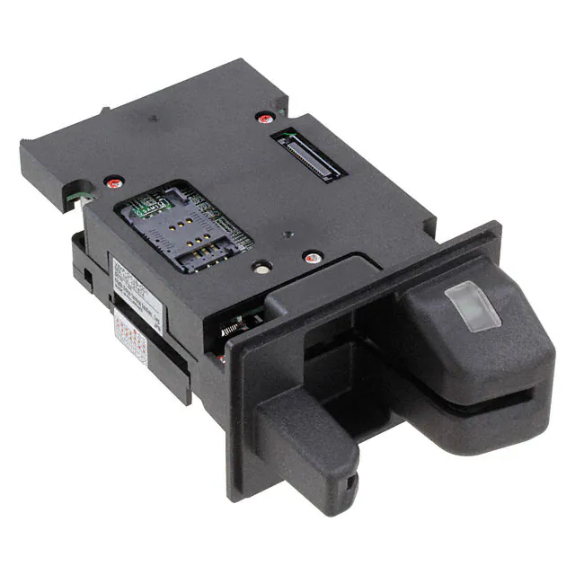
LED
Insert
PCB
ICC contact
S3
S1
LOCK
Mag. Head
S2
�MTA-B-03027 D (6/14)
4. Applicable Module Name
No
1
2
3
Module Name
V4KF-01JS-001
V4KF-01JF-001
V4KF-01JS-002
*1
*2
R
Y
Magnetic card read
Track 1 Track 2 Track 3
R*1
R
R
R
R
R
R
R
R
ICC
controller
Y*2
Y
Y
SAM
1SAM
1SAM
5SAM
Bezel
Round Type
Flat Type
Round Type
: Magnetic reading function
: 8 contacts for C1 to C8 are provided.
5. Specifications
5.1 Mechanical Specification
[1] External dimensions (See Outline Drawing)
Width
V4KF-01JS-001
80.0mm
V4KF-01JF-001
101.6mm
V4KF-01JS-002
80.0mm
*1 Including connector’s lock
Height
Length
50.0mm
76.2mm
50.0mm
133.0mm (147.0 mm *1)
133.0mm (147.0 mm *1)
134.5mm (147.0 mm *1)
[2] Weight
Less than 250g
[3] Mounting (See Outline Drawing)
(1) In case of using the Mounting Hole (V4KF-01JS-001, V4KF-01JF-001, V4KF-01JS-002)
1) Screw
M3
2) Quantity
4 pieces
3) Torque
Less than 0.79N・m
Design the mounting bases to keep the difference within +/-0.2mm in height among four
mounting holes (refer to Outline drawing about location of these holes)
(2) In case of using the Screw Hole of Bezel (V4KF-01JF-001)
1) Screw
M4
2) Quantity
4 pieces
3) Torque
Less than 1.30N・m
Select the screw in order to keep the meshing length 4.0mm or less.
[4] Card position detection
Two photo sensors (S1, S2) are provided in order to detect the card. The state of these sensors
can be retrieved by the command and response.
5.2 Magnetic card function
[1] Magnetic card type
[2] Reading function
[3] Reading direction
[4] Card speed
In conformity to ISO/IEC 7810/ID-1, ISO/IEC 7811-1/2/6
Read specified tracks simultaneously.
Bi-directional capability (insert/pull out)
100-1000 mm/s capability (at flat card)
�MTA-B-03027 D (7/14)
5.3 ICC function
[1] Number and location of contacts on ICC
Number and location of contacts on ICC are specified in ISO/IEC 7816-2 figure 2.
[2] Applicable ICC
(1) Asynchronous card
1) Support ICC
In conformity to ISO/IEC 7816-1/2/3(Default), EMV4.0 Level1
2) Protocol
T=0 and T=1
(Automatic protocol type selection via ATR detection is
possible.)
3) Data byte reading/writing
Inverse convention (MSB first, negative logic) and direct
convention (LSB first, positive logic) are available.
4) Clock during/after ATR *1
3.5712 MHz (F=372) (Default) / 7.1428 MHz (F=744)
(Conform to ISO / IEC 7816-3)
5) Communication speed
1etu = (F/D) x 1/f sec
D=1: (Default) / 2, 4: (Changeable by PPS)
6) Vpp
Not connected
7) Vcc
5V / 3V (Type A and Type B)
(Automatic selection via T=15 of ATR detection is possible.)
8) EMV Approval
EMV4.0 Level 1 Approved (11757 0504 400 20 FIM)
(2) Synchronous card
1) Support ICC
In conformity to ISO/IEC 7816-1/2/10,
SLE4442/4432/4428/4418
2) Vcc
5V
3) Vpp
Not connected
*1 Answer To Reset
HITACHI-OMRON TERMINAL SOLUTIONS asks customers to check the performance of ICC
with HITACHI-OMRON TERMINAL SOLUTIONS standard ICC controller and FW in advance, if
ICC is special card. Because ISO standard and ICC(s) are subject to frequent modification.
HITACHI-OMRON TERMINAL SOLUTIONS supports you for capability of performing customer’s
ICC, provided with ICC and its specification.
5.4 SAM
[1] The following SAM controller is equipped with shipment. 1 SAM socket is mounted on the Main PCB.
And the additional 4 SAM socket are mounted on the additional PCB in V4KF-01JS-002 only.
- 1SAM : V4KF-01JS-001, V4KF-01JF-001
- 5SAM : V4KF-01JF-002
[2] SAM specification
1) Support SAM chip
2) Protocol
3) Data byte reading/writing
4) Clock during/after ATR *1
5) Communication speed
6) Vpp
7) Vcc
In conformity to ISO/IEC 7810(ID000), ISO/IEC 7816-1/2/3
T=0 and T=1
(Automatic protocol type selection via ATR detection is
possible.)
Inverse convention (MSB first, negative logic) and direct
convention (LSB first, positive logic) are available.
3.5712 MHz(Conform to ISO / IEC 7816-3)
6
1etu = (372/D) x 1/(3.5712 x 10 ) sec
D=1: (Default) / 2, 4: (Changeable by PPS)
Not connected
5V/3V
(Automatic selection via T=15 of ATR detection is possible.)
5.5 Shutter function
[1] This shutter is equipped on the insertion slot of the C/R. It opens automatically by inserting the card. It
prevents foreign objects like dusts and coins from intruding to inside.
[2] This shutter should open by inserting the card that is more than 53.92mm in width.
�MTA-B-03027 D (8/14)
5.6 Lock function
[1] Pin type lock mechanism is equipped to hold the card during operation of ICC in response to command
from host.
[2] This lock mechanism can be controlled by the command from the host.
[3] The condition of this lock mechanism can be checked by the command and response.
[4] This lock mechanism is released automatically at the power failure.
[5] This Lock mechanism works under the below conditions
(1) The card is inserted completely.
(2) The card does not exist inside of C/R.
5.7 Power Requirement
[1] Power supply voltage
10.8 – 13.2V DC (including ripple)
[2] Ripple of power supply
100mV (p-p) or less
[3] Power consumption (Input voltage: 12V DC)
In operation
magnetic card
500mA or less
IC card
1.5A or less
In Standby
300mA or less
[4] Power supply connector
HIF3BD-10PA-254DS02 (2.54mm pitch HIROSE Japan) or equivalent (MIL-C-83503) is
mounted on C/R’s PCB.
Pin assignment of C/R (in/out direction view from the reader)
Pin No.
1
2
3
4
5
6
7
8
9
10
Assigned signal
TXD
RXD
DTR
CTS
SG
12V
GND
12V
GND
NC
IN/OUT
OUT
IN
OUT
IN
-
Function
Transmit DATA
Receive DATA
DATA Terminal Ready
Clear to Send
0V
Power
Ground
Power
Ground
Not Connect
(Cable with connector for Power supply and RS232 interface is not included)
[5] Power failure
1) Detection Voltage
Less than 10.8V DC
2) Power failure process
In case of power failure, C/R deactivates the ICC and SAM chip(s), and releases the Lock.
5.8
Electrical interface
[1] Interface specification
(1) Electronic Interface
(2) Transmission Speed
(3) Synchronous Method
(4) Communication Method
(5) Pin Assignment
RS232 interface
1200, 2400, 4800, 9600, 19200, 38400 bps
Start-Stop synchronization Method
Half-duplex Method
Refer to the table in 5.7 Power Requirement
�MTA-B-03027 D (9/14)
5.9 Software Interface
[1] Transmission protocols
[2] Port to host
[3] Format
[4] Downloadable
[5] Module
V4KF Series Card Reader Data Transmission Specification (Document
No. MTA-H-04015).
Handling with a magnetic card, an IC card and SAM via single port
A common APDU format is used for handling various ICC and SAM
All software are supported to be downloaded.
Firmware is independently divided into every functional module (e.g.
ICC handling module, SAM handling module, etc) and every module
can be independently downloaded (regardless of order of download)
respectively.
5.10 LED Indicator
[1] One LED is equipped to inform the state of C/R and the reading result of the magnetic data.
[2] This LED can be indicated the three colors (green, red and orange).
[3] The specification of LED indicator can be controlled by the command from the host. In detail, refer to
V4KF Series Card Reader Data Transmission Specification (Document No. MTA-H-04015).
5.11 Diagnostics function
[1] C/R provides the following functions as diagnostics of each module in the C/R.
This function is performed by pressing the white button located on the top of C/R just near SAM socket.
The test card is required to perform diagnostics. This function reports the following. *1
(1) OK/NG for Sensor Level
(2) OK/NG for Magnetic card reading
(3) OK/NG for LOCK mechanism
(4) OK/NG for ICC function
The SAM function is not worked.
[2] C/R indicates the result of the diagnostics by using LED indicator. *1
*1 In detail, V4KF Series Card Reader Data Transmission Specification (Document No.MTA-H-04015).
Make sure not to press this button, when the system is in operation.
6. Environmental Condition
[1] Temperature
(1) In operation
(2) In storage
[2] Humidity
(1) In operation
(2) In storage
0 to 55 ℃
-25 ℃ for 16 hours to 70 ℃ for 72 hours for non operation
and transport
5 to 85% RH, no condensation and absolute air humidity of 23
3
g/m or less
5 to 90% RH, no condensation and absolute air humidity of 40
3
g/m or less
7. General performance
[1] Insulation Resistance
[2] Dielectric Strength
[3] Durable Vibration
[4] Shock Endurance
20MΩor more at 100V DC
(At normal temperature and humidity)
500V AC for 1minute
Frequency
10-150 Hz
Single vibration width
0.10mm
2
Acceleration
15m/s
Direction
X,Y,Z
2
Acceleration
150m/s
Direction
X,Y,Z
�MTA-B-03027 D (10/14)
8. Life
[1] Card Reader life
[2] Magnetic head life *1
[3] IC contact unit life *2
800,000 passes or 5 years, whichever comes earlier.
1,000,000 passes (minimum)
300,000 operations
(Contact unit should be replaced every 300,000 operations.)
*1 One pass denotes forward and backward movement.
*2 One operation denotes the movement of fully insertion and extraction.
9. Response to Regulated Chemical Substances
[1] Response to RoHS: Conformed with RoHS Directive(2002/95/EC)
"The restriction of the use of certain hazardous substances in electrical
and electronic equipment".
(Notice) In case the equipment mounting this card reader will be shipped to People's Republic
of China,please consult our sales representatives.
�MTA-B-03027 D (11/14)
10.
Outline drawing
(1) V4KF-01JS-001
Dimensions in millimeters
�MTA-B-03027 D (12/14)
(2) V4KF-01JF-001
Dimensions in millimeters
�MTA-B-03027 D (13/14)
(3) V4KF-01JS-002
Dimensions in millimeters
�MTA-B-03027 D (14/14)
11.
Appendix A
Abstract from ISO/IEC 7816-2: 1999 (E)
4. Number and locations of the contacts
This part of ISO/IEC 7816 defines eight contacts referred to as C1 to C8.
The contacts are located as shown in figure 2.
The contacts shall be located on the front of the card. The dimensions are referenced to the left and
upper edges of the front surface of the end.
Dimensions in millimeters
Figure 2. Contacts location
�