New Product
Miniature Battery Connectors
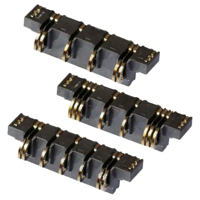
XD2B
Miniature Battery Connectors
with 13.2 mm Width and
2.6 mm Depth
• Greatly reduced board footprint with a
depth of 2.6 mm.
• Use for mid mount board, height on PCB
1.4 mm.
• Three models available for different battery
connection applications.
Model Number Legend
XD2B
(1)
(2)
(3) (4)
(1) Number of Pads
(2) Number of contact pins
(3) Pad Pitch
(4) Plating
Code
Number of Pads
Code
Pins
Code
Pitch
Code
Plating
04
4
06
6 Pins
20
2.0 mm
A
Au
05
5
07
7 Pins
23
2.3 mm
08
8 Pins
26
2.65 mm
Ratings and Characteristics
XD2B-0406-26A
Rated current *1
XD2B-0507-20A
XD2B-0408-23A
Rated voltage
2A
3A
Materials and Finish
Housing
LCP resin (UL94 V-0) / black
Contacts
Nickel alloy / nickel base, gold plated
Hold-down
Brass / nickel base, gold plated
5 VDC
1 Pin : 70 mΩ max.
Contact resistance *2
2 Pins : 35 mΩ max.
3 Pins : 35 mΩ max.
Operation durability
5000 times min.
Operating temperature
−30 to 85°C (with no condensation or icing)
*1. The rated current assumes that the end pins ( ) are used as the
power lines.
*2. The contact resistance of pins marked
is 35 mΩ. The contact
resistance of the other pins is 70 mΩ.
1
�XD2B
Ordering Information
Model
Appearance
Number of Pads
Number of
contact pins
4
6
XD2B-0406-26A
Quantity
per reel (unit) *
Battery PAD
−
(+)
+
(−)
4 PAD Type
XD2B-0507-20A
5
−
(+)
+
(−)
7
2,000
5 PAD Type
XD2B-0408-23A
4
−
(+)
+
(−)
8
4 PAD Type (High Current)
* Order in integer multiples of the quantity per reel.
Dimensions
(Unit: mm)
XD2B-0406-26A
0.5
0.9
1.4 dia.
1.4 max.
GOLD PLATING AREA
A
B
1.45±0.2 UNMATING
0.15
MATING
0.2
1.3 (Rounded end)
PICK AND PLACE SURFACE
0.4±0.05
MAXIMUM SHIFT
0.65 CONTACT POSITION
0.5
0.9±0.05
1.7±0.05
A
2.65±0.2
B
A-A
0.55
8.4±0.2
0.2±0.3
UNMATING
GOLD PLATING AREA
2 max.
9.9±0.05
13.2±0.05
0.3
0.8±0.05
1.4
PCB Mating Dimensions (TOP VIEW)
2-1.5
2.82
2-0.75±0.2
8.4±0.05
10.2±0.05
2-0.65
+0.1
0
2-1.15
+0.1
0
Reference Pad Dimensions
2-1.9
+0.1
0
2-1.4
+0.1
0
4-3.5
6-0.25
2-0.3±0.05
2-0.75
12.2
2-2.55
+0.1
0
4-0.65
)
.3
(0
2.65±0.05
2-0.7 +0.1
0
2-0.7
(Intersection with rounded part)
2-1
6-0.25
6-2.55
+0.1
0
(0.1)
1.95±0.05
+0.1
0
2-2.85
3
0.
2-1.1 +0.1
0
1.5±0.05
2-0.85 +0.1
0
R
4-
2-1.2
2-0.6
+0.1
0
+0.1
0
B-B
2-1.2
(Intersection with
rounded part)
12.2±0.05
2.65 ±0.05
8.4 ±0.05
Precautions
1. Coplanarity: 0.1 max.
2. Tolerance: ±0.1 unless otherwise specified.
2
�XD2B
XD2B-0507-20A
0.5
0.9
1.4
MAXIMUM SHIFT
GOLD PLATING AREA
0.15
MATING
1.45±0.2 UNMATING
A
B
2 max.
0.5
1.7±0.05
A
4±0.2
8.4±0.2
9.9±0.05
13.2±0.05
GOLD PLATING AREA
B
A-A
0.55
0.9±0.05
0.65 CONTACT POSITION
0.2±0.3
UNMATING
0.2
1.3 (Rounded end)
1.4 max.
.
dia
0.4±0.05
PICK AND PLACE SURFACE
0.3
0.8±0.05
1.4
2-1.5
2-1.2
(Intersection with
rounded part)
3-1
3-0.7
(Intersection with rounded part)
7-0.25
2-0.75±0.2
7-2.55
(0.1)
2-2.85 +0.1
0
2-1.1 +0.1
0
1.5±0.05
2-0.85 +0.1
0
0.3
4-R
2-1.2 +0.1
0
2-0.6 +0.1
0
1.95±0.05
+ 0.1
5-0.65 0
2.82 +0.1
0
12.2±0.05
)
.3
(0
2-0.7
3-0.65
4±0.05
+0.1
0
+0.1
0
2-1.15
B-B
Reference Pad Dimensions
2-1.9
+0.1
0
3-1.4
+0.1
0
5-3.5
7-0.25
2-0.3±0.050
2-0.75
+0.1
0
2-2.55
PCB Mating Dimensions (TOP VIEW)
12.2
4 ±0.05
8.4±0.05
8.4 ±0.05
10.2±0.05
Precautions
1. Coplanarity: 0.1 max.
2. Tolerance: ±0.1 unless otherwise specified.
XD2B-0408-23A
0.5
1.5
MAXIMUM SHIFT
1.4 dia
PICK AND PLACE SURFACE
GOLD PLATING AREA
A
B
1.45±0.2 UNMATING
0.15
MATING
1.4 max.
1.3 (Rounded end)
0.2
.
0.4±0.05
0.65 CONTACT POSITION
0.9±0.05
1
2.3±0.2
1.7±0.05
A
B
7.9±0.2
0.2±0.3
UNMATING
GOLD PLATING AREA
2 max.
A-A
0.55
9.9±0.05
13.2±0.05
2-0.7 +00.1
7.9±0.05
10.2±0.05
2-1.25 ±0.2
+0.1
0
0.3
B-B
2-0.7
(Intersection with rounded part)
2-1
8-0.25
Reference Pad Dimensions
2-1.25
8-0.25
2-2.4
+0.1
0
2-1.4
+0.1
0
2-2.55
3±0.05
2-1.65 +00.1
(0
2-0.65 +00.1
2-1.7
(Intersection with
rounded part)
8-2.55
(0.1)
3
2.82
0.
+0.1
0
R
1.95±0.05
4-
4-0.65
12.2±0.05
.3
)
2.85 +00.1
2-1.1 +0.1
0
1.5±0.05
2-0.85 +0.1
0
PCB Mating Dimensions (TOP VIEW)
2-1.2 +00.1
2-0.6 +00.1
0.8±0.05
1.4
2-2
4-3.5
2-0.3±0.05
12.2
2.3 ±0.05
7.9 ±0.05
Precautions
1. Coplanarity: 0.1 max.
2. Tolerance: ±0.1 unless otherwise specified.
3
�XD2B
Safety Precautions
Precautions for Correct Use
•For Operating
•For Mounting
(1) Do not apply excessive force to the contacts. Doing so may cause
the contacts to deform or the contact plating to peel, resulting in
contact failure.
(2) Do not touch contacts directly with your fingers or other parts of
your body. Doing so may cause the contacts to deform, resulting
in contact failure.
(1) Use reflow conditions that are within the ranges specified by
OMRON. However, reflow conditions depend on the type of
solder, manufacturer, quantity, board size, and other mounting
materials and conditions. Always confirm mounting conditions
before actual application.
(2) Do not mount the Connectors with manual soldering. If the end of
the soldering iron comes into contact with the Connector,
deformation may result.
(3) Do not perform the following operations during mounting. Doing so
may damage the Connector, resulting in contact failure or
mounting failure.
•Stack boards to which the Connectors are mounted.
•Touch the contact section or hold-downs with tweezers or other
objects.
•Apply outward force on the contact sections.
•For Designing
(1) Design the case so that the contacts are not subject to a load from
the top when the battery is inserted. Not doing so may cause the
contacts to deform, resulting in contact failure.
(2) Use the following specifications for the plating on the battery pad
surface: nickel base with gold plating of a thickness of 1.5 μm or
greater.
(3) Use a metal mask thickness of between 0.12 to 0.15 mm. The
recommended metal mask opening ratio is 90% of the processing
dimensions on the PCB in the external dimensions diagram.
(4) Design the case so that the contacts are located as shown in the
outline drawing when the battery is mated.
The contact section
Hold-down
The slit
sections
• Application examples provided in this document are for reference only. In actual applications, confirm equipment functions and safety before using the product.
• Consult your OMRON representative before using the product under conditions which are not described in the manual or applying the product to nuclear control systems, railroad
systems, aviation systems, vehicles, combustion systems, medical equipment, amusement machines, safety equipment, and other systems or equipment that may have a serious
influence on lives and property if used improperly. Make sure that the ratings and performance characteristics of the product provide a margin of safety for the system or
equipment, and be sure to provide the system or equipment with double safety mechanisms.
Note: Do not use this document to operate the Unit.
OMRON Corporation
Electronic and Mechanical Components Company
Contact: www.omron.com/ecb
Cat. No. G080-E1-03
1014(0813)(W)
�
很抱歉,暂时无法提供与“XD2B-0507-20A”相匹配的价格&库存,您可以联系我们找货
免费人工找货