XF3B
For FPC
Rotary Backlock Connector (0.3-mm Pitch, Dual-sided Contact)
Rotary Backlock Mechanism with
0.3-mm Pitch and Low Profile of 0.9 mm
• Wide molding wall on the rear bottom of the connector allows greater
freedom in board design.
• Dual-sided contact model to enhance the contact structure of lower sided.
• Gold plated with an applicable FPC thickness of 0.2 mm.
• Halogen Free (*)
* OMRON uses the following standard to determine halogen-free construction: 900 ppm
max. for Br, 900 ppm max. for Cl, and 1,500 ppm max. for Br+Cl.
RoHS compliant
■ Ratings and Specifications
Rated current
Rated voltage
Contact resistance
Insulation resistance
Dielectric strength
Insertion durability
Ambient operating temperature
■ Materials and Finish
0.2 A AC/DC
50 V AC/DC
80 mΩ max. (at 20 mV DC max., 100 mA max.)
100 MΩ min. (at 250 V DC)
250 V AC for 1 min. (leakage current: 1 mA max.)
20 times
−30 to 85 °C (With no icing or condensation)
LCP resin (UL94 V-0)/natural
LCP resin (UL94 V-0)/brown
Spring copper alloy/nickel substrate (2 μm)
Gold-plated contacts (0.15 μm)
Housing
Slider
Contacts
■ Dimensions
(Unit: mm)
XF3B-@@45-31A
XF3B-@@45-31AE
Odd number of contact
(1.4)
0.3
0.6
Recommended FPC Dimensions
Odd number
A±0.03
0.3+0.04
0.1±0.02
of contact
−0.03
A
0.12
Terminal
No.2
0.6±0.02
(0.2)
(0.2)
1.4±0.1
0.85±0.1
0.75±0.1
0.25±0.1
3.4
Odd number
of contact
(1.1) Effective
stacking length
(0.55)
Effective
stacking length
2±0.3
1.45±0.1
PCB Dimensions (TOP VIEW)
A±0.05
0.6±0.05
0.3±0.05
Terminal
No.2
Terminal
No.1
3
(Reinforcement (0.2)
board)
0.3±0.05
0.65±0.05
(4.2)
2.95±0.05
0.1
0.12
0.6
(1.4)
Even number 0.3
of contact
A
0.6
Even number ±0.02
0.6
of contact
0.12
Terminal
No.2
Terminal
1.4±0.1
No.1
0.85±0.1
0.75±0.1
0.25±0.1
Terminal
No.2
3.4
0.6
0.12
*
(0.2)
+0.04
0.3±0.02 0.3 −0.03
0.6±0.02
B±0.03
(B+0.6)±0.05
4
X
0.6±0.05
Even number
of contact
0.3+0.04
−0.03
(1.1) Effective
stacking length
(0.55)
Effective
stacking length
2±0.3
(0.3)±0.07
Pin number
indication
B
C
A±0.03
0.1±0.02
(0.2)
0.2±0.03
2-R0.2MAX
±0.07
0.3
T = 0.2 ± 0.03
(Conductive plating)
1.45±0.1
0.1
Terminal
No.1
(1.1)
(0.3)±0.07
Pin number
indication
B
C
(1.1)
0.6±0.02
B±0.03
(B+0.6)±0.05
2-R0.2MAX
0.3±0.07
3
A±0.05
0.6±0.05
0.3±0.05
Terminal
No.2
Terminal
No.1
(0.2)
0.3±0.05
0.65±0.05
(4.2)
2.95±0.05
0.6±0.05
B±0.05
0.3±0.05
1.8
*
(2.3)
0.6±0.05
0.3±0.05
0.6±0.05
0.2±0.03
Cross-section
diagram: X-X
4.5
B±0.05
XF3B
0.3+0.04
−0.03
0.3±0.02
Terminal
No.1
1.1 Effective stacking length
0.55 Effective stacking length
(2.3)
(2.1)
(1.6)
0.9
Reference
pin mark
*
X
0.35
D
FPC insertion dimension
Table of Dimensions
Pins*1
8
19
25
Model
XF3B-0845-31A
XF3B-1945-31A
XF3B-2545-31A
A
1.8
4.8
6.6
B
2.1
5.4
7.2
3.8
C
D
4.3 2.75
7.6 6.05
9.4 7.85
0.4
* Dotted lines indicate the shape and dimensions
of the XF3B-@@45-31AE connectors.
Pins*1
35
51
67
Model
XF3B-3545-31A
XF3B-5145-31AE
XF3B-6745-31AE
A
B
C
D
9.6 10.2 12.4 10.85
14.4 15.0 17.2 15.65
19.2 19.8 22.0 20.45
■ Ordering Information
Pins*1
8
19
25
35
Model
XF3B-0845-31A
XF3B-1945-31A
XF3B-2545-31A
XF3B-3545-31A
Quantity per reel (unit)*2
2,000
Pins*1
Model
Quantity per reel (unit)*2
51
XF3B-5145-31AE
1,500
67
XF3B-6745-31AE
*1. Please consult your OMRON representative for available pin count.
*2. Please order by integer multiple of the quantity per reel.
7
�
很抱歉,暂时无法提供与“XF3B-6745-31AE”相匹配的价格&库存,您可以联系我们找货
免费人工找货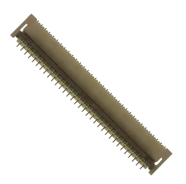


 工商网监
湘ICP备2023018690号
工商网监
湘ICP备2023018690号
