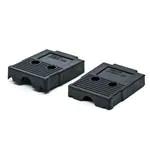
D-sub Connectors
XM3/XM2S
The D-sub Connector are Ideal for Office
Automation Interfacing
• Shielded against EMI.
• Multi-hole, ferrite-core Connectors (XM3B-F) offers space-saving design and superior noise protection at high frequency.
• Rugged, compact, metallized plastic hood (XM2S) provides
excellent noise protection.
• Conforms to UL standards. (No. E103202)
(XM2S hoods and other models not included.)
• Available with many kinds of standard Anchors and grounding fixtures.
• RoHS Compliant.
Connectors and Hoods
Model
Type
XM3B
XM3B-F
Sockets with Right-angle
DIP Terminals
Sockets with Right-angle
DIP Terminals and ferrite core
Appearance
Model
Type
XM3C
XM3F
XM3A
XM3D
Plugs with Right-angle
DIP Terminals
Sockets with Straight
DIP Terminals
Plugs with Solder Cup
Terminals
Sockets with Solder Cup
Terminals
Appearance
Model
XM2S
XM2S-E
Right Angle Cable Connection
Straight Cable Connection,
Type Straight Cable Connection
Metallized Plastic for 9 and 25 terminal models with ESD Production for 9 terminal models
Metallized Plastic
Appearance
D-sub Connectors
XM3/XM2S
1
�■ Ratings and Characteristics
XM3A, XM3B, XM3B-F,
XM3C (except 37 terminal models),
XM3D, XM3F
Rated current
5A
Rated voltage
300 VAC
Contact resistance
15 mΩ max. (at 20 mV, 100 mA max.)
XM3C - 37 terminal models
XM2S, XM2S-E
(Hoods)
3A
Insulation resistance
1,000 MΩ min. (at 500 VDC)
Dielectric strength
1,000 VAC for 1 min. (leakage current: 1 mA max.)
Total insertion force
Number of terminals x 3.33 N max.
Removal force
0.29 N min. (for gauge diameter of 0.99 mm)
Insertion Durability
200 times
Ambient operating
temperature
−55°C to 105°C (with no icing)
Shield performance
Mounted in panel: 25 dB min. (30 to 900 MHz)
Mounted on board: 20 dB min. (30 to 900 MHz)
---
−25°C to 85°C
---
■ Materials and Finish
Connectors
XM3B
Housing
XM3B-F
XM3C
XM3F
XM3A
Fiber-glass reinforced PBT resin (UL94V-0)/black
Contacts Mating End Phosphor Bronze / Nickel base, gold plated (0.4 μm)
Terminals
Shell
Phosphor Bronze / Nickel base,
tin plated (2 μm)
XM3D
Fiber-glass reinforced PBT resin
(UL94V-0)/Milky white
Bronze / Nickel Phosphor
base, gold plated Bronze / Nickel
(0.4 μm)
base, gold plated
(0.4 μm)
Phosphor Bronze / Nickel base,
tin plated (3 μm)
Bronze / Nickel Phosphor
base, tin plated Bronze / Nickel
(3 μm)
base, tin plated
(3 μm)
Steel.
Nickel plated
Hoods
XM2S
Straight Connecting Cable
Housing
XM2S-E
Right-angle Connecting Cable
ABS resin / nickel plated
Cable clamp
Straight Connecting Cable with
ESD Protection
ABS resin
Steel / nickel plated
Lock screw (Driver type)
Steel / nickel plated
---
---
Lock screw (Jackscrew)
Brass / nickel plated (See note)
Brass / nickel plated
Fiber-glass reinforced polyamide
(UL94V-0)/black
Note: Jackscrews (thumbscrews) for the straight, non-ESD version of the XM2S hood are sold separately. See “Accessories” section of this datasheet.
■ Applicable Wires
The applicable wires for solder cup terminals are AWG 22 to 28 (solid or stranded).
2
D-sub Connectors
XM3/XM2S
�XM3B Sockets with Right-angle DIP Terminals
Dimensions
(unit:mm)
XM3B-@@22-@@@
Two, 3.1 dia.
25-contact model shown above.
(With anchor 2, Lock Pin, Grounding Fixtures)
Mounting holes (t = 1.6 mm, bottom view)
No. of
contacts
Two, 3.2 ±0.1 dia.
1 ±0.1 dia.
A
B
C
D
E
F
9
30.8
24.99
16.30
10.96
8.22
2.74
15
39.1
33.32
24.65
19.18
16.44
2.74
25
53.0
47.04
38.35
33.12
30.36
2.76
37
69.3
63.50
54.80
49.68
46.92
2.76
Note: XM3B Sockets were manufactured in accordance with JIS X 5101. Terminal pitches are a mixed arrangement
of 2.77 and 2.74 mm contacts on 25 and 37 contact models as specified in the JIS standard. A pitch of 2.76 mm
is recommended for the mounting holes because of the more advanced numerical control available today.
This is sufficient to avoid any problems.
Ordering Information
Anchor 2
Anchor 2
Appearance
Lock Pin Grounding
Fixture
Tap Hole Grounding
Fixture
Accessories
No. of
contacts
XM2Z-0011 Anchor 2
(M2.6 × 0.45 metric screws)
XM2Z-0013 Anchor 2
(#4-40 UNC inch screws)
XM2Z-0011 Anchor 2 (M2.6 × 0.45 XM2Z-0013 Anchor 2 (#4-40 UNC
metric screws)
inch screws)
XM2Z-0061
Tap Hole Grounding Fixtures
XM2Z-0062
Lock Pin Grounding Fixtures
9
XM3B-0922-111
XM3B-0922-131
XM3B-0922-112
XM3B-0922-132
15
XM3B-1522-111
XM3B-1522-131
XM3B-1522-112
XM3B-1522-132
25
XM3B-2522-111
XM3B-2522-131
XM3B-2522-112
XM3B-2522-132
37
XM3B-3722-111
XM3B-3722-131
XM3B-3722-112
XM3B-3722-132
Appearance
Tap Hole Grounding
Fixture
Accessories
Lock Pin Grounding
Fixture
No anchors
No. of
contacts
---
XM2Z-0061
Tap Hole Grounding Fixtures
XM2Z-0062
Lock Pin Grounding Fixtures
9
XM3B-0922
XM3B-0922-501
XM3B-0922-502
15
XM3B-1522
XM3B-1522-501
XM3B-1522-502
25
XM3B-2522
XM3B-2522-501
XM3B-2522-502
37
XM3B-3722
XM3B-3722-501
XM3B-3722-502
Note: 1. Use the XM3B-@@22 (No anchors or grounding fixtures) in combination with suitable Anchors and Grounding Fixtures.
2. Two M3 x 0.5 Tap Hole Grounding Fixtures and an M3 x 0.5 Lock Pin Grounding Fixture for the Anchor Side are provided.
D-sub Connectors
XM3/XM2S
3
�XM3B-F Sockets with Right-angle DIP Terminals and Ferrite Cores
Dimensions
(unit:mm)
XM3B-@@22-501F
25-contact model shown above.
(With Tap Hole Grounding Fixtures)
Two, M3
Tap Hole Grounding
Fixture
Two, M3
Ferrite core
Mounting holes (t = 1.6 mm, bottom view)
No. of
contacts
Two, 3.2 ±0.1 dia.
A
B
C
D
E
F
G
9
30.8
24.99
16.30
10.96
8.22
2.74
14.3
15
39.1
33.32
24.65
19.18
16.44
2.74
22.0
25
53.0
47.04
38.35
33.12
30.36
2.76
36.5
37
69.3
63.50
54.80
49.68
46.92
2.76
53.3
1 ±0.1 dia.
Note: XM3B Sockets were manufactured in accordance with JIS X 5101. Terminal pitches are a mixed arrangement
of 2.77 and 2.74 mm contacts on 25 and 37 contact models as specified in the JIS standard. A pitch of 2.76 mm
is recommended for the mounting holes because of the more advanced numerical control available today.
This is sufficient to avoid any problems.
Ordering Information
Appearance
Tap Hole Grounding Fixture
Accessories
XM2Z-0061
Tap Hole Grounding Fixtures
No. of
contacts
9
XM3B-0922-501F
15
XM3B-1522-501F
25
XM3B-2522-501F
37
XM3B-3722-501F
4
D-sub Connectors
XM3/XM2S
�XM3C Plugs with Right-angle DIP Terminals
Dimensions
XM3C-@@22-@@@
(unit:mm)
A
B
C
D
E
F
G
3.2
6.25
25-contact model shown above.
(No Anchor or Grounding Fixtures)
12.5
N
N-1
8.35
2
1
Two, 3.1 dia.
5.9
0.3
Mounting holes (t = 1.6 mm, bottom view)
B±0.1
18.5
D±0.1
3.6
2.84
9.6
E±0.1
F±0.1
3.3
3.0
B
No. of
contacts
15.5
9.9
N-1 N
1 2
3.0
1±0.1 dia.
2.84±0.1
Two, 3.2±0.1 dia.
F±0.1
A
B
C
D
E
F
G
9
30.8
24.99
16.91
10.96
8.22
2.74
1.37
15
39.1
33.32
25.25
19.18
16.44
2.74
1.37
25
53.0
47.04
38.96
33.12
30.36
2.76
1.38
37
69.3
63.50
55.42
49.68
46.92
2.76
1.38
Note: XM3C Sockets were manufactured in accordance with JIS X 5101. Terminal pitches are a mixed arrangement of 2.77 and 2.74 mm contacts on 25 and 37 contact models as specified in the JIS standard. A pitch of 2.76 mm is recommended for the mounting holes because
of the more advanced numerical control available today. This is sufficient to avoid any problems.
Ordering Information
Tap Hole Grounding Fixture
Lock Pin Grounding Fixture
Appearance
Anchor 2
Anchor 2
XM2Z-0011 Anchor 2
(M2.6 × 0.45 metric screws)
Accessories
No. of
contacts
Tap Hole Grounding Fixtures
Lock Pin Grounding Fixtures
9
XM3C-0922-111
XM3C-0922-112
15
XM3C-1522-111
XM3C-1522-112
25
XM3C-2522-111
XM3C-2522-112
37
XM3C-3722-111
XM3C-3722-112
Tap Hole Grounding Fixture
Lock Pin Grounding Fixture
Appearance
Accessories
No anchors
No. of
contacts
---
Tap Hole Grounding Fixtures
Lock Pin Grounding Fixtures
9
XM3C-0922
XM3C-0922-501
XM3C-0922-502
15
XM3C-1522
XM3C-1522-501
XM3C-1522-502
25
XM3C-2522
XM3C-2522-501
XM3C-2522-502
37
XM3C-3722
XM3C-3722-501
XM3C-3722-502
Note: 1. Use the XM3C-@@22 (No anchors or grounding fixtures) in combination with suitable Anchors and Grounding Fixtures.
2. Two M3 x 0.5 Tap Hole Grounding Fixtures and an M3 x 0.5 Lock Pin Grounding Fixture for the Anchor Side are provided.
3. XM3C-@@22-@3@ versions with Inch Screws are also available.
D-sub Connectors
XM3/XM2S
5
�XM3F Sockets with Straight DIP Terminals
Dimensions
XM3F-@@20
(unit:mm)
XM3F-@@20-112
25-contact model shown on the left.
(No anchors or grounding fixtures)
25-contact model shown on the left.
(With Anchors and Grounding Fixtures)
A
A
Two, 3.1 dia.
B
N-1
N
N-1
12.5 7.9
12.5 7.9
1
M2.6×0.45
B
1
H
2
H
5
6.1
0.3
6.8
7
0.5
7
0.7
3.2
0.5
3.2
6.1
N
6
2
0.3
Anchor
2.8
0.7
2.84
C
C
F
F
1
Lock Pin
Grounding 0.5
Fixture
1
2
2
9
9
N-1
D
N
N-1
D
E
G
N
E
G
Mounting holes (t = 1.6 mm, bottom view)
B±0.1
No. of
contacts
A
B
C
D
E
F
G
E±0.1
H
9
30.7
24.99
10.98
1.37
8.22
2.74
19.00
16.33
15
39.0
33.32
19.20
1.37
16.44
2.74
27.12
24.66
25
52.9
47.04
33.12
1.38
30.36
2.76
41.04
38.38
37
69.2
63.50
49.68
1.38
46.92
2.76
57.60
54.84
(D)
Two, 3.2±0.1 dia.
F±0.1
N N-1
2
F±0.1
1±0.1 dia.
C±0.1
Ordering Information
Appearance
No. of
contacts
No anchors or Grounding Fixtures
Anchors and Lock Pin Grounding Fixtures
9
XM3F-0920
XM3F-0920-112
15
XM3F-1520
XM3F-1520-112
25
XM3F-2520
XM3F-2520-112
37
XM3F-3720
XM3F-3720-112
D-sub Connectors
XM3/XM2S
1
2.84
2.84
�XM3A Plugs with Solder-cup Terminals
XM3D Sockets with Solder-cup Terminals
Dimensions
XM3A-@@21
(unit:mm)
A
B
C
D
Two, 3.1 dia.
E
1
2
12.4 8.35
N-1 N
G
F
Note: 25-contact model shown above.
5.9
8.25
1.5
1.48 dia.
No. of
contacts
A
B
C
D
E
F
G
9
30.7
24.99
16.91
10.96
8.22
2.74
1.37
15
39.0
33.32
25.25
19.18
16.44
2.74
1.37
25
52.9
47.04
38.96
33.12
30.36
2.76
1.38
37
69.2
63.50
55.42
49.68
46.92
2.76
1.38
E
F
G
XM3D-@@21
A
B
C
D
E
Two, 3.1 dia.
2
1
12.4 7.9
N
G
N-1
F
Note: 25-contact model shown above.
6.1
8.45
1.5
No. of
contacts
1.53 dia.
A
B
C
D
9
30.7
24.99
16.33
10.96
8.22
2.74
1.37
15
39.0
33.32
24.66
19.18
16.44
2.74
1.37
25
52.9
47.04
38.38
33.12
30.36
2.76
1.38
37
69.2
63.50
54.84
49.68
46.92
2.76
1.38
Ordering Information
Plugs
Sockets
Appearance
No. of
contacts
9
XM3A-0921
XM3D-0921
15
XM3A-1521
XM3D-1521
25
XM3A-2521
XM3D-2521
37
XM3A-3721
XM3D-3721
D-sub Connectors
XM3/XM2S
7
�XM2S / XM2S-E Straight and Right Angle Hoods
Dimensions
(unit:mm)
9-contact Hood
with Straight Connecting Cable
XM2S-091@
9-contact Hood
15, 25 and 37-Contact Hoods
Max. applicable diameter: 9 dia.
Max. applicable cable diameter: F dia.
Dot (screw head)
15, 25 and 37-contact Hood
with Straight Connecting Cable
XM2S-@@1@
Lock screw
M2.6 × 0.45
M3 × 0.5
#4-40 UNC
Lock screw
M2.6 × 0.45
M3 × 0.5
#4-40 UNC
No. of
contacts
Dot Shape
No dot
1 dot
2 dots
A
B
C
D
E
F
15
40.5
33.32
26.5
19
30
10
25
54.0
47.04
40
29
38
11
37
70.5
63.50
57
42
50
13
(unit:mm)
9-contact Hood with
Right-angle Connecting Cable
XM2S-092@
16
5 dia.
48
5.5
25.2
Groove
Max. applicable
cable diameter: 9 dia.
18.2
24.99
45
25-contact Hood with
Right-angle Connecting Cable
XM2S-252@
Lock screw
M2.6 × 0.45
15
Max. applicable diameter: 11 dia. (See note.)
Note: The maximum applicable cable diameter for
the 25-contact right-angle hood is 9 dia if
the cable clamp supplied is mounted facing
the rear.
Do not use a cable bushing in this case.
5 dia.
23
41
39
6
Lock screw
M2.6 × 0.45
M3 × 0.5
#4-40 UNC
Groove Shape
No Groove
1 Groove
2 Grooves
Groove
40
47.04
54
8
D-sub Connectors
XM3/XM2S
�(unit:mm)
Max. applicable cable diameter: 9 dia.
9-contact Hood
with Straight Connecting Cable
and ESD Protection
XM2S-0911-E
15
11
13
40.8
18.2
24.99
32.2
M2.6 × 0.45
Note: Jackscrews (thumbscrews) for the straight, non-ESD version of the XM2S hood are sold separately. See “Accessories” section of this datasheet.
Ordering Information
Straight hoods
M2.6 x 0.45 metric screws
(No dot)
M3 x 0.5 metric screws
(1 dot)
#4-40 UNC inch screws
(2 dots)
Anchor 1
XM2Z-0001
XM2Z-0002
XM2Z-0003
Anchor 2
XM2Z-0011
XM2Z-0012
XM2Z-0013
Anchor 3
XM2Z-0021
XM2Z-0022
XM2Z-0023
Lock screw
Applicable
Anchors
No. of contacts
9
XM2S-0911
XM2S-0912
XM2S-0913
15
XM2S-1511
XM2S-1512
XM2S-1513
25
XM2S-2511
XM2S-2512
XM2S-2513
37
XM2S-3711
XM2S-3712
XM2S-3713
*Jackscrews(thumbscrews) for the straight hoods without ESD protection are sold separately. See XM2Z-007@ (Anchor 5) in the Accessories section of this datasheet.
Right-angle hoods
M2.6 x 0.45 metric screws
(No groove)
M3 x 0.5 metric screws
(1 groove)
#4-40 UNC inch screws
(2 groove)
Anchor 1
(See Note 3)
XM2Z-0001
XM2Z-0002
XM2Z-0003
Anchor 2
XM2Z-0011
XM2Z-0012
XM2Z-0013
Anchor 3
XM2Z-0021
XM2Z-0022
Lock screw
Applicable
Anchors
No. of contacts
XM2Z-0023
9
XM2S-0921
XM2S-0922
XM2S-0923
25
XM2S-2521
XM2S-2522
XM2S-2523
*Jackscrews (thumbscrews) for the right-angle hoods are standard, supplied with the hoods.
Straight hood with ESD Protection
Lock screw
Applicable
Anchors
No. of contacts
9
M2.6 x 0.45 metric screws
(No groove)
Anchor 1
XM2Z-0001
Anchor 2
XM2Z-0011
Anchor 3
XM2Z-0021
XM2S-0911-E
*Overmolded Jackscrews (thumbscrews) for the straight hoods with ESD protection are standard, supplied with the hoods.
Note: 1. The cable bushing, cable clamp, shielded tape and assorted screws are supplied with all hoods
2. Lock screws are attached to the Hood. Select D-sub Connectors with Anchors or Grounding Fixtures that fit the lock screw of the hood.
3. Anchor 1 cannot be used with the 9 Contact Right-angle Hoods.
D-sub Connectors
XM3/XM2S
9
�Accessories for XM3 (Sold Separately)
■ XM2T Dust Covers for Sockets
With Retaining Ring
XM2T-@@01
Dust Cover holding ring
0.9 dia.
No. of
contacts
A
B
C
D
Model
9
17.7
16.3
8
68
XM2T-0901
15
26.1
24.7
10
77
XM2T-1501
25
39.8
38.4
15
120
XM2T-2501
37
56.2
54.8
18
135
XM2T-3701
Without Retaining Ring
XM2T-@@01-0
XM2T Rating and Material
Operating Temperature
−25°C to 85°C
Material
Polyamide resin
No. of
contacts
A
B
C
Model
9
17.7
16.3
8
XM2T-0901-0
15
26.1
24.7
10
XM2T-1501-0
25
39.8
38.4
15
XM2T-2501-0
37
56.2
54.8
18
XM2T-3701-0
■ XM2Z Anchors
Anchor 1 (Rectangular)
XM2Z-000@
Thread Type
Anchor 2 (Hexagonal)
XM2Z-001@
Model
M2.6 x 0.45 metric screw XM2Z-0001
M3 x 0.5 metric screws
XM2Z-0002
#4-40 UNC inch screws
XM2Z-0003
Thread Type
Materials and Finish
Zinc die-cast/nickel plated
Anchor 3 (Hexagonal)
XM2Z-002@
Model
Thread Type
Model
M2.6 x 0.45 metric screw XM2Z-0011
M2.6 x 0.45 metric screw XM2Z-0021
M3 x 0.5 metric screws
XM2Z-0012
M3 x 0.5 metric screws
XM2Z-0022
#4-40 UNC inch screws
XM2Z-0013
#4-40 UNC inch screws
XM2Z-0023
Materials and Finish
Iron/nickel plated
Materials and Finish
Iron/nickel plated
5
5
Part A
Female screw
(Mates with lock screw)
Female screw
(Mates with lock
screw and
mounting screw)
Female screw
(mates with lock screw)
M3 × 0.5
M2.6 × 0.45
M3 × 0.5
#4-40 UNC
Note: When using a Dust Cover, secure the
holding ring at part A.
Note: 2 anchors are necessary per connector. Anchors are not packaged in pairs.
10
M3 × 0.5
D-sub Connectors
XM3/XM2S
Note: Anchor 3 is used for panel mounting
connectors. Applicable cable panel
thickness is 0.6 to 1.3 mm.
�Anchor 5
XM2Z-007@
Thread Type (A)
Number of
Grooves
Screw A
2.35 dia.
Groove Shape
Model
M2.6 x 0.45 metric screw None
XM2Z-0071
M3 x 0.5 metric screws
1
XM2Z-0072
#4-40 UNC inch screws
2
XM2Z-0073
4 dia.
Materials and Finish
Brass/nickel plated
Note: Anchor 5 is for use only with the Straight Connecting XM2S hoods, to provide a Thumbscrew feature.
2 anchors are necessary per connector. Anchors are not packaged in pairs.
■ XM2Z Grounding Fixtures for XM3B
Tap Hole Grounding Fixtures
XM2Z-006@
Lock Pin Grounding Fixtures
XM2Z-006@
Material and Finish
Steel/nickel plated
Material and Finish
Phosphor bronze/nickel plated
Applicable through-hole diameter: 3.2 dia.
Fixed side tap hole
(M3 × 0.5) or through
hole (3.5 dia.)
Fixed side tap hole
(M3 × 0.5) or through
hole (4.0 dia.)
PCB side
M3 × 0.5
Tap Hole
Grounding Fixtures
Thread Type
Lock Pin
Grounding Fixtures
Fixed-side tap holes
XM2Z-0061
XM2Z-0062
Fixed-side through holes
XM2Z-0063
XM2Z-0064
Note: 2 Grounding Fixtures are necessary per connector. Grounding Fixtures are not packaged in pairs.
Assembly Information
■ Anchors and Grounding Fixtures
Anchor 2 and 3
Anchor 1
Connector
Anchor
2 or 3
Grounding Fixture
(fixed-side tap hole)
Anchor 1
Without Anchor
Connector
Grounding
Fixture (fixedside tap hole)
Commercial
screws
Commercial
screws (M3)
Connector
Commercial
hexagonal
nut (M3)
Note: Always use a screw without an Anchor.
Note: 1. Use Grounding Fixtures
A grounding Fixture (fixed-side tap) can
XM2Z-0063 or XM2Z-0064.
be used in place of the hexagonal nut.
2. Use a 6-mm screw that mates with the male
screw on Anchor 1.
Note: Use Grounding Fixtures
XM2Z-0061 or XM2Z-0062.
■ Combination of Hexagonal Anchors for each connector (in post installation)
Type
DIP L type socket
Model
XM3B-@@22
Without Panel Insertion
XM2Z-001@
With Panel Insertion
XM2Z-002@
XM3B-@@22-501@
Commercially available nut
Necessary
Not Necessary
XM3B-@@22-502
DIP L type plug
XM3C-@@22
XM2Z-001@
XM2Z-002@
XM3C-@@22-501
Necessary
Not Necessary
XM3C-@@22-502
DIP straight socket
XM3F-@@20
XM2Z-001@
XM2Z-002@
D-sub Connectors
Necessary
XM3/XM2S
11
�■ Combination Examples
Relaying Example
Hood
Hood
Anchor 1
Hood
(XM2S-@@1@)
Lock screw M2.6 × 0.45
(See note.)
Anchor 1
Plug
Note: Screw the lock screw of the Hood into the hole on Anchor 1.
Plug with Solder-cup Terminals
Sockets and Right-angle DIP
Terminals (With Anchor 2 and
Lock Pin Grounding Fixtures)
Sockets and Right-angle DIP
Terminals (no anchor or
grounding fixtures)
Sockets with Solder-cup Terminals
Panel-mounting Sockets
Anchor
Sockets
Sockets with Right-angle DIP
Terminals (With Anchor 2 and
Tap Hole Grounding Fixtures)
Anchor 2
(XM2Z-001@)
Anchor 1
(XM2Z-000@)
Panel
Commercial
nut
Connector
Commercial
M3 nut
Commercial
screw
Anchor 2
Anchor 3
Connector
Anchor 3
Anchor 1
Panel
(t = 1.3 max.)
XM3D
Not secured to the panel
Anchor 2
Applicable anchors
6.4 min.
Two, R3.2
No. of contacts
9
15
25
37
13 min.
11.4 min.
Four, R1
Four, R2.5
A (mm)
31.0
39.4
53.3
69.6
No. of contacts
9
15
25
37
Note: 1. 2 Anchors are required per connector. Anchors are not packaged in pairs
2. Applicable panel thickness is 1.3 mm max.
D-sub Connectors
Two, 3.2
±0.1 dia.
A min.
11.4 min.
Panel
dimensions
Secured to the panel
Anchor 3 or M3 screws
Anchor 1
A min.
Panel Dimensions
Commercial
M3 nut
Connector
Panel mounting procedure
12
Panel
(t = 1.3 max.)
Panel
Anchor 3
(XM2Z-002@)
XM3/XM2S
A (mm)
34.1
42.4
56.1
72.6
Four, R3.4
No. of contacts A (mm)
9
15
25
37
24.99
33.32
47.04
63.50
B (mm)
20.5
28.8
42.5
59.1
�Precautions
■ Correct Use
Grounding
Shielded Cable Preparation
To ground, create copper foil around the connector attachment hole on the
board, assemble the connector and grounding fixture, and dip in solder as
shown below.
Refer to the following diagram when soldering shielded cable to the connector
when using a hood.
No. of Contacts
Tap Hole Grounding Fixtures
Insert the connector into the PCB, tighten the screws, and then dip-solder the
connector terminals to the board.
L (mm)
9
25
15
35
25
40
37
45
Tap Hole Grounding Fixtures
Braided shield
Cable bushing
PCB (t = 1.6 mm)
Approx. 2.3
10 ±1 (Folded shield dimensions)
12 (Taped shield dimensions)
M3 screw
Lock Pin Grounding Fixtures
Insert the connector into the PCB and then simultaneously dip-solder the connector terminals and lock pin to the board.
Lock Pin Grounding Fixtures
1. Fold the unravelled braided shield back over the cable bushing
2. Wrap tape around the folded shield.
Shield Effects
When connecting the braided cable shield to a connector hood, use the cable
clamp to clamp all the braids at once through the shielded tape.
Mate the lock screw washer and spring washer outside the connector when
assembling the hood.
PCB (t = 1.6 mm)
Clamp screws (2)
Cable bushing (1)
Shielded tape (1)
Approx.
2.2 to 2.5
Cable clamp
Lock screw
washers (2)
with spring
washer
Attaching the Dust Cover
Cover screw
hexagonal nut
(2)
To attach the cord to the connector, use Anchor 1 and secure it as shown
below.
Cord
XM3B
Anchor 1
To attach the cord to a panel, drill an M3 hole in the panel and secure the cord
to it with an M3 screw. If the cord is not required, cut it off. Use a commercially
available M3 screw.
Keep the shell flange of the connector as far away from the metal panel as
possible to maximize the shield effect with a connector mounted to a panel.
The ground wire for the connector will fall into the shell (external metal covering) with solder-cup terminals, so connect the ground wire to the panel or to
ground on the board.
Shell flange
Gap
Panel mounting holes
Panel
XM3A/XM3D Connector Insertion and Removal
Grasp the connector or the hood cover when inserting and removing the connector. Never try to remove the connector by pulling the cable.
Tightening Clamp Screws
Use the following torques when tightening cable clamp to hood.
Terminal Screw Tightening Torque (N·m)
9
Contacts
15
Contacts
0.25
0.44
25
Contacts
37
Contacts
Soldering - Automated Soldering Conditions.
(Jet Flow) (XM3B, XM3C and XM3F)
1. Soldering temperature: 250 ±5°C
2. Continuous soldering time: Within 5 s
0.49
D-sub Connectors
XM3/XM2S
13
�All sales are subject to Omron Electronic Components LLC standard terms and conditions of sale, which
can be found at http://www.components.omron.com/components/web/webfiles.nsf/sales_terms.html
ALL DIMENSIONS SHOWN ARE IN MILLIMETERS.
To convert millimeters into inches, multiply by 0.03937. To convert grams into ounces, multiply by 0.03527.
OMRON ON-LINE
OMRON ELECTRONIC
COMPONENTS LLC
Global - http://www.omron.com
USA - http://www.components.omron.com
55 E. Commerce Drive, Suite B
Schaumburg, IL 60173
847-882-2288
Cat. No. G057-E-1a
14
D-sub Connectors
01/13
Specifications subject to change without notice
XM3/XM2S
Printed in USA
�