2N5190G, 2N5191G,
2N5192G
Silicon NPN Power
Transistors
Silicon NPN power transistors are for use in power amplifier and
switching circuits − excellent safe area limits. Complement to PNP
2N5194, 2N5195.
http://onsemi.com
4.0 AMPERES
NPN SILICON
POWER TRANSISTORS
40, 60, 80 VOLTS − 40 WATTS
Features
• Epoxy Meets UL 94 V−0 @ 0.125 in.
• These Devices are Pb−Free and are RoHS Compliant*
MAXIMUM RATINGS
Rating
Symbol
Value
Unit
Collector−Emitter Voltage
2N5190G
2N5191G
2N5192G
VCEO
Collector−Base Voltage
2N5190G
2N5191G
2N5192G
VCBO
Emitter−Base Voltage
VEBO
5.0
Vdc
Collector Current
IC
4.0
Adc
Base Current
IB
1.0
Adc
Total Device Dissipation
@ TC = 25°C
Derate above 25°C
PD
40
320
W
mW/°C
TJ, Tstg
–65 to +150
°C
ESD − Human Body Model
HBM
3B
V
ESD − Machine Model
MM
C
V
Operating and Storage Junction
Temperature Range
COLLECTOR
2, 4
Vdc
40
60
80
3
BASE
1
EMITTER
Vdc
40
60
80
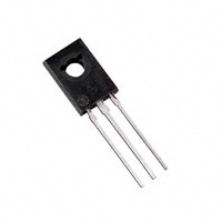
TO−225
CASE 77−09
STYLE 1
1 2
3
MARKING DIAGRAM
YWW
2
N519xG
Stresses exceeding those listed in the Maximum Ratings table may damage the
device. If any of these limits are exceeded, device functionality should not be
assumed, damage may occur and reliability may be affected.
THERMAL CHARACTERISTICS
Characteristic
Symbol
Max
Unit
Thermal Resistance, Junction−to−Case
RqJC
3.12
°C/W
Y
= Year
WW
= Work Week
2N519x = Device Code
x = 0, 1, or 2
G
= Pb−Free Package
ORDERING INFORMATION
Device
*For additional information on our Pb−Free strategy and soldering details, please
download the ON Semiconductor Soldering and Mounting Techniques
Reference Manual, SOLDERRM/D.
© Semiconductor Components Industries, LLC, 2013
December, 2013 − Rev. 15
1
Package
Shipping
2N5190G
TO−225
(Pb−Free)
500 Units/Box
2N5191G
TO−225
(Pb−Free)
500 Units/Box
2N5192G
TO−225
(Pb−Free)
500 Units/Box
Publication Order Number:
2N5191/D
�2N5190G, 2N5191G, 2N5192G
ELECTRICAL CHARACTERISTICS* (TC = 25_C unless otherwise noted)
Symbol
Characteristic
Min
Max
Unit
OFF CHARACTERISTICS
VCEO(sus)
Collector−Emitter Sustaining Voltage (Note 1)
(IC = 0.1 Adc, IB = 0)
2N5190G
2N5191G
2N5192G
Vdc
40
60
80
Collector Cutoff Current
(VCE = 40 Vdc, IB = 0)
2N5190G
(VCE = 60 Vdc, IB = 0)
2N5191G
(VCE = 80 Vdc, IB = 0)
2N5192G
ICEO
Collector Cutoff Current
(VCE = 40 Vdc, VEB(off) = 1.5 Vdc)
2N5190G
(VCE = 60 Vdc, VEB(off) = 1.5 Vdc)
2N5191G
(VCE = 80 Vdc, VEB(off) = 1.5 Vdc)
2N5192G
(VCE = 40 Vdc, VEB(off) = 1.5 Vdc, TC = 125_C)
2N5190G
(VCE = 60 Vdc, VEB(off) = 1.5 Vdc, TC = 125_C)
2N5191G
(VCE = 80 Vdc, VEB(off) = 1.5 Vdc, TC = 125_C)
2N5192G
ICEX
Collector Cutoff Current
(VCB = 40 Vdc, IE = 0)
2N5190G
(VCB = 60 Vdc, IE = 0)
2N5191G
(VCB = 80 Vdc, IE = 0)
2N5192G
ICBO
Emitter Cutoff Current
(VBE = 5.0 Vdc, IC = 0)
IEBO
−
−
−
mAdc
−
1.0
−
1.0
−
1.0
mAdc
−
0.1
−
0.1
−
0.1
−
2.0
−
2.0
−
2.0
mAdc
−
0.1
−
0.1
−
0.1
−
1.0
mAdc
ON CHARACTERISTICS (Note 1)
DC Current Gain
(IC = 1.5 Adc, VCE = 2.0 Vdc)
2N5190G/2N5191G
2N5192G
(IC = 4.0 Adc, VCE = 2.0 Vdc)
2N5190G/2N5191G
2N5192G
hFE
Collector−Emitter Saturation Voltage
(IC = 1.5 Adc, IB = 0.15 Adc)
(IC = 4.0 Adc, IB = 1.0 Adc)
VCE(sat)
Base−Emitter On Voltage
(IC = 1.5 Adc, VCE = 2.0 Vdc)
VBE(on)
−
25
20
100
80
10
7.0
−
−
−
−
0.6
1.4
−
1.2
2.0
−
Vdc
Vdc
DYNAMIC CHARACTERISTICS
Current−Gain − Bandwidth Product
(IC = 1.0 Adc, VCE = 10 Vdc, f = 1.0 MHz)
fT
MHz
Product parametric performance is indicated in the Electrical Characteristics for the listed test conditions, unless otherwise noted. Product
performance may not be indicated by the Electrical Characteristics if operated under different conditions.
*JEDEC Registered Data.
1. Pulse Test: Pulse Width ≤ 300 ms, Duty Cycle ≤ 2.0%.
http://onsemi.com
2
�hFE, DC CURRENT GAIN (NORMALIZED)
2N5190G, 2N5191G, 2N5192G
10
7.0
5.0
TJ = 150°C
VCE = 2.0 V
VCE = 10 V
3.0
2.0
1.0
0.7
0.5
-�55°C
25°C
0.3
0.2
0.1
0.004
0.007
0.01
0.02
0.03
0.05
0.1
0.2
0.3
IC, COLLECTOR CURRENT (AMP)
0.5
1.0
2.0
3.0
4.0
VCE , COLLECTOR-EMITTER VOLTAGE (VOLTS)
Figure 1. DC Current Gain
2.0
TJ = 25°C
1.6
1.2
IC = 10 mA
100 mA
1.0 A
3.0 A
0.8
0.4
0
0.05 0.07 0.1
0.2
0.3
0.5
0.7
1.0
2.0
5.0 7.0 10
3.0
IB, BASE CURRENT (mA)
20
30
50
70
100
200
300
500
Figure 2. Collector Saturation Region
θV, TEMPERATURE COEFFICIENTS (mV/°C)
2.0
TJ = 25°C
1.6
1.2
0.8
VBE(sat) @ IC/IB = 10
VBE @ VCE = 2.0 V
0.4
VCE(sat) @ IC/IB = 10
0
0.005 0.01 0.02 0.03 0.05
0.1
0.2 0.3 0.5
1.0
2.0 3.0 4.0
+�2.5
+�2.0
hFE�@�VCE� +� 2.0�V
2
TJ = -�65°C to +150°C
*APPLIES FOR IC/IB ≤
+�1.5
+�1.0
+�0.5
*qV for VCE(sat)
0
-�0.5
-�1.0
-�1.5
qV for VBE
-�2.0
-�2.5
0.005
0.01 0.02 0.03 0.05
0.1
0.2 0.3 0.5
1.0
IC, COLLECTOR CURRENT (AMP)
IC, COLLECTOR CURRENT (AMP)
Figure 3. “On” Voltages
Figure 4. Temperature Coefficients
http://onsemi.com
3
2.0 3.0 4.0
�RBE , EXTERNAL BASE-EMITTER RESISTANCE (OHMS)
2N5190G, 2N5191G, 2N5192G
103
VCE = 30 V
102
TJ = 150°C
101
100
100°C
10-1
REVERSE
10-�2
25°C
FORWARD
ICES
10-�3
-�0.4 -�0.3 -�0.2 -�0.1
0
+�0.4 +�0.5
+�0.6
VCE = 30 V
IC = 10 x ICES
106
IC ≈ ICES
105
IC = 2 x ICES
104
103
(TYPICAL ICES VALUES
OBTAINED FROM FIGURE 5)
102
20
40
60
80
100
120
140
160
VBE, BASE-EMITTER VOLTAGE (VOLTS)
TJ, JUNCTION TEMPERATURE (°C)
Figure 5. Collector Cut−Off Region
Figure 6. Effects of Base−Emitter Resistance
300
VCC
RC
Vin
TJ = +�25°C
200
SCOPE
RB
CAPACITANCE (pF)
TURN-ON PULSE
APPROX
+11 V
Vin 0
VEB(off)
+�0.1 +�0.2 +�0.3
107
Cjd�