CAT3649AGEVB
CAT3649 Evaluation Board
User's Manual
Introduction
http://onsemi.com
This document describes the CAT3649 evaluation board
for the ON Semiconductor CAT3649 6−Channel
Quad−Mode LED Driver with an Ambient Light Sensor
circuit, NOA1211, that can control the LEDs intensity
proportionally with the ambient light intensity.
The functionality and major parameters of the CAT3649
can be evaluated with the CAT3649 evaluation board.
A detailed description and electrical characteristics are
available in the CAT3649 and NOA1211 datasheets.
EVAL BOARD USER’S MANUAL
Board Hardware
The evaluation board contains one CAT3649 in an
application circuit driving a total of six LEDs and one
NOA1211. The Ambient Light Sensor is connected to the
LED driver via the C8051F321 microcontroller, which is
illustrated in Figure 2.
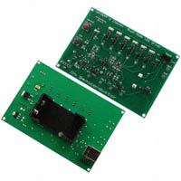
Figure 1. CAT3649 Evaluation Board
Figure 2. Ambient Light Sensor Mode Block Diagram
© Semiconductor Components Industries, LLC, 2012
November, 2012 − Rev. 1
1
Publication Order Number:
EVBUM2164/D
�CAT3649AGEVB
Figure 3. CAT3649AGEVB Board Schematic
Table 1. BILL OF MATERIALS*
Manufacturer Part
Number
Substitution
Allowed
ON
Semiconductor
CAT3649HV3-GT2
No
3 x 3 mm
ON
Semiconductor
NOA1211
No
-
CUDFN
Silicon
Laboratories
C8051F321
Yes
(5 V to 3.3 V)
-
1.6 x 1.6
ON
Semiconductor
CAT6218-330TDG
No
5 V Voltage Regulator
-
-
MLP-28
ON
Semiconductor
MC78M05ABDT
No
6
White LED
-
-
SOT-223
Lite-On
LTW-150TK
Yes
1
Red LED
-
-
DPAK-3
Everlight
EL17-215SURC
Yes
C1 to C4,
C6, C8,
C11, C13
8
Ceramic Capacitor
1 mF / 10 V,
X7R
10%
1206
Kemet
C0805C105K9RACTU
Yes
C7, C9,
C10, C16,
C14
5
Ceramic Capacitor
100 nF
10%
0805
AVX
0805ZC104KAT2A
Yes
C5
1
Ceramic Capacitor
47 nF
10%
0805
AVX
08053C473KAT2A
Yes
C15
1
Tantalum Capacitor
10 mF/10V
10%
0805
Vishay
TM8R106K010UBA
Yes
Designator
Value
Tolerance
Qty
Description
U1
1
6 Channel LED Driver
Footprint
Manufacturer
-
-
TQFN16
U2
1
Ambient Light Sensor
-
-
U3
1
8 bit Microcontroller
-
U4
1
Low Dropout Regulator
U5
1
D1 to D6
D7
*All products listed are Pb−free.
http://onsemi.com
2
�CAT3649AGEVB
Table 1. BILL OF MATERIALS*
Designator
Qty
Description
R1
1
SMD Resistor
R2
1
R3
1
R4, R5
Manufacturer
Manufacturer Part
Number
Substitution
Allowed
Vishay
RL0805K100-1
Yes
1210
Vishay
RL0805K004.7-1
Yes
0805
Vishay
RL0805K180-1
Yes
1%
0805
Vishay
RL0805K022-1
Yes
1/8 W, 100 kW
1%
0805
Vishay
RL0805K100-1
Yes
1/8 W, 200 W
1%
0805
Vishay
RL0805E200-1
Yes
Value
Tolerance
Footprint
1/8 W, 100 kW
1%
0805
SMD Resistor
1/8 W, 4.7 kW
1%
SMD Resistor
1/8 W, 180 W
1%
2
SMD Resistor
1/8 W, 22 kW
R6
1
SMD Resistor
R7
1
SMD Resistor
R10
1
SMD Resistor
1/8 W, 0.5 W
1%
0805
Yageo
RL0805FR-070R5L
Yes
J1 to J6,
J8 to J11
10
3-pin Header Connector,
0.1”, Single Strip
-
-
1.54 mm x
4.62 mm
MMM
2303-6211TG
Yes
J7
1
2-pin Header Connector,
0.1”, Single Strip
-
-
1.54 mm x
3.08 mm
MMM
2302-6211TG
Yes
ISP
1
5-pin Header Connector,
0.1”, Single Strip
-
-
1.54 mm x
7.70 mm
MMM
2305-6211TG
Yes
T1 – T8
8
Pin Receptacle (Test
Points)
-
-
1.54 mm x
1.54 mm
Mil-Max
Various
Yes
K1
1
Slide Switch, SPDT
-
-
11.60 mm x
4.00 mm
E-Switch
EG1218
Yes
SW1,
SW2
2
Pushbutton
-
-
3.50 mm x
6.00 mm
Schukat
DTS31N
Yes
BTH
1
Battery Holder 9 V
-
-
53.90 mm x
29.60 mm
Keystone
1294K-ND
Yes
*All products listed are Pb−free.
Operating Procedure
The CAT3649EVAL board can be configured in two
operating modes: stand−alone or PC−controlled.
In both operating modes, the supply source for the VIN
rail is selected by the jumper J10 to be either 5 V or 3.3 V.
Table 2 shows the configurations for jumper J10 to set the
VIN voltage.
The EN/DIS pushbutton allows the user to enable or to
shutdown the CAT3649 device.
The DIM pushbutton allows the user to program the LED
current in 32 discrete values. On each press on this
pushbutton, the “ADIM” input receives a 50 ms pulse. On
the rising edge of the pulse, the LED current is decreased by
3.2% from full scale.
The user can obtain the same effect by continuously
holding the DIM pushbutton down. For each 0.4 second
interval, the “ADIM” input of the device will receive a pulse.
Table 2. VIN SELECTION
J10
VIN
1−2
5V
2−3
3.3 V
PC Controlled
The CAT3649 EVAL board is equipped with a 8−bit
microcontroller and can be connected to the PC via USB
interface using a USB A/B type cable. This cable can be
obtained from a local electronics supply store.
The jumper J11 must be set in (1−2) position for USB
power operation.
The jumpers J8 and J9 must be set to (2−3) position to for
control of EN/DIS, ADIM, and PWM via USB.
In this mode, the board is powered from the USB
interface.
The GUI commands are described in the section
“Graphical User Interface (GUI)”.
Stand−alone
In this configuration, only the “Analog dimming”
function can be tested.
The Ambient Light Sensor (ALS) is disabled in this mode.
The jumper J11 must be set in (2−3) position for
stand−alone operation power.
The jumpers J8 and J9 must be set to (2−3) position to use
onboard pushbuttons EN/DIS and ADIM.
The evaluation board can be powered either from an
on−board 9 V supply (9 V alkaline battery) or from an
external supply applied between VBAT and GND test points
(located on the bottom side of the board, near the pins for the
battery holder).
http://onsemi.com
3
�CAT3649AGEVB
Graphical User Interface (GUI)
After connecting the CAT3649 EVAL board to the PC via
USB cable, the user can run the program
CAT3649EVAL.exe.
If the program is started without the USB connection, the
following message is displayed: “The CAT3649EVAL
Board is not detected!”.
The CAT3649 operating mode is selected by pressing one
of the “check” buttons “PWM” or “ADIM”.
If the option button “Select” of the frame of the Ambient
Light Sensor is pressed while in PWM mode, the “Gain”
frame will be enabled.
In this frame only the “Power Down” option is selected,
because the “Ambient Light Sensor”, at this moment, is off.
(Figure 9).
The user can select one of the options “Medium” or “Low”
corresponding at the LED’s intensity level domain.
(Figure 10). Depending of the light’s intensity exposed to
the sensor, the LEDs will light proportionally.
Operating mechanism is as follows:
The sensor outputs a current proportional to the ambient
light. This current is converted to an output voltage by
resistor R6. The output voltage is applied to the input of the
10−bit ADC (Analog to Digital Convertor) from the
microcontroller.
The microcontroller converts the digital value, received
from ADC, into a PWM signal applied to the CAT3649 LED
Driver.
CAT3649 controls the six LEDs’ intensity.
PWM Operation Mode
At start−up, on the GUI is selected, automatically, the
PWM mode of operation (as shown on Figure 4).
In this mode, the user can increase/decrease the LEDs
intensity by moving the potentiometer cursor or by pressing
the keys “−>” and “