Test Procedure for the CCR120PS3GEVK Evaluation Kit
CAUTION: VERY HIGH VOLTAGE MAY CAUSE SEVERE INJURY OR
DEATH
1
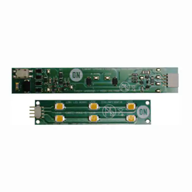
Devices under test
-
Driver board CCR120PS3AGEVB
-
LED board CCR120PS3BGEVB
1/24/2014
1
www.onsemi.com
�2
Basic functionality tests
Basic functional tests described below demonstrate fundamental working operation of driver and LED board. No special
skills are needed, however test person must be careful of hazardous voltage presented in test circuit.
2.1 Basic operation test
Test equipment required:
-
Galvanic-isolated AC power supply, output voltage adjustable from 100 - 130 VAC.
-
RMS multi-meter (AC voltage range up to 200V or more, AC current range up to 200mA or more)
Test sequence:
1. Turn ON AC power supply (not connected to the driver board), set its output voltage to 120 VAC using
multi-meter, turn it OFF afterwards.
2. Connect LED board to driver board.
3. Connect AC power supply output to the driver board input, so that AC input current is measured by
multi-meter.
AC power supply
0 - 130 V AC
~
Ammeter
[ARMS]
~
`
4. Turn AC power supply ON again
1/24/2014
2
www.onsemi.com
�5. All LEDs on LED board shall illuminate, no flicker should be noticeable, AC input current should be
around 70 mA. Note: Intensity of light emitted by LEDs is relatively high, use appropriate eye
protection during testing and/or avoid looking directly into lights.
6. Vary AC input voltage in a range from 100 up to 130 VAC, no light interruptions or flicker should be
observed, though certain small brightness variation should be noticed—this is normal.
3
Advanced functionality tests
Advanced functionality tests described below demonstrate detailed functionality of the driver and the LED board in ways
beyond the basic functionality tests. Certain test personnel skills are expected, and test person must be careful of hazardous
voltage presented in circuit.
3.1 Switching levels test
This test can be used for verification of driver board correct operation. Particular switching voltage levels as well as current
limitation levels are measured.
Test equipment required:
-
Galvanic-isolated AC power supply, output voltage adjustable over range from 60 - 130 VAC
-
RMS multi-meter (AC voltage range up to 200V or more)
-
Oscilloscope with two or more channels
-
Two differential voltage probes with maximum common and differential voltage 300V or more (because
of insulated AC power supply usage and common ground reference point during test, one differential
probe can be replaced by 1/10 or 1/100 oscilloscope probe, however differential probes are highly
recommended)
-
One current probe (capable of measuring of DC+AC current of 200mA or more)
Test sequence:
1. Turn ON AC power supply (not connected to the driver board), set its output voltage to 65 VAC using
multi-meter, turn it OFF afterwards.
2. Connect LED board to driver board.
3. Connect AC power supply output to the driver board.
4. Connect one differential probe to the driver board AC input, this will be used also as a oscilloscope
trigger source (expected signal level is up to 380 V peak-to-peak).
5. Clamp current probe around one of the AC input wires connected to the driver board. Set probe and
scope to 50Ω termination (depending on used current probe type, expected current level is up to 200
mA peak-to-peak).
1/24/2014
3
www.onsemi.com
�6. Connect second differential probe between anode of LED string #1 and cathode of LED string #2
(expected voltage level is up to 130 V).
AC power supply
0 - 130 V AC
~
Oscilloscope
Ch1
Ch3
~
`
Ch2
AC/DC current probe
differential probe
differential probe
7. Set all used oscilloscope channels according expected signal levels.
1/24/2014
4
www.onsemi.com
�8. Turn AC power supply ON again.
9. Inspect input current waveform: apparent, almost stable input current level around 55 mA should be
noticeable. Input current transitions should be located near to the point where driver board AC input
voltage crosses 56 V (one LED string forward voltage—both LED strings are connected in parallel at
this low of voltage).
10. Inspect voltage waveform measured by differential probe connected according to Step 6: nearly stable
voltage level around 56 V should be noticeable. Transition between this voltage and zero should
follow driver board AC input voltage (both polarities).
1/24/2014
5
www.onsemi.com
�11. Increase AC input voltage to 80 VAC.
12. Inspect input current waveform: two different current levels around 50 mA and 85 mA should be
noticeable. Transition between those two current levels should be located near to the point where
driver board AC input voltage crosses 100 V.
13. Inspect voltage waveform measured by differential probe connected according to Step 6: as in point
#10, an almost stable voltage level around 56 V should be noticeable. Transition between this voltage
and zero should follow driver board AC input voltage (both polarities).
1/24/2014
6
www.onsemi.com
�14. Increase AC input voltage to 120 VAC.
15. Inspect input current waveform: two different current levels around 50 mA (though relatively short in
time) and 85 mA should be still noticeable. Transition origin between those two current levels should
be located near to the point where driver board AC input voltage crosses 100 V. Note that, certain
peak changes in current are present right at the moment when LED string connection changes from
parallel to serial and vice versa.
16. Inspect voltage waveform measured by differential probe connected according to Step 6: two nearly
stable voltage levels around 56 V and 112 V should be noticeable. Transition between both voltage
levels should be located near to the point where driver board AC input voltage crosses 120V (both
polarities). In fact, lower voltage level indicates the time interval during which both LED strings are
connected in parallel, higher voltage level indicates the time interval when both LED string are
connected in series.
1/24/2014
7
www.onsemi.com
�3.2 Efficiency measurement
This test evaluates driver board efficiency, and if test equipment is available, checks power factor and THD.
Test equipment required:
-
Galvanic-isolated AC power supply, output voltage adjustable from 100 - 130 VAC
-
AC power analyzer (AC voltage range up to 150V AC or more, AC current range up to 100 mA or more).
Note: If no AC power analyzer is available it can be replaced by combination of two RMS multi-meters
(AC voltage range up to 150 V or more, AC current range up to 100 mA or more). Input power can be
calculated by multiplication of AC input voltage and AC input current, however, this provides apparent
input power figures instead of real input power. Additionally, neither power factor nor AC input current
THD can be measured using two multi-meters method.
-
RMS voltmeter (DC voltage range up to 150 V or more) – used for driver board output voltage
measurement. If available, it would be better to use two of them, so that voltages of both LED strings
can be measured simultaneously, though this is not required.
1/24/2014
8
www.onsemi.com
�-
RMS ammeter (DC current range up to 100 mA or more) – used for driver board output/LED current
measurement. For similar reasons as having two RMS voltmeters, two instances would be preferable,
allowing quicker measurements.
Test sequence:
1. Turn ON AC power supply (not connected to the driver board), set its output voltage to 120 VAC using
multi-meter, turn it OFF afterwards.
2. Connect LED board to driver board.
3. Connect AC power supply output to the AC power analyzer input.
4. Connect AC power analyzer input to the driver board AC input.
5. Connect LED board to driver board using wires so that LED string #1 current and voltage can be
measured using RMS voltmeter and RMS ammeter. If second RMS voltmeter and RMS ammeter are
available, the tester may connect these to LED string #2 in the same fashion.
AC power
analyzer
AC power supply
0 - 130 V AC
~
~
`
Voltmeter
[VRMS]
Ammeter
[ARMS]
6. Turn AC power supply ON again. Allow circuit to run for 2 minutes to stabilize for thermal settling before
taking measurements.
7. Write down real input power value measured by AC power analyzer, check also power factor and THD
parameter in case of interest (Expected PF is ~0.99 and expected THD is ~12-15%).
1/24/2014
9
www.onsemi.com
�8. Write down LED string #1 RMS voltage and RMS current. Calculate LED string #1 output power by
multiplying these values. If second RMS voltmeter and RMS ammeter were used, write down these
values for LED string #2 and multiply for output power, then skip to Step 14.
9. Turn AC power supply OFF.
10. Rearrange LED board connection to driver board so that LED string #2 current and voltage can be
measured.
AC power
analyzer
AC power supply
0 - 130 V AC
~
~
`
Voltmeter
[VRMS]
Ammeter
[ARMS]
11. Turn ac power supply ON again. Allow circuit to run for 2 minutes to stabilize for thermal settling before
taking measurements.
12. Check that AC input voltage is still 120VAC.
13. Write down LED string #2 RMS voltage and RMS current. Calculate output power multiplying those
values.
14. Calculate driver board efficiency using following formula (expected efficiency is ~77-79%):
1/24/2014
10
www.onsemi.com
�
很抱歉,暂时无法提供与“CCR120PS3GEVK”相匹配的价格&库存,您可以联系我们找货
免费人工找货