LCD and Camera EMI Filter Array with ESD Protection CM1630
Features
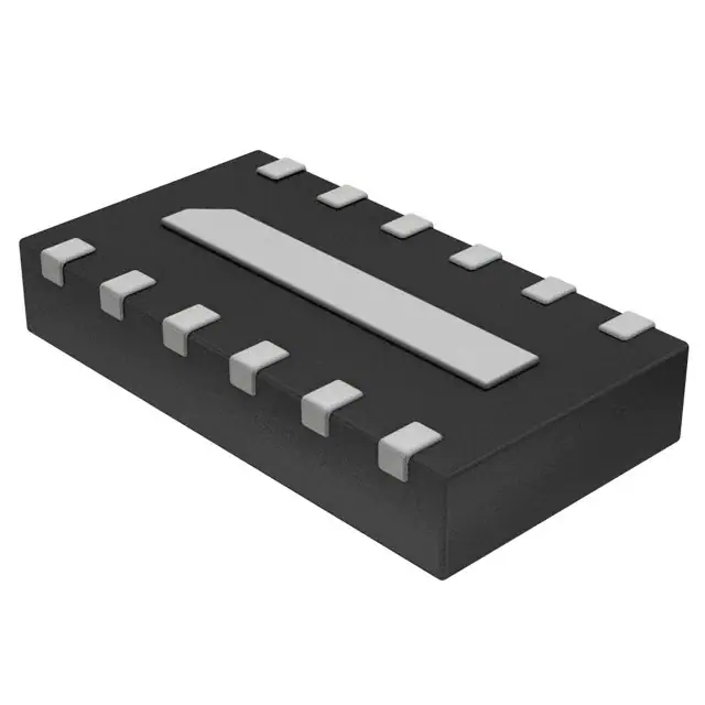
• • • • • • Four, six and eight channels of EMI filtering with integrated ESD protection Pi-style EMI filters in a capacitor-resistorcapacitor (C-R-C) network ±15kV ESD protection on each channel (IEC 61000-4-2 Level 4, contact discharge) ±30kV ESD protection on each channel (HBM) Greater than 25dB attenuation (typical) at 1 GHz UDFN package with 0.40mm lead pitch: • 4-ch. = 8-lead UDFN • 6-ch. = 12-lead UDFN • 8-ch. = 16-lead UDFN Tiny UDFN package size: • 8-lead: 1.7mm x 1.35mm x 0.5mm • 12-lead: 2.5mm x 1.35mm x 0.5mm • 16-lead: 3.3mm x 1.35mm x 0.5mm Increased robustness against vertical impacts during manufacturing process Lead-free version available
Product Description
The CM1630 is a family of pi-style EMI filter arrays with ESD protection, which integrates four, six and eight filters (C-R-C) in small form factor UDFN 0.40mm pitch packages. The CM1630 has component values of 8.5pF-100Ω-8.5pF per channel. The CM1630 has a cut-off frequency of 200MHz and can be used in applications with data rates up to 80Mbps. The parts include ESD diodes on every pin, which provide a very high level of protection for sensitive electronic components that may be subjected to electrostatic discharge (ESD). The ESD protection diodes safely dissipate ESD strikes of ±15kV, well beyond the maximum requirement of the IEC61000-4-2 international standard. Using the MIL-STD-883 (Method 3015) specification for Human Body Model (HBM) ESD, the pins are protected for contact discharges at greater than ±30kV. These devices are particularly well-suited for portable electronics (e.g. wireless handsets, PDAs, notebook computers) because of their small package and easy-to-use pin assignments. In particular, the CM1630 is ideal for EMI filtering and protecting data and control lines for the I/O data ports, LCD display and camera interface in mobile handsets. The CM1630 is housed in space-saving, low-profile 8-, 12- and 16-lead UDFN packages with a 0.4mm pitch and is available with lead-free finishing. This new small UDFN package provides up to 42% board space savings vs. the 0.50mm pitch UDFN packages.
•
• •
Applications
• • • • • • LCD and Camera data lines in mobile handsets I/O port protection for mobile handsets, notebook computers, PDAs etc. EMI filtering for data ports in cell phones, PDAs or notebook computers. Wireless handsets Handheld PCs/PDAs LCD and camera modules
©2010 SCILLC. All rights reserved. May 2010 – Rev. 2
Publication Order Number: CM1630/D
�CM1630
Electrical Schematic
1 of 4, 6 or 8 EMI/RFI Filter Channels with Integrated ESD Protection
Rev.2 | Page 2 of 18 | www.onsemi.com
�CM1630
PIN DESCRIPTIONS
DEVICE PIN(s) -04 1 2 3 4 -06 1 2 3 4 5 6 -08 1 2 3 4 5 6 7 8 GND PAD NAME FILTER1 FILTER2 FILTER3 FILTER4 FILTER5 FILTER6 FILTER7 FILTER8 GND DESCRIPTION Filter + ESD Channel 1 Filter + ESD Channel 2 Filter + ESD Channel 3 Filter + ESD Channel 4 Filter + ESD Channel 5 Filter + ESD Channel 6 Filter + ESD Channel 7 Filter + ESD Channel 8 Device Ground DEVICE PIN(s) -04 8 7 6 5 -06 12 11 10 9 8 7 -08 16 15 14 13 12 11 10 9 NAME FILTER1 FILTER2 FILTER3 FILTER4 FILTER5 FILTER6 FILTER7 FILTER8 DESCRIPTION Filter + ESD Channel 1 Filter + ESD Channel 2 Filter + ESD Channel 3 Filter + ESD Channel 4 Filter + ESD Channel 5 Filter + ESD Channel 6 Filter + ESD Channel 7 Filter + ESD Channel 8
Ordering Information
PART NUMBERING INFORMATION
Lead-free Finish Pins 8 12 16 Package UDFN-8 UDFN-12 UDFN-16 Ordering Part Number1 CM1630-04DE CM1630-06DE CM1630-08DE Part Marking TE P30E P308E
Note 1: Parts are shipped in Tape & Reel form unless otherwise specified.
Specifications
ABSOLUTE MAXIMUM RATINGS
PARAMETER Storage Temperature Range DC Power per Resistor DC Package Power Rating RATING -65 to +150 100 500 UNITS °C mW mW
Rev. 2 | Page 3 of 18 | www.onsemi.com
�CM1630
STANDARD OPERATING CONDITIONS
PARAMETER Operating Temperature Range RATING -40 to +85 UNITS °C
ELECTRICAL OPERATING CHARACTERISTICS (SEE NOTE1)
SYMBOL R CTOTAL C VDIODE ILEAK VSIG PARAMETER Resistance Total Channel Capacitance Capacitance C1 Standoff Voltage Diode Leakage Current (reverse bias) Signal Clamp Voltage Positive Clamp Negative Clamp In-system ESD Withstand Voltage a) Human Body Model, MIL-STD-883, Method 3015 b) Contact Discharge per IEC 61000-4-2 Level 4 Dynamic Resistance Positive Negative Cut-off Frequency ZSOURCE=50Ω, ZLOAD=50Ω Absolute Attenuation @ 1GHz from 0dB Level Channel R = 100Ω, Channel C = 8.5pF ZSOURCE = 50Ω, Z LOAD = 50Ω, DC Bias = 0V; Notes 1 and 3 50Ω, DC Bias = 0V; Notes 1 and 3 At 2.5VDC Reverse Bias, 1MHz, 30mVAC At 2.5VDC Reverse Bias, 1MHz, 30mVAC IDIODE=10μA VDIODE=+3.3V ILOAD = 10mA ILOAD = -10mA Note 2 ±30 ±15 2.3 0.9 200 30 kV kV Ω Ω MHz dB 5.6 -0.4 CONDITIONS MIN 80 14 7 TYP 100 17 8.5 6.0 0.1 1.0 MAX 120 22 11 UNITS Ω pF pF V μA V V
6.8 -0.8
VESD
RDYN
f
C
A1GHz
A800MHz - 6GHz Absolute Attenuation @ 800MHz to 6GHz from 0dB ZSOURCE = 50Ω, Z LOAD =
Level
25
dB
Note 1: TA=25°C unless otherwise specified. Note 2: ESD applied to input and output pins with respect to GND, one at a time. Note 3: Attenuation / RF curves characterized by a network analyzer using microprobes.
Rev.2 | Page 4 of 18 | www.onsemi.com
�CM1630
Performance Information
Typical Filter Performance (TA=25°C, DC Bias=0V, 50 Ohm Environment)
Figure 1. Insertion Loss vs. Frequency (FILTER1 Input to GND, CM1436-04DE)
Figure 2. Insertion Loss vs. Frequency (FILTER2 Input to GND, CM1436-04DE)
Rev. 2 | Page 5 of 18 | www.onsemi.com
�CM1630
Performance Information (cont’d)
Typical Filter Performance (TA=25°C, DC Bias=0V, 50 Ohm Environment)
Figure 3. Insertion Loss vs. Frequency (FILTER3 Input to GND, CM1436-04DE)
Figure 4. Insertion Loss vs. Frequency (FILTER4 Input to GND, CM1436-04DE)
Rev.2 | Page 6 of 18 | www.onsemi.com
�CM1630
Performance Information (cont’d)
Typical Filter Performance (TA=25°C, DC Bias=0V, 50 Ohm Environment)
Figure 5. Insertion Loss vs. Frequency (FILTER1 Input to GND, CM1436-06DE)
Figure 6. Insertion Loss vs. Frequency (FILTER2 Input to GND, CM1436-06DE)
Rev. 2 | Page 7 of 18 | www.onsemi.com
�CM1630
Performance Information (cont’d)
Typical Filter Performance (TA=25°C, DC Bias=0V, 50 Ohm Environment)
Figure 7. Insertion Loss vs. Frequency (FILTER3 Input to GND, CM1436-06DE)
Figure 8. Insertion Loss vs. Frequency (FILTER4 Input to GND, CM1436-06DE)
Rev.2 | Page 8 of 18 | www.onsemi.com
�CM1630
Performance Information (cont’d)
Typical Filter Performance (TA=25°C, DC Bias=0V, 50 Ohm Environment)
Figure 9. Insertion Loss vs. Frequency (FILTER5 Input to GND, CM1436-06DE)
Figure 10. Insertion Loss vs. Frequency (FILTER6 Input to GND, CM1436-06DE)
Rev. 2 | Page 9 of 18 | www.onsemi.com
�CM1630
Performance Information (cont’d)
Typical Filter Performance (TA=25°C, DC Bias=0V, 50 Ohm Environment)
Figure 11. Insertion Loss vs. Frequency (FILTER1 Input to GND, CM1436-08DE)
Figure 12. Insertion Loss vs. Frequency (FILTER2 Input to GND, CM1436-08DE)
Rev.2 | Page 10 of 18 | www.onsemi.com
�CM1630
Performance Information (cont’d)
Typical Filter Performance (TA=25°C, DC Bias=0V, 50 Ohm Environment)
Figure 13. Insertion Loss vs. Frequency (FILTER3 Input to GND, CM1436-08DE)
Figure 14. Insertion Loss vs. Frequency (FILTER4 Input to GND, CM1436-08DE)
Rev. 2 | Page 11 of 18 | www.onsemi.com
�CM1630
Performance Information (cont’d)
Typical Filter Performance (TA=25°C, DC Bias=0V, 50 Ohm Environment)
Figure 15. Insertion Loss vs. Frequency (FILTER5 Input to GND, CM1436-08DE)
Figure 16. Insertion Loss vs. Frequency (FILTER6 Input to GND, CM1436-08DE)
Rev.2 | Page 12 of 18 | www.onsemi.com
�CM1630
Performance Information (cont’d)
Typical Filter Performance (TA=25°C, DC Bias=0V, 50 Ohm Environment)
Figure 17. Insertion Loss vs. Frequency (FILTER7 Input to GND, CM1436-08DE)
Figure 18. Insertion Loss vs. Frequency (FILTER8 Input to GND, CM1436-08DE)
Rev. 2 | Page 13 of 18 | www.onsemi.com
�CM1630
Performance Information (cont’d)
Typical Diode Capacitance vs. Input Voltage
Figure 19. Filter Capacitance vs. Input Voltage (normalized to capacitance at 2.5VDC and 25°C)
Rev.2 | Page 14 of 18 | www.onsemi.com
�CM1630
Mechanical Details
UDFN-08 Mechanical Specifications Dimensions for the CM1630 supplied in a 8-lead, 0.4mm pitch UDFN package are presented below.
PACKAGE DIMENSIONS
Package JEDEC No. Leads Millimeters Dim. Min A A1 A3 b D D2 E E2 e K L # per tape and reel 0.20 0.15 0.25 0.35 0.15 1.60 1.10 1.25 0.30 0.45 0.00 Nom 0.50 0.02 0.127 REF 0.20 1.70 1.20 1.35 0.40 0.40 BSC 0.25 1.80 1.30 1.45 0.50 Max 0.55 0.05 Min 0.018 0.000 Nom 0.020 0.001 Max 0.022 0.002 UDFN MO-229C 8 Inches
✝
0.005 REF 0.006 0.063 0.043 0.049 0.012 0.008 0.067 0.047 0.053 0.016 0.010 0.071 0.051 0.057 0.020
0.016 BSC 0.008 0.006 0.010 0.014
3000 pieces
Dimensions for 8-Lead, 0.4mm pitch UDFN package
Controlling dimension: millimeters
=
This package is compliant with JEDEC standard MO-229C with the exception of the "D", "D2", "E", "E2", "K" and "L" dimensions as called out in the table above.
Rev. 2 | Page 15 of 18 | www.onsemi.com
�CM1630
Mechanical Details (cont’d)
UDFN-12 Mechanical Specifications Dimensions for the CM1630 suplied in a 12-lead, 0.4mm pitch UDFN package are presented below.
PACKAGE DIMENSIONS
Package JEDEC No. Leads Millimeters Dim. Min A A1 A3 b D D2 E E2 e K L # per tape and reel 0.20 0.15 0.25 0.35 0.15 2.40 1.90 1.25 0.30 0.45 0.00 Nom 0.50 0.02 0.127 REF 0.20 2.50 2.00 1.35 0.40 0.40 BSC 0.25 2.60 2.10 1.45 0.50 Max 0.55 0.05 Min 0.018 0.000 Nom 0.020 0.001 Max 0.022 0.002 UDFN MO-229C 12 Inches
✝
0.005 REF 0.006 0.094 0.075 0.049 0.012 0.008 0.098 0.079 0.053 0.016 0.010 0.102 0.083 0.057 0.020
0.016 BSC 0.008 0.006 0.010 0.014
3000 pieces
Dimensions for 12-Lead, 0.4mm pitch UDFN package
Controlling dimension: millimeters
=
This package is compliant with JEDEC standard MO-229C with the exception of the "D", "D2", "E", "E2", "K" and "L" dimensions as called out in the table above.
Rev.2 | Page 16 of 18 | www.onsemi.com
�CM1630
Mechanical Details (cont’d)
UDFN-16 Mechanical Specifications Dimensions for the CM1630 supplied in a 16-lead, 0.4mm pitch UDFN package are presented below.
PACKAGE DIMENSIONS
Package JEDEC No. Leads Millimeters Dim. Min A A1 A3 b D D2 E E2 e K L # per tape and reel 0.20 0.15 0.25 0.35 0.15 3.20 2.70 1.25 0.30 0.45 0.00 Nom 0.50 0.02 0.127 REF 0.20 3.30 2.80 1.35 0.40 0.40 BSC 0.25 3.40 2.90 1.45 0.50 Max 0.55 0.05 Min 0.018 0.000 Nom 0.020 0.001 Max 0.022 0.002 UDFN MO-229C 16 Inches
✝
0.005 REF 0.006 0.126 0.106 0.049 0.012 0.008 0.130 0.110 0.053 0.016 0.010 0.134 0.114 0.057 0.020
0.016 BSC 0.008 0.006 0.010 0.014
3000 pieces
Dimensions for 16-Lead, 0.4mm pitch UDFN package
Controlling dimension: millimeters
This package is compliant with JEDEC standard MO-229C with the exception of the "D", "D2", "E", "E2", "K" and "L" dimensions as called out in the table above.
✝
Rev. 2 | Page 17 of 18 | www.onsemi.com
�CM1630
ON Semiconductor and are registered trademarks of Semiconductor Components Industries, LLC (SCILLC). SCILLC reserves the right to make changes without further notice to any products herein. SCILLC makes no warranty, representation or guarantee regarding the suitability of its products for any particular purpose, nor does SCILLC assume any liability arising out of the application or use of any product or circuit, and specifically disclaims any and all liability, including without limitation special, consequential or incidental damages. “Typical” parameters which may be provided in SCILLC data sheets and/or specifications can and do vary in different applications and actual performance may vary over time. All operating parameters, including “Typicals” must be validated for each customer application by customer's technical experts. SCILLC does not convey any license under its patent rights nor the rights of others. SCILLC products are not designed, intended, or authorized for use as components in systems intended for surgical implant into the body, or other applications intended to support or sustain life, or for any other application in which the failure of the SCILLC product could create a situation where personal injury or death may occur. Should Buyer purchase or use SCILLC products for any such unintended or unauthorized application, Buyer shall indemnify and hold SCILLC and its officers, employees, subsidiaries, affiliates, and distributors harmless against all claims, costs, damages, and expenses, and reasonable attorney fees arising out of, directly or indirectly, any claim of personal injury or death associated with such unintended or unauthorized use, even if such claim alleges that SCILLC was negligent regarding the design or manufacture of the part. SCILLC is an Equal Opportunity/Affirmative Action Employer. This literature is subject to all applicable copyright laws and is not for resale in any manner.
PUBLICATION ORDERING INFORMATION
LITERATURE FULFILLMENT: Literature Distribution Center for ON Semiconductor P.O. Box 5163, Denver, Colorado 80217 USA Phone: 303-675-2175 or 800-344-3860 Toll Free USA/Canada Fax: 303-675-2176 or 800-344-3867 Toll Free USA/Canada Email: orderlit@onsemi.com N. American Technical Support: 800-282-9855 Toll Free USA/Canada Europe, Middle East and Africa Technical Support: Phone: 421 33 790 2910 Japan Customer Focus Center Phone: 81-3-5773-3850 ON Semiconductor Website: www.onsemi.com Order Literature: http://www.onsemi.com/orderlit For additional information, please contact your local Sales Representative
Rev.2 | Page 18 of 18 | www.onsemi.com
�