DM7473N

DM7473N

  • 厂商:

    ONSEMI(安森美)

  • 封装:

    DIP-14

  • 描述:

    IC FF JK TYPE DUAL 1BIT 14DIP

  • 详情介绍
  • 数据手册
  • 价格&库存
DM7473N 数据手册
Revised July 2001 DM7473 Dual Master-Slave J-K Flip-Flops with Clear and Complementary Outputs General Description This device contains two independent positive pulse triggered J-K flip-flops with complementary outputs. The J and K data is processed by the flip-flops after a complete clock pulse. While the clock is LOW the slave is isolated from the master. On the positive transition of the clock, the data from the J and K inputs is transferred to the master. While the clock is HIGH the J and K inputs are disabled. On the negative transition of the clock, the data from the master is transferred to the slave. The logic states of the J and K inputs must not be allowed to change while the clock is HIGH. Data transfers to the outputs on the falling edge of the clock pulse. A LOW logic level on the clear input will reset the outputs regardless of the logic states of the other inputs. Ordering Code: Order Number DM7473N Package Number N14A Package Description 14-Lead Plastic Dual-In-Line Package (PDIP), JEDEC MS-001, 0.300" Wide Connection Diagram Function Table Inputs Outputs CLR CLK J K Q L X X L H L L Q0 Q0 H L H L L H L H H H H H H H X Q Toggle H = HIGH Logic Level L = LOW Logic Level X = Either LOW or HIGH Logic Level = Positive pulse data. the J and K inputs must be held constant while the clock is HIGH. Data is transferred to the outputs on the falling edge of the clock pulse. Q0 = The output logic level before the indicated input conditions were established. Toggle = Each output changes to the complement of its previous level on each HIGH level clock pulse. © 2001 Fairchild Semiconductor Corporation DS006525 www.fairchildsemi.com DM7473 Dual Master-Slave J-K Flip-Flops with Clear and Complementary Outputs September 1986 DM7473 Absolute Maximum Ratings(Note 1) Supply Voltage Note 1: The “Absolute Maximum Ratings” are those values beyond which the safety of the device cannot be guaranteed. The device should not be operated at these limits. The parametric values defined in the Electrical Characteristics tables are not guaranteed at the absolute maximum ratings. The “Recommended Operating Conditions” table will define the conditions for actual device operation. 7V Input Voltage 5.5V 0°C to +70°C Operating Free Air Temperature Range −65°C to +150°C Storage Temperature Range Recommended Operating Conditions Symbol Parameter Min Nom Max 4.75 5 5.25 Units VCC Supply Voltage VIH HIGH Level Input Voltage VIL LOW Level Input Voltage 0.8 V IOH HIGH Level Output Current −0.4 mA V 2 IOL LOW Level Output Current fCLK Clock Frequency (Note 3) 0 tW Pulse Width Clock HIGH 20 (Note 3) Clock LOW 47 Clear LOW 25 tSU Input Setup Time (Note 2)(Note 3) 0↑ tH Input Hold Time (Note 2)(Note 3) 0↓ TA Free Air Operating Temperature 0 V 16 mA 15 MHz ns ns ns °C 70 Note 2: The symbol (↑, ↓) indicates the edge of the clock pulse is used for reference: (↑) for rising edge, (↓) for falling edge. Note 3: TA = 25°C and V CC = 5V. Electrical Characteristics over recommended operating free air temperature range (unless otherwise noted) Symbol Parameter Conditions VI Input Clamp Voltage VCC = Min, II = −12 mA VOH HIGH Level VCC = Min, IOH = Max Output Voltage VIL = Max, VIH = Min VOL LOW Level VCC = Min, IOL = Max Output Voltage VIH = Min, VIL = Max II Input Current @ Max Input Voltage VCC = Max, VI = 5.5V IIH HIGH Level VCC = Max Input Current VI = 2.4V IIL LOW Level Input VCC = Max Current VI = 0.4V IOS Short Circuit Output Current VCC = Max (Note 5) ICC Supply Current VCC = Max, (Note 6) Min 2.4 Typ (Note 4) Max Units −1.5 V 3.4 V 0.2 0.4 V 1 mA J, K 40 Clock 80 Clear 80 J, K −1.6 Clock −3.2 Clear −3.2 −18 18 µA mA −55 mA 34 mA Note 4: All typicals are at VCC = 5V, TA = 25°C. Note 5: Not more than one output should be shorted at a time. Note 6: With all outputs OPEN, ICC is measured with the Q and Q outputs HIGH in turn. At the time of measurement the clock input grounded. Switching Characteristics Symbol at VCC = 5V and TA = 25°C Parameter From (Input) RL = 400Ω, CL = 15 pF To (Output) Min Units Max fMAX Maximum Clock Frequency tPHL Propagation Delay Time HIGH-to-LOW Level Output Clear to Q 40 ns tPLH Propagation Delay Time LOW-to-HIGH Level Output Clear to Q 25 ns tPHL Propagation Delay Time HIGH-to-LOW Level Output Clock to Q or Q 40 ns tPLH Propagation Delay Time LOW-to-HIGH Level Output Clock to Q or Q 25 ns www.fairchildsemi.com 15 2 MHz DM7473 Dual Master-Slave J-K Flip-Flops with Clear and Complementary Outputs Physical Dimensions inches (millimeters) unless otherwise noted 14-Lead Plastic Dual-In-Line Package (PDIP), JEDEC MS-001, 0.300" Wide Package Number N14A Fairchild does not assume any responsibility for use of any circuitry described, no circuit patent licenses are implied and Fairchild reserves the right at any time without notice to change said circuitry and specifications. LIFE SUPPORT POLICY FAIRCHILD’S PRODUCTS ARE NOT AUTHORIZED FOR USE AS CRITICAL COMPONENTS IN LIFE SUPPORT DEVICES OR SYSTEMS WITHOUT THE EXPRESS WRITTEN APPROVAL OF THE PRESIDENT OF FAIRCHILD SEMICONDUCTOR CORPORATION. As used herein: 2. A critical component in any component of a life support device or system whose failure to perform can be reasonably expected to cause the failure of the life support device or system, or to affect its safety or effectiveness. 1. Life support devices or systems are devices or systems which, (a) are intended for surgical implant into the body, or (b) support or sustain life, and (c) whose failure to perform when properly used in accordance with instructions for use provided in the labeling, can be reasonably expected to result in a significant injury to the user. www.fairchildsemi.com 3 www.fairchildsemi.com
DM7473N
物料型号: - 型号:DM7473 - 
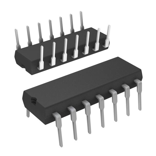
封装:14-Lead Plastic Dual-In-Line Package (PDIP), JEDEC MS-001, 0.300" Wide

器件简介: - 该设备包含两个独立的正脉冲触发的J-K触发器,具有互补输出。J和K数据在完整的时钟脉冲后由触发器处理。时钟为低电平时,从机与主机隔离。在时钟的正跳变期间,J和K输入的数据被传输到主机。在时钟为高电平时,J和K输入被禁用。在时钟的负跳变期间,主机的数据被传输到从机。在时钟为高电平时,不允许J和K输入的逻辑状态发生变化。数据在时钟脉冲的下降沿传输到输出。清除输入上的低电平将重置输出,而不管其他输入的逻辑状态。

引脚分配: - 连接图显示了各个引脚的功能,例如:01 GND, 02 CLK1, CLR1, K1, Ycc等。

参数特性功能详解部分包含了详细的电气特性表,包括供电电压、输入电压、工作温度范围等绝对最大额定值,以及推荐的操作条件,例如供电电压、高/低电平输入电压、输出电流等。

应用信息封装信息在文档中也有详细描述,包括物理尺寸和封装类型。
DM7473N 价格&库存

很抱歉,暂时无法提供与“DM7473N”相匹配的价格&库存,您可以联系我们找货

免费人工找货
DM7473N
  •  国内价格 香港价格
  • 25+8.4268325+1.08126

库存:0