www.fairchildsemi.com
FAN1582
3A Adjustable/Fixed Ultra Low Dropout
Linear Regulator
Features
Description
•
•
•
•
•
•
•
The FAN1582, FAN1582-1.5, and FAN1582-2.5 are ultra-low
dropout regulators with 3A output current capability. These
devices have been optimized for low voltage applications
including VTT bus termination, where transient response and
minimum input voltage are critical. The FAN1582 is ideal
for low voltage microprocessor applications requiring a regulated output from 1.3V to 5.7V with a power input supply
of 1.75V to 6.5V. The FAN1582-1.5 offers fixed 1.5V with
3A current capabilities for GTL+ bus VTT termination. The
FAN1582-2.5 offers fixed 2.5V with 3A current capability
for logic IC operation and processors while minimizing the
overall power dissipation.
Ultra Low dropout voltage, 0.4V typical at 3A
Remote sense operation
Fast transient response
Load regulation: 0.05% typical
0.5% initial accuracy
On-chip thermal limiting
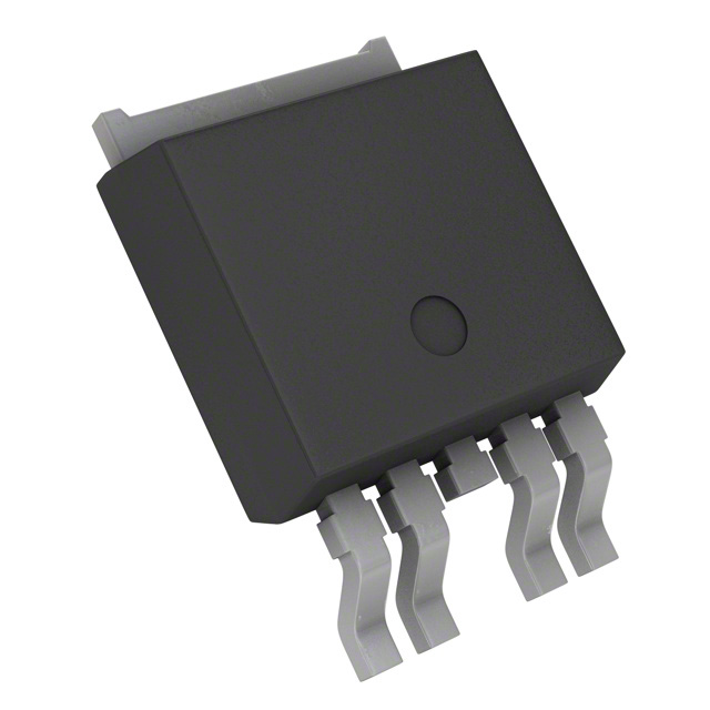
5-Pin TO-252 DPAK, and TO-263 packages
Applications
•
•
•
•
•
•
Support of GTL+ bus supply
Low voltage logic supply
Embedded Processor supplies
Split plane regulator
2.5V, and 1.8V Logic Families
DDR Termination Supply
Current limit ensures controlled short-circuit current. On-chip
thermal limiting provides protection against any combination
of overload and ambient temperature that would create excessive junction temperatures.
The FAN1582 series regulators are available in the 5-Pin
TO-252 DPAK, and TO-263 power packages.
Typical Applications
VIN = 3.3V
+
10µF
VIN = 3.3V
+
10µF
VCNTL = 5V
VIN
+
22µF
2.1V at 3A
VCNTL
Adj
2.5V at 3A
+
GND
1µF
FAN1582
VOUT
VSENSE
FAN1582–2.5
VOUT
VCNTL
VCNTL = 5V
VSENSE
VIN
+
124Ω
22µF
VIN = 5.75V
+
86.6Ω
10µF
VCNTL = 12V
VIN
VSENSE
FAN1582
VOUT
5V at 3A
VCNTL
Adj
+
124Ω
22µF
374Ω
Pentium is a registered trademark of Intel Corporation. PowerPC is a trademark of IBM Corporation.
REV. 1.1.3 11/9/03
�FAN1582
PRODUCT SPECIFICATION
1
2
S
ADJ
5-Lead Plastic TO-263
ΘJC=3°C/W*
Tab is out.
3
4
5
1
2
3
4
5
IN
1 2 3 4 5
OUT
1 2 3 4 5
CNTL
FRONT VIEW
S
FRONT VIEW
GND
FRONT VIEW
IN
FAN1582D-1.5, -2.5
CNTL
FAN1582D
FRONT VIEW
S
ADJ
OUT
CNTL
IN
FAN1582M-1.5, -2.5
OUT
FAN1582M
S
GND
OUT
CNTL
IN
Pin Assignments
5-Lead Plastic TO-252 DPAK
ΘJC=3°C/W*
Tab is out.
*With package soldered to 0.5 square inch copper area over backside ground plane or internal
power plane, θJA can vary from 30 °C/W to more than 40 °C/W. Other mounting techniques
can provide a thermal resistance lower than 30 °C/W.
Pin Definitions
Pin Number
Pin Name
Pin Function Descrition
1
VSense
2
ADJ/GND
3
VOUT
Output Voltage. This pin and the tab are output.
4
VCNTL
Control Voltage. This pin draws small-signal power to control the
FAN1582 circuitry. Connect to a voltage higher than VIN, as shown in the
applications circuits.
5
VIN
Remote Voltage Sense. Connect this pin to the load to permit true
remote sensing and avoid trace drops.
Adjust or Ground. On the FAN1582, this pin forms the feedback to
determine the output voltage. On the FAN1582-1.5 and -2.5, connect this
pin to ground.
Input Voltage.
Internal Block Diagram
4
VCNTL, Control
5 Vin, Power
Thermal
Shutdown
Current
Limit
Vref
2
Voltage Loop
Amplifier
3 Output
1 Sense
2 Adj
REV. 1.1.3 11/9/03
�PRODUCT SPECIFICATION
FAN1582
Absolute Maximum Ratings
Parameter
Min.
VIN
VCNTL
Operating Junction Temperature Range
0
Lead Temperature (Soldering, 10 sec.)
Storage Temperature Range
-65
Max.
Unit
7
V
13.2
V
125
°C
300
°C
150
°C
Electrical Characteristics
TJ=25°C, VOUT = VS, VADJ = 0V unless otherwise specified.
The • denotes specifications which apply over the specified operating temperature range.
Parameter
Reference Voltage3
Reference Voltage3
Adjustable Output Voltage
Output Voltage4
Output Voltage5
Line Regulation1,2
Load Regulation1,2
Dropout Voltage Minimum
(VCNTL–VOUT)
Dropout Voltage Minimum
(VIN–VOUT)
Dropout Voltage Minimum VIN
Current Limit
Control Pin Current
Adjust Pin Current3
Minimum Load Current
Ripple Rejection
Thermal Resistance, Junction to
Case
Thermal Regulation
Thermal Shutdown
Conditions
VIN = 2.0V, VCNTL = 2.75V,
IOUT = 10mA
2.05V ≤ VIN ≤ 5.5V,
2.7V ≤ VCNTL ≤ 12V,
10mA ≤ IOUT ≤ 3A
3V ≤ VIN ≤ 7V (function of Vout),
10mA ≤ IOUT ≤ 3A
3V ≤ VIN ≤ 7V, 10mA ≤ IOUT ≤ 3A
5.1V ≤ VIN ≤ 7V, 10mA ≤ IOUT ≤ 3A
1.75V ≤ VIN ≤ 5.5V, 2.5V ≤ VCNTL ≤ 12V,
IOUT = 10mA
VIN = 2.1V, VCNTL = 2.75V,
10mA ≤ IOUT ≤ 3A
VIN = 2.05V, ∆VREF = 1%, IOUT = 3A
VCNTL = 2.75V, ∆VREF = 1%,
IOUT = 3A
VCNTL = 2.75V, ∆VREF = 1%,
IOUT = 3A
VIN = 2.05V, VCNTL = 2.75V
VIN = 2.05V, VCNTL = 2.75V,
IOUT = 10mA
VIN = 2.05V, VCNTL = 2.75V
VIN = 3.3V, VCNTL = 5V
VIN = 3.75V, VCNTL = 3.75V, f = 120Hz,
COUT = 22µF Tantalum, IOUT = 1.5A
TO-263/TO-252
SPAK
TA = 25°C, 30ms pulse
Min.
1.243
Typ.
1.250
Max.
1.257
Units
V
•
1.237
1.250
1.263
V
•
Vref
1.5
5.7
V
•
•
•
1.47
2.474
1.5
2.5
1
1.53
2.526
3
V
V
mV
•
1
5
mV
•
1.05
1.18
V
0.4
0.5
V
0.5
0.6
V
2
6
A
mA
50
5.0
80
120
10
•
•
•
3.1
•
•
60
3
2
0.002
150
µA
mA
dB
°C/W
0.02
%/W
°C
Notes:
1. See thermal regulation specifications for changes in output voltage due to heating effects. Load and line regulation are
measured at a constant junction temperature by low duty cycle pulse testing.
2. Line and load regulation are guaranteed up to the maximum power dissipation (18W). Power dissipation is determined by
input/output differential and the output current. Guaranteed maximum output power will not be available over the full input/
output voltage range.
3. FAN1582 only.
4. FAN1582-1.5 only.
5. FAN1582-2.5 only.
REV. 1.1.3 11/9/03
3
�FAN1582
PRODUCT SPECIFICATION
OUTPUT VOLTAGE DEVIATION (%)
Typical Perfomance Characteristics
0.8
DROPOUT VOLTAGE (V)
0.7
0.6
0.5
0.4
T=125°C
0.3
T=25°C
T=0°C
0.2
0.1
0.0
0
1
2
4
0.10
∆Ι=3A
0.05
0
-0.05
-0.10
-0.15
-0.20
-50
-25
OUTPUT CURRENT (A)
Dropout Voltage vs. Output Current
2.60
OUTPUT VOLTAGE (V)
REFERENCE VOLTAGE
1.28
1.26
1.24
1.22
1.20
-75 -50 -25
2.5V
2.35
2.10
1.85
1.60
1.5V
1.35
1.10
0
25
50 75
TJ (°C)
100 125 150 175
-75 -50
Reference Voltage vs. Temperature
-25
0
25 50
TJ (°C)
75 100 125 150 175
Output Voltage vs. Temperature
70
10
ADJUST PIN CURRENT (µA)
MINIMUM LOAD CURRENT (mA)
150
Load Regulation vs. Temperature
1.30
8
6
4
2
0
-75 -50 -25 0
25 50 75 100 125 150 175
JUNCTION TEMPERATURE (°C)
Mimimum Load Current vs. Temperature
4
0
25
50
75
100 125
JUNCTION TEMPERATURE (°C)
60
50
40
30
20
10
0
-75 -50
-25
0
25 50
75 100 125 150 175
JUNCTION TEMPERATURE (°C)
Adjust Pin Current vs. Temperature
REV. 1.1.3 11/9/03
�PRODUCT SPECIFICATION
FAN1582
Typical Perfomance Characteristics (continued)
11
3.0
SHORT-CIRCUIT CURRENT (A)
CONTROL PIN CURRENT (mA)
3.5
10mA Load
2.5
2.0
1.5
1.0
0.5
9
7
5
3
0
-75 -50 -25 0 25 50 75 100 125 150 175
JUNCTION TEMPERATURE (°C)
-75 -50 -25 0 25 50 75 100 125 150 175
JUNCTION TEMPERATURE (°C)
Short-Circuit Current vs.Temeperature
Control Pin Current vs. Temperature
90
20
70
15
60
POWER (W)
RIPPLE REJECTIONS (dB)
80
50
40
10
30
(VIN—VOUT) ≤ 3V
20
5
0.5V ≤ VRIPPLE ≤ 2V
10
IOUT = 5A
0
0
10
100
1K
10K
FREQUENCY (HZ)
100K
25
Ripple Rejection vs. Frequency
45
65
85
105
CASE TEMPERATURE
125
Maximum Power Dissipation
MAX. ACCEPTABLE ESR, OHM
1.4
1.2
1.0
0.8
0.6
0.4
0.2
0
0
1
2
LOAD CURRENT, A
3
FAN1582 Stability
REV. 1.1.3 11/9/03
5
�FAN1582
General
The FAN1582, FAN1582-1.5, and FAN1582-2.5 are threeterminal regulators optimized for GTL+ VTT termination and
logic applications. These devices are short-circuit protected,
and offer thermal shutdown to turn off the regulator when the
junction temperature exceeds about 150°C. The FAN1582
series provides low dropout voltage and fast transient
response. Frequency compensation uses capacitors with low
ESR while still maintaining stability. This is critical in
addressing the needs of low voltage high speed microprocessor buses like GTL+.
PRODUCT SPECIFICATION
output pins on the FAN1582 series can handle microsecond
surge currents of 50A to 100A. Even with large value output
capacitors it is difficult to obtain those values of surge
currents in normal operation. Only with large values of output capacitance, such as 1000µF to 5000µF, and with the
input pin instantaneously shorted to ground can damage
occur. A crowbar circuit at the input can generate those levels of
current; a diode from output to input is then recommended,
as shown in Figure 1. Usually, normal power supply cycling
or system “hot plugging and unplugging” will not generate
current large enough to do any damage.
D1
1N4002
(OPTIONAL)
VIN and VCNTL Functions
The FAN1582 utilizes a dual supply approach to maximize
efficiency. The collector of the power device is brought out
to the VIN pin to minimize internal power dissipation under
high current loads. VCNTL provides power for the control
circuitry and the drive for the output NPN transistor. VCNTL
should be at least 1.2 V higher than the output voltage.
Special care was taken to ensure there are no supplysequencing problems. The output voltage will not turn on
until both supplies are operating. If the control voltage
comes up first, the output current will be typically limited to
about 3.0 mA until the power input voltage comes up. If the
power input voltage comes up first the output will not turn on
at all until the control voltage comes up. The output can
never come up unregulated.
The FAN1582 can also be used as a single supply device
with the control and power inputs tied together. In this mode,
the dropout is determined by the minimum control voltage.
Stability
The FAN1582 series requires an output capacitor as a part of
the frequency compensation. It is recommended to use a 22µF
solid tantalum or a 100µF aluminum electrolytic on the output
to ensure stability. The frequency compensation of these
devices optimizes the frequency response with low ESR capacitors. In general, it is suggested to use capacitors with an ESR
of