Is Now Part of
To learn more about ON Semiconductor, please visit our website at
www.onsemi.com
Please note: As part of the Fairchild Semiconductor integration, some of the Fairchild orderable part numbers
will need to change in order to meet ON Semiconductor’s system requirements. Since the ON Semiconductor
product management systems do not have the ability to manage part nomenclature that utilizes an underscore
(_), the underscore (_) in the Fairchild part numbers will be changed to a dash (-). This document may contain
device numbers with an underscore (_). Please check the ON Semiconductor website to verify the updated
device numbers. The most current and up-to-date ordering information can be found at www.onsemi.com. Please
email any questions regarding the system integration to Fairchild_questions@onsemi.com.
ON Semiconductor and the ON Semiconductor logo are trademarks of Semiconductor Components Industries, LLC dba ON Semiconductor or its subsidiaries in the United States and/or other countries. ON Semiconductor owns the rights to a number
of patents, trademarks, copyrights, trade secrets, and other intellectual property. A listing of ON Semiconductor’s product/patent coverage may be accessed at www.onsemi.com/site/pdf/Patent-Marking.pdf. ON Semiconductor reserves the right
to make changes without further notice to any products herein. ON Semiconductor makes no warranty, representation or guarantee regarding the suitability of its products for any particular purpose, nor does ON Semiconductor assume any liability
arising out of the application or use of any product or circuit, and specifically disclaims any and all liability, including without limitation special, consequential or incidental damages. Buyer is responsible for its products and applications using ON
Semiconductor products, including compliance with all laws, regulations and safety requirements or standards, regardless of any support or applications information provided by ON Semiconductor. “Typical” parameters which may be provided in ON
Semiconductor data sheets and/or specifications can and do vary in different applications and actual performance may vary over time. All operating parameters, including “Typicals” must be validated for each customer application by customer’s
technical experts. ON Semiconductor does not convey any license under its patent rights nor the rights of others. ON Semiconductor products are not designed, intended, or authorized for use as a critical component in life support systems or any FDA
Class 3 medical devices or medical devices with a same or similar classification in a foreign jurisdiction or any devices intended for implantation in the human body. Should Buyer purchase or use ON Semiconductor products for any such unintended
or unauthorized application, Buyer shall indemnify and hold ON Semiconductor and its officers, employees, subsidiaries, affiliates, and distributors harmless against all claims, costs, damages, and expenses, and reasonable attorney fees arising out
of, directly or indirectly, any claim of personal injury or death associated with such unintended or unauthorized use, even if such claim alleges that ON Semiconductor was negligent regarding the design or manufacture of the part. ON Semiconductor
is an Equal Opportunity/Affirmative Action Employer. This literature is subject to all applicable copyright laws and is not for resale in any manner.
�FAN7385
双通道高侧栅极驱动 IC
特性
说明
浮动通道可实现高达 +600V 的自举运行
FAN7385 是单片高侧栅极驱动 IC,设计用于高压、高速
驱动 MOSFET 和 IGBT,工作电压高达 +600 V。
350mA/650mA 的典型源电流 / 灌电流驱动能力
在 VDD= VBS= 15 V 时信号传播过程中,扩展允许负
VS 摆幅低达 -9.8 V
高侧输出与输入信号同相
VDD 和 VBS 供电范围从 10 V 至 20 V
兼容 3.3V 和 5V 逻辑输入电平
内置共模 dv/dt 噪声消除电路
两个通道均内置欠压锁定 (UVLO) 功能
飞兆半导体的高压工艺和共模噪声消除技术可以保证高端
驱动器在高 dv/dt 噪声环境下稳定工作。
先进的电平转换电路能使高侧栅极驱动器的工作偏置电压
达到 VS = -9.8 V (VBS = 15 V 时的典型值)。
UVLO 电路可防止 VBS1 和 VBS2 低于指定的阈值电压时
发生故障。
输出驱动器通常提供 350mA/650mA 的源电流 / 灌电流,
适合双通道高侧开关和半桥逆变器。
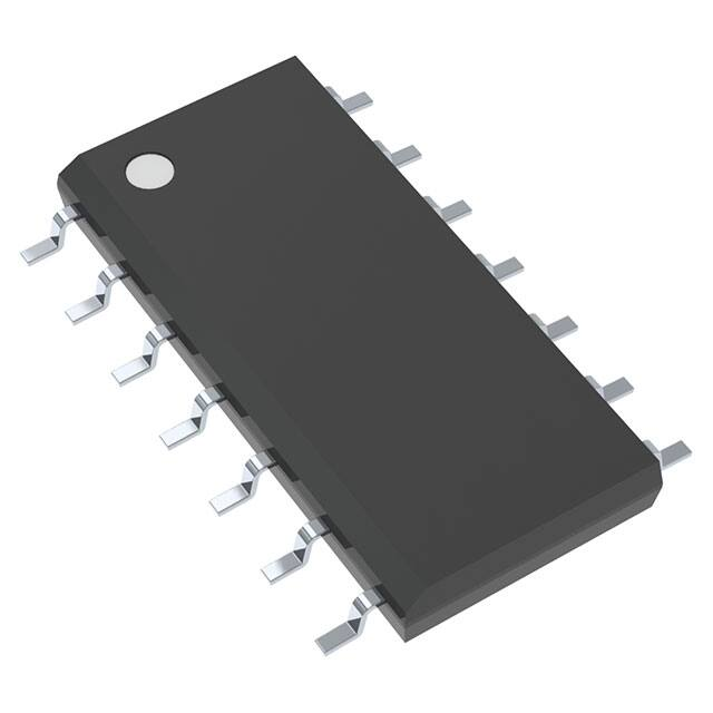
14-SOP
应用
标准半桥和全桥驱动器
PDP 能量恢复开关控制驱动器
1
开关电源
订购信息
器件编号
FAN7385M(1)
FAN7385MX(1)
封装
无铅
工作温度范围
14-SOP
是
-40°C ~ 125°C
包装方法
塑料管
卷带和卷盘
注:
1. 这些器件通过了 JESD22A-111 波峰焊测试。
© 2006 飞兆半导体公司
FAN7385 Rev. 1.0.2
www.fairchildsemi.com
FAN7385 双通道高侧栅极驱动 IC
2013 年 11 月
�FAN7385 双通道高侧栅极驱动 IC
应用电路图
VS
RBOOT
DBOOT1
Q3
FAN7385
D3
15V
IN1
IN2
1
VDD
2
NC
VB1
14
HO1
13
3
IN1
VS1
12
4
NC
NC
11
5
IN2
VB2
10
6
NC
HO2
9
7
GND
VS2
8
L1
D1
CBOOT1
To
Pannel
D2
Q4
D4
DBOOT2
Q1
Buffer IC
Q2
C1
CBOOT2
HVIC
FAN7380
FAN7382
C2
Energy Recovery
Sustain Driver
FAN7385 Rev.01
图 1. 浮动双向开关控制 PDP 应用
RBOOT1
VDC
DBOOT1
Full-Bridge Converter
15V
1
VDD
VB1
14
2
NC
HO1
13
3
IN1
VS1
12
CBOOT1
C1
4
NC
NC
11
5
IN2
VB2
10
6
NC
HO2
9
7
GND
VS2
8
Load
CBOOT2
Controller
RBOOT2
DBOOT2
L-CH Output
R-CH Output
FAN7385 Rev.01
图 2. 全桥电源应用
RBOOT
DBOOT
VDC
Q1
15V
VB1
1
VDD
2
NC
HO1
13
3
IN1
VS1
12
4
NC
NC
11
5
IN2
VB2
10
6
NC
HO2
9
7
GND
VS2
8
CBOOT
INPUT1
INPUT2
L
C
Vout
Q2
C1
Resonant Converter
14
Co
C2
FAN7385 Rev.01
图 3. 半桥 LCC 谐振转换器应用
© 2006 飞兆半导体公司
FAN7385 Rev.1.0.2
www.fairchildsemi.com
2
�VDD
DRIVER
R
R
S
13
HO1
12
VS1
10
VB2
9
HO2
8
VS2
Q
SCHMITT
TRIGGER INPUT
UVLO
5
NOISE
CANCELLER
R
S
DRIVER
7
PULSE
GENERATOR
500K
GND
NOISE
CANCELLER
3
500K
IN2
VB1
UVLO
1
PULSE
GENERATOR
IN1
14
R
Q
Pin 2, 4, 6 and 11 are not connection
FAN7385 Rev.01
图 4. 功能框图
© 2006 飞兆半导体公司
FAN7385 Rev.1.0.2
www.fairchildsemi.com
3
FAN7385 双通道高侧栅极驱动 IC
内部框图
�FAN7385 双通道高侧栅极驱动 IC
引脚配置
VDD
1
14
VB1
NC
2
13
HO1
IN1
3
12
VS1
NC
4
11
NC
IN2
5
10
VB2
NC
6
9
HO2
GND
7
8
VS2
FAN7385
FAN7385 Rev.00
图 5. 引脚配置 (俯视图)
引脚定义
引脚号
名称
说明
1
VDD
电源
2
NC
无连接
3
IN1
通道 1 控制输入
4
NC
无连接
5
IN2
通道 2 控制输入
6
NC
无连接
7
GND
接地
8
VS2
通道 2 浮动电源返回
通道 2 输出
9
HO2
10
VB2
通道 2 浮动电源
11
NC
无连接
12
VS1
通道 1 浮动电源返回
13
HO1
通道 1 输出
14
VB1
通道 1 浮动电源
© 2006 飞兆半导体公司
FAN7385 Rev.1.0.2
www.fairchildsemi.com
4
�应力超过绝对最大额定值,可能会损坏器件。在超出推荐的工作条件的情况下,该器件可能无法正常工作,所以不建议
让器件在这些条件下长期工作。此外,长期在高于推荐的工作条件下工作,会影响器件的可靠性。绝对最大额定值仅是
应力规格值。除非另有说明, TA= 25°C。
符号
参数
VS
高侧偏置电压 VS1、 VS2
最小值
最大值
单位
VB-25
VB+0.3
V
VB
高侧浮动电源电压 VB1、 VB2
-0.3
625
V
VHO
高侧浮动输出电压 HO1、 HO2
VS-0.3
VB+0.3
V
VDD
低侧和固定逻辑电源电压
-0.3
25
V
VIN
逻辑输入电压 (IN1、 IN2)
-0.3
VDD+0.3
V
VDD-25
VDD+0.3
V
允许的偏置电压变化速率
50
V/ns
功耗
1.0
W
θJA
结至环境热阻
110
°C/W
TJ
结温
150
°C
TS
存储温度
150
°C
GND
dVS/dt
PD(2)(3)(4)
逻辑地
注意:
2. 安装到 76.2 x 114.3 x 1.6 mm PCB 板 (FR-4 环氧玻璃材料)。
3. 参考以下标准:
JESD51-2: 集成电路热测试方法环境条件 - 自然对流
JESD51-3: 含铅表面贴装封装的低有效导热系数测试板
4. 在任何情况下,都不要超过 PD。
推荐工作条件
推荐的操作条件表明确了器件的真实工作条件。指定推荐的工作条件,以确保器件的最佳性能达到数据表中的规格。
飞兆半导体建议不要超过推荐工作条件,也不能按照绝对最大额定值进行设计。
符号
参数
条件
最小值
最大值
单位
V
VB
高侧浮动电源电压
VS+10
VS+20
VS
高侧浮动电源偏置电压
6-VDD
600
V
20
V
VDD
电源电压
10
VHO
高侧 (HO1、 HO2)输出电压
VS
VB
V
VIN
逻辑输入电压 (IN1、 IN2)
GND
VDD
V
TA
环境温度
-40
125
°C
© 2006 飞兆半导体公司
FAN7385 Rev.1.0.2
www.fairchildsemi.com
5
FAN7385 双通道高侧栅极驱动 IC
绝对最大额定值
�除非另有说明,VBIAS (VDD、VBS1、VBS2) = 15.0V、TA = 25°C。VIN 和 IIN 参数以 GND 作为基准。VO 和 IO 参数以 VS1
和 VS2 作为基准,适用于各自的输出 HO1 和 HO2。
符号
特性
电源电流部分
IQDD
VDD 静态电源电流
IPDD
条件
最小值 典型值 最大值 单位
VIN1= VIN2= 0 V 或 5 V
fIN1=fIN2=10kHz, rms value
VDD 工作电源电流
28
50
μA
35
70
μA
自举电源部分
VBSUV+ VBS1 和 VBS2 电源欠压正向阈值
VBS1= VBS2= 扫描
8.2
9.1
10.2
V
VBSUV-
VBS1 和 VBS2 电源欠压负向阈值
VBS1= VBS2= 扫描
7.6
8.5
9.6
V
VBSHYS
VBS1 和 VBS2 电源欠压锁定滞回电压回
差
VBS1= VBS2= 扫描
偏置电源漏电流
VB=VS=600V
IQBS1,2
VBS1 和 VBS2 静态电源电流
VIN1= 0 V 或 5 V
IPBS1,2
VBS1 和 VBS2 工作电源电流
fIN1= 10 kHz, rms 值
ILK
栅极驱动器输出部分
VOH
高电平输出电压, VBIAS-VO
VOL
低电平输出电压, VO
IO+
0.6
V
10
μA
50
85
μA
220
300
μA
30
mV
30
mV
IO= 0 mA (空载)
输出高电平短路脉冲电流
IO= 0 mA (空载)
VO= 0 V, VIN= 5 V, PW
很抱歉,暂时无法提供与“FAN7385MX”相匹配的价格&库存,您可以联系我们找货
免费人工找货- 国内价格
- 1+8.12160
- 10+7.31160
- 30+6.80400
- 100+6.28560
- 500+6.04800
- 1000+5.94000