FAN7391
High-Current, High & Low-Side, Gate-Drive IC
Features
Description
Floating Channels for Bootstrap Operation to +600 V
The FAN7391 is a monolithic high- and low-side gatedrive IC, which can drive high-speed MOSFETs and
IGBTs that operate up to +600 V. It has a buffered output
stage with all NMOS transistors designed for high pulse
current driving capability and minimum cross-conduction.
Typically 4.5 A / 4.5 A Sourcing / Sinking Current
Driving Capability
Common-Mode dv/dt Noise-Canceling Circuit
Built-in Under-Voltage Lockout for Both Channels
Built-in Advanced Input Filter
Matched Propagation Delay for Both Channels
Logic (VSS) and Power (COM) Ground ±5 V Offset
3.3 V and 5 V Input Logic Compatible
Output In-Phase with Input
High-voltage process and common-mode
noise-canceling techniques provide stable operation of
the high-side driver under high-dv/dt noise circumstances. An advanced level-shift circuit offers high-side
gate driver operation up to VS=-9.8 V (typical) for
VBS=15 V.
The advanced input filter of HIN provides protection
against short-pulsed input signals caused by noise.
Applications
The UVLO circuit prevents malfunction when VDD and
VBS are lower than the specified threshold voltage.
Plasma Display Panel (PDP) Sustain Driver
High-Intensity Discharge (HID) Lamp Ballast
Switching Mode Power Supply (SMPS)
The high-current and low-output voltage-drop feature
makes this device suitable for the PDP sustain pulse
driver, motor driver, switching mode power supply, and
high-power DC-DC converter applications.
Motor Driver
Related Resources
AN-6076 — Design and Application Guide of Boot-
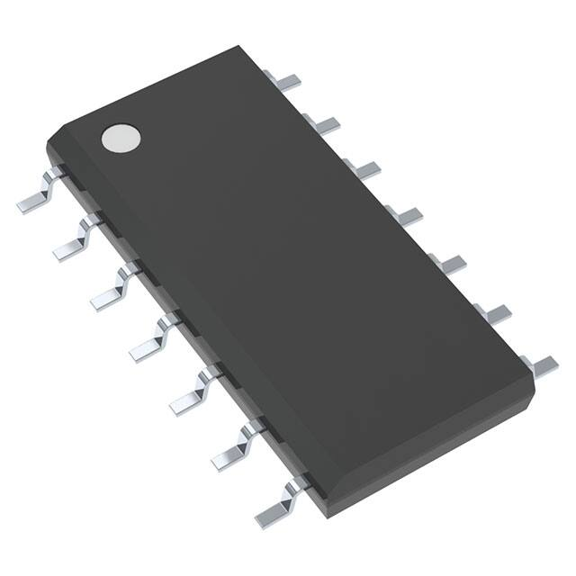
14-SOP
strap Circuit for High-Voltage Gate-Drive IC
AN-9052 — Design Guide for Selection of Bootstrap
Components
AN-8102 — Recommendations to Avoid Short Pulse
Width Issues in HVIC Gate Driver Applications
Ordering Information
Part Number
Package
Operating Temperature Range
Packing Method
FAN7391MX
14-SOP
-40C ~ 125C
Tape & Reel
© 2014 Semiconductor Components Industries, LLC.
FAN7391 Rev. 2
www.onsemi.com
FAN7391 — High-Current, High & Low Side, Gate-Drive IC
July 2017
�FAN7391 — High-Current, High & Low Side, Gate-Drive IC
Typical Application Circuit
Figure 1. Application Circuit for Half-Bridge
Internal Block Diagram
Figure 2. Functional Block Diagram
© 2014 Semiconductor Components Industries, LLC.
FAN7391 Rev. 2
www.onsemi.com
3
�FAN7391 — High-Current, High & Low Side, Gate-Drive IC
Pin Configurations
Figure 3. Pin Assignments (Top View)
Pin Definitions
14-Pin
Name
Description
1
HIN
Logic Input for High-Side Gate Driver Output
2
LIN
Logic Input for Low-Side Gate Driver Output
3
VSS
Logic Ground
5
COM
Low-Side Driver Return
6
LO
Low-Side Driver Output
7
VDD
Low-Side and Logic Part Supply Voltage
11
VS
High-Voltage Floating Supply Return
12
HO
High-Side Driver Output
13
VB
High-Side Floating Supply
4, 8, 9, 10, 14
NC
No Connect
© 2014 Semiconductor Components Industries, LLC.
FAN7391 Rev. 2
www.onsemi.com
4
�Stresses exceeding the absolute maximum ratings may damage the device. The device may not function or be operable above the recommended operating conditions and stressing the parts to these levels is not recommended. In addition, extended exposure to stresses above the recommended operating conditions may affect device reliability. The
absolute maximum ratings are stress ratings only. TA=25°C, unless otherwise specified.
Symbol
Characteristics
VS
High-Side Floating Supply Offset Voltage
VB
High-Side Floating Supply Voltage
Min.
Max.
Unit
VB-VSHUNT
VB+0.3
V
-0.3
625.0
V
VB+0.3
V
VHO
High-Side Floating Output Voltage, HO Pin
VS-0.3
VDD
Low-Side and Logic Fixed Supply Voltage
-0.3
VSHUNT
V
VLO
Low-Side Output Voltage, LO Pin
-0.3
VDD+0.3
V
VIN
Logic Input Voltage (HIN and LIN)
VSS-0.3
VDD+0.3
V
VSS
Logic Ground
VDD-25
VDD+0.3
V
Allowable Offset Voltage Slew Rate
50
V/ns
Power Dissipation
1.0
W
JA
Thermal Resistance, Junction-to-Ambient
110
C/W
TJ
Junction Temperature
+150
C
TSTG
Storage Temperature
+150
C
dVS/dt
PD(1)(2)(3)
Notes:
1. Mounted on 76.2 x 114.3 x 1.6 mm PCB (FR-4 glass epoxy material).
2. Refer to the following standards:
JESD51-2: Integral circuits thermal test method environmental conditions - natural convection; and
JESD51-3: Low effective thermal conductivity test board for leaded surface-mount packages.
3. Do not exceed PD maximum under any circumstances.
Recommended Operating Conditions
The Recommended Operating Conditions table defines the conditions for actual device operation. Recommended
operating conditions are specified to ensure optimal performance to the datasheet specifications. Fairchild does not
recommend exceeding them or designing to absolute maximum ratings.
Symbol
Parameter
Min.
Max.
Unit
VB
High-Side Floating Supply Voltage
VS+10
VS+20
V
VS
High-Side Floating Supply Offset Voltage
6-VDD
600
V
VHO
High-Side Output Voltage
VS
VB
V
VDD
Low-Side and Logic Supply Voltage
10
20
V
VLO
Low-Side Output Voltage
COM
VDD
V
VIN
Logic Input Voltage (HIN and LIN)
VSS
VDD
V
TA
Operating Ambient Temperature
-40
+125
C
Pulse Width of Logic Input for High-Side Gate Driver
100
PWHIN
© 2014 Semiconductor Components Industries, LLC.
FAN7391 Rev. 2
ns
www.onsemi.com
5
FAN7391 — High-Current, High & Low Side, Gate-Drive IC
Absolute Maximum Ratings
�VBIAS (VDD, VBS)=15.0 V, VS=VSS=COM, TA=25C, unless otherwise specified. The VIL, VIH, and IIN parameters are
referenced to VSS/COM and are applicable to the respective input signals HIN and LIN. The VO and IO parameters are
referenced to COM and VS is applicable to the respective output signals HO and LO.
Symbol
Characteristics
Condition
Min.
Typ.
Max. Unit
POWER SUPPLY SECTION (VDD AND VBS)
VDDUV+
VBSUV+
VDD and VBS Supply Under-Voltage
Positive-Going Threshold
8.0
8.8
9.8
VDDUVVBSUV-
VDD and VBS Supply Under-Voltage
Negative-Going Threshold
7.4
8.3
9.0
VDDUVH VDD and VBS Supply Under-Voltage
VBSUVH Lockout Hysteresis Voltage
V
0.5
ILK
Offset Supply Leakage Current
VB=VS=600 V
50
IQBS
Quiescent VBS Supply Current
VIN=0 V or 5 V
45
80
IQDD
Quiescent VDD Supply Current
VIN=0 V or 5 V
75
110
IPBS
Operating VBS Supply Current
fIN=20 kHz, rms value
530
640
IPDD
Operating VDD Supply Current
fIN=20 kHz, rms value
530
640
23
25
μA
μA
SHUNT REGULATOR SECTION
VSHUNT
VDD=Sweep or VBS=Sweep,
ISHUNT=5 mA
VDDand VBS Shunt Regulator Clamping
Voltage
21
V
LOGIC INPUT SECTION (HIN, LIN)
VIH
Logic "1" Input Voltage
VIL
Logic "0" Input Voltage
IIN+
Logic "1" Input Bias Current
VIN=5 V
25
50
IIN-
Logic "0" Input Bias Current
VIN=0 V
1.0
2.0
RIN
Input Pull-Down Resistance
2.5
1.2
100
200
V
μA
k
GATE DRIVER OUTPUT SECTION (HO, LO)
VOH
High-Level Output Voltage, VBIAS-VO
No Load
1.0
V
VOL
Low-Level Output Voltage, VO
No Load
35
mV
IO+
Output High, Short-Circuit Pulsed Current(4) VO=0 V, VIN=5 V,PW
很抱歉,暂时无法提供与“FAN7391MX”相匹配的价格&库存,您可以联系我们找货
免费人工找货- 国内价格
- 625+21.13176
- 1250+20.49444