Is Now Part of
To learn more about ON Semiconductor, please visit our website at
www.onsemi.com
Please note: As part of the Fairchild Semiconductor integration, some of the Fairchild orderable part numbers
will need to change in order to meet ON Semiconductor’s system requirements. Since the ON Semiconductor
product management systems do not have the ability to manage part nomenclature that utilizes an underscore
(_), the underscore (_) in the Fairchild part numbers will be changed to a dash (-). This document may contain
device numbers with an underscore (_). Please check the ON Semiconductor website to verify the updated
device numbers. The most current and up-to-date ordering information can be found at www.onsemi.com. Please
email any questions regarding the system integration to Fairchild_questions@onsemi.com.
ON Semiconductor and the ON Semiconductor logo are trademarks of Semiconductor Components Industries, LLC dba ON Semiconductor or its subsidiaries in the United States and/or other countries. ON Semiconductor owns the rights to a number
of patents, trademarks, copyrights, trade secrets, and other intellectual property. A listing of ON Semiconductor’s product/patent coverage may be accessed at www.onsemi.com/site/pdf/Patent-Marking.pdf. ON Semiconductor reserves the right
to make changes without further notice to any products herein. ON Semiconductor makes no warranty, representation or guarantee regarding the suitability of its products for any particular purpose, nor does ON Semiconductor assume any liability
arising out of the application or use of any product or circuit, and specifically disclaims any and all liability, including without limitation special, consequential or incidental damages. Buyer is responsible for its products and applications using ON
Semiconductor products, including compliance with all laws, regulations and safety requirements or standards, regardless of any support or applications information provided by ON Semiconductor. “Typical” parameters which may be provided in ON
Semiconductor data sheets and/or specifications can and do vary in different applications and actual performance may vary over time. All operating parameters, including “Typicals” must be validated for each customer application by customer’s
technical experts. ON Semiconductor does not convey any license under its patent rights nor the rights of others. ON Semiconductor products are not designed, intended, or authorized for use as a critical component in life support systems or any FDA
Class 3 medical devices or medical devices with a same or similar classification in a foreign jurisdiction or any devices intended for implantation in the human body. Should Buyer purchase or use ON Semiconductor products for any such unintended
or unauthorized application, Buyer shall indemnify and hold ON Semiconductor and its officers, employees, subsidiaries, affiliates, and distributors harmless against all claims, costs, damages, and expenses, and reasonable attorney fees arising out
of, directly or indirectly, any claim of personal injury or death associated with such unintended or unauthorized use, even if such claim alleges that ON Semiconductor was negligent regarding the design or manufacture of the part. ON Semiconductor
is an Equal Opportunity/Affirmative Action Employer. This literature is subject to all applicable copyright laws and is not for resale in any manner.
�FAN73933
半桥栅极驱动 IC
特性
说明
浮动通道可实现高达 +600V 的自举运行
FAN73933 是一款具有关断和可编程死区控制功能的半桥
栅极驱动 IC,可驱动工作电压高达 +600V 的高速
MOSFET 和绝缘栅双极型晶体管 (IGBT)。它具有缓冲输
出级,且所有 NMOS 晶体管设计为具有高脉冲电流驱动
能力和最低减少交叠导通。
2.5A/2.5A 的典型源电流 / 灌电流驱动能力
将容许负 VS 摆幅扩展至 -9.8V,用于 VBS=15V 时的信
号传播
输出与输入信号同相
兼容 3.3V 和 5V 逻辑输入电平
适用于两个通道的匹配传播延迟
两个通道均内置欠压闭锁 (UVLO) 功能
内置共模 dv/dt 噪声消除电路
飞兆半导体的高压工艺和共模噪声消除技术,即使在较高
dv/dt 噪声环境中,也能够保证高侧驱动器工作稳定。先
进的电平转换电路,能使高侧栅极驱动器的工作电压在
VBS=15V 时 VS 达到 -9.8V (典型值)。
可编程死区时间控制功能
UVLO 电路可防止驱动电路当 VDD 和 VBS 低于指定的阈
RDT=0Ω 时,内部最小死区时间为 220ns
值电压时发生故障。
应用
高电流和低输出压降的特性,使得该器件适合于不同的半
桥和全桥逆变器、电机驱动逆变器、开关电源、感应加热,
以及大功率 DC-DC 转换器等应用。
高速功率 MOSFET 和 IGBT 栅极驱动器
感应加热
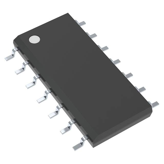
14-SOP
大功率 DC-DC 转换器
同步降压转换器
电机驱动逆变器
订购信息
器件编号
封装
工作温度范围
FAN73933M
14 引脚小外形集成电路 (SOIC)、
非 JEDEC、 150 英寸窄体、
225SOP
-40°C 至 +125°C
FAN73933MX
Eco
状态
包装方法
塑料管
RoHS
卷带和卷盘
对于飞兆公司的 Eco 状态定义,请访问:http://www.fairchildsemi.com/company/green/rohs_green.html.
© 2009 飞兆半导体公司
FAN73933 • Rev. 1.0.0
www.fairchildsemi.com
FAN73933 — 半桥栅极驱动器
2013 年 10 月
�FAN73933 — 半桥栅极驱动器
应用电路图
Up to 600V
+15V
RBOOT DBOOT
FAN73933
Controller
HIN
1 HIN
NC 14
LIN
2 LIN
VB 13
3
HO 12
VSS
R1
R2
CBOOT
RDT
4 DT
VS 11
5 COM
NC 10
6 LO
NC 9
7 VDD
NC 8
Load
R3
R4
图 1. 典型应用电路
内部框图
13 VB
UVLO
NOISE
CANCELLER
R
DRIVER
250K
PULSE
GENERATOR
HS(ON/OFF)
HIN 1
R
S
Q
11 VS
SCHMITT
TRIGGER INPUT
LIN
2
7 VDD
250K
SHOOT THOUGH
PREVENTION
UVLO
4
VSS
3
DEAD-TIME
{ DTMIN=220ns }
LS(ON/OFF)
VSS/COM
LEVEL
SHIFT
DELAY
DRIVER
RDTINT
DT
12 HO
6 LO
5
COM
Pin 8, 9, 10 and 14 are no connection
图 2. 功能框图
© 2009 飞兆半导体公司
FAN73933 • Rev. 1.0.0
www.fairchildsemi.com
2
�FAN73933 — 半桥栅极驱动器
引脚布局
1
14
NC
LIN
2
13
VB
VSS
3
12
HO
DT
4
11
VS
COM
5
10
NC
LO
6
9
NC
VDD
7
8
NC
FAN73933
HIN
图 3. 引脚布局 (顶视图)
引脚定义
引脚号
名称
1
HIN
说明
高侧栅极驱动器输出的逻辑输入
2
LIN
低侧栅极驱动器输出的逻辑输入
3
VSS
逻辑地
外接电阻进行死区控制 (参考 VSS)
4
DT
5
COM
6
LO
低侧栅极驱动输出
7
VDD
电源电压
8
NC
无连接
9
NC
无连接
10
NC
无连接
11
VS
高压浮地
12
HO
高侧驱动输出
13
VB
高侧浮动电源
14
NC
无连接
© 2009 飞兆半导体公司
FAN73933 • Rev. 1.0.0
接地
www.fairchildsemi.com
3
�应力超过绝对最大额定值,可能会损坏器件。在超出推荐的工作条件的情况下,该器件可能无法正常工作,所以不建议
让器件在这些条件下长期工作。此外,在远高于推荐的工作条件下工作,会影响器件的可靠性。绝对最大额定值仅是应
力规格值。除非另有说明, TA=25°C。
符号
特性
最小值
最大值
单位
VB
高侧浮动电源电压
-0.3
625.0
V
VS
高侧浮动偏置电压
VB-25.0
VB+0.3
V
VHO
高侧浮动输出电压
VS-0.3
VB+0.3
V
VLO
低侧输出电压
-0.3
VDD+0.3
V
VDD
低侧和固定逻辑电源电压
-0.3
25.0
V
VIN
逻辑输入电压 (HIN, LIN)
-0.3
VDD+0.3
V
DT
可编程死区时间引脚电压
-0.3
VDD+0.3
V
VSS
逻辑地
VDD-25
VDD+0.3
V
± 50
V/ns
dVS/dt
PD
θJA
TJ
TSTG
允许的偏置电压变化速率
功率耗散 (1, 2, 3)
1
W
热阻
110
°C/W
结温
+150
°C
+150
°C
-55
存储温度
注意:
1 安装到 76.2 x 114.3 x 1.6mm PCB 板 (FR-4 环氧玻璃材料 )。
2 参照下列标准:
JESD51-2:集成电路热测试方法环境条件 – 自然通风;
JESD51-3:含铅表面贴装封装的低有效导热系数测试板。
3 在任何情况下,都不要超过 PD。
推荐工作条件
推荐的操作条件表定义了器件的真实工作条件。指定推荐的工作条件,以确保器件的最佳性能达到数据表中的规格。
飞兆不建议超出额定或依照绝对最大额定值进行设计。
符号
VB
VS
参数
最小值
最大值
单位
高侧浮动电源电压
VS+10
VS+20
V
高侧浮动电源偏置电压
6-VDD
600
V
VS
VB
V
VHO
高侧输出电压
VDD
低侧和固定逻辑电源电压
10
20
V
低侧输出电压
COM
VDD
V
逻辑输入电压 (HIN, LIN)
VSS
VDD
V
DT
可编程死区时间引脚电压
VSS
VDD
V
VSS
逻辑地
-5
+5
V
工作环境温度
-40
+125
°C
VLO
VIN
TA
© 2009 飞兆半导体公司
FAN73933 • Rev. 1.0.0
www.fairchildsemi.com
4
FAN73933 — 半桥栅极驱动器
绝对最大额定值
�VBIAS(VDD, VBS)=15.0V, VSS=COM=0V, DT=VSS 且 TA = 25°C,除非另有说明参数 VIN 和 IIN 以 o VSS/COM 为参考,
并适用于相应的输入引脚:HIN 和 LIN。参数 VO 和 IO 以 COM 为参考,并适用于相应的输出引脚:HO 和 LO。
符号
特性
测试条件
最小值 典型值 最大值 单位
电源部分
IQDD
VDD 电源静态电流
VIN=0V 或 5V
0.9
1.5
mA
IQBS
VBS 静态电源电流
VIN=0V 或 5V
50
100
μA
IPDD
VDD 电源工作电流
fIN=20KHz,无负载
1.3
1.9
mA
IPBS
VBS 电源静态电流
CL=1nF, fIN=20KHz, rms
450
800
μA
偏置漏电流
VB=VS=600V
10
μA
ILK
自举电源部分
VDDUV+
VBSUV+
VDD 和 VBS 电源欠压正向 (电压从高到低) V =0V, V =V =Sweep
IN
DD
BS
阈值电压
8.0
9.0
10
V
VDDUVVBSUV-
VDD 和 VBS 电源欠压负向 (电压从低到高) V =0V, V =V =Sweep
IN
DD
BS
阈值电压
7.4
8.4
9.4
V
VDDUVH
VBSUVH VDD 和 VBS 电源欠压锁定滞回电压回差
VIN=0V, VDD=VBS=Sweep
0.6
V
输入逻辑部分
VIH
逻辑 “1” 输入电压适用于 HO,逻辑 “0” 适用
于 LO
VIL
逻辑 “0” 输入电压适用于 HO,逻辑 “1” 适用
于 LO
IIN+
逻辑输入高偏置电流
VIN=5V
IIN-
逻辑输入低偏置电流
VIN=0V
RIN
逻辑输入下拉电阻
2.5
V
20
100
0.8
V
50
μA
2
μA
250
KΩ
栅级驱动输出部分
VOH
高电平输出电压 (VBIAS - VO)
无负载
1.5
V
VOL
低电平输出电压
无负载
100
mV
IO+
输出高电平短路脉冲电流 (4)
VHO=0V, VIN=5V, PW
≤10µs
2.0
2.5
A
IO-
输出低电平短路脉冲电流 (4)
VHO=15V,VIN=0V, PW
≤10µs
2.0
2.5
A
VS
允许的做为输入信号传播到 HO 的 VS 负电
压
-9.8
-7.0
V
注:
4. 这些参数由设计者确定。
© 2009 飞兆半导体公司
FAN73933 • Rev. 1.0.0
www.fairchildsemi.com
5
FAN73933 — 半桥栅极驱动器
电气特性
�VBIAS(VDD, VBS)=15.0V, VSS=COM=0V, CL=1000pF, DT=VSS 且 TA=25°C,除非另有说明。
符号
tON
参数
(5)
工作条件
最小值 典型值 最大值 单位
VS=0V, RDT=0Ω
160
230
ns
VS=0V
160
230
ns
延时匹配, HO 与 LO 导通
0
50
ns
延时匹配, HO 与 LO 关断
0
50
ns
导通传播延时
tOFF
关断传播延时
MtON
MtOFF
开通上升时间
VS=0V
40
60
ns
tF
关断下降时间
VS=0V
20
35
ns
DT
死区时间:LO 关断至 HO 导通,以及
HO 关断至 LO 导通
RDT=0Ω
170
220
270
ns
RDT=300KΩ
400
500
600
ns
tR
MDT
死区时间匹配 =|DTLO-HO - DTHO-LO|
RDT=0Ω
0
50
ns
RDT=300KΩ
0
100
ns
注:
5 导通传播延时不包括死区时间
© 2009 飞兆半导体公司
FAN73933 • Rev. 1.0.0
www.fairchildsemi.com
6
FAN73933 — 半桥栅极驱动器
动态电气特性
�230
210
210
190
190
170
170
tOFF [ns]
tON [ns]
230
150
130
130
High-Side
Low-Side
110
90
-40
150
-20
0
20
40
60
80
100
High-Side
Low-Side
110
90
-40
120
-20
0
图 4. 导通传播延时与温度的关系
60
40
60
80
100
120
图 5. 关断传播延时与温度的关系
High-Side
Low-Side
50
High-Side
Low-Side
30
tF [ns]
40
tR [ns]
20
Temperature [°C]
Temperature [°C]
30
20
20
10
10
0
-40
-20
0
20
40
60
80
100
0
-40
120
-20
0
图 6. 导通上升时间与温度的关系
40
60
80
100
120
图 7. 关断下降时间与温度的关系
300
50
25
250
MDT [ns]
DT [ns]
20
Temperature [°C]
Temperature [°C]
0
200
150
-40
-25
DT1
DT2
(RDT=0Ω)
-20
0
20
40
60
80
100
(RDT=0Ω)
-50
-40
120
Temperature [°C]
0
20
40
60
80
100
120
Temperature [°C]
图 8. 死区时间 (RDT=0W) 与温度的关系
© 2009 飞兆半导体公司
FAN73933 • Rev. 1.0.0
-20
图 9. 死区时间匹配 (RDT=0W)
与温度的关系
www.fairchildsemi.com
7
FAN73933 — 半桥栅极驱动器
典型特性
�FAN73933 — 半桥栅极驱动器
典型特性 (续)
50
600
575
40
MDT [ns]
DT [ns]
550
525
500
30
20
475
450
400
-40
10
DT1
DT2
(RDT=300KΩ)
425
-20
0
20
40
60
80
100
0
-40
120
(RDT=300KΩ)
-20
0
20
40
60
80
100
120
Temperature [°C]
Temperature [°C]
图 10. 死区时间 (RDT=300KW) 与温度的关系
图 11. 死区时间匹配 (RDT=300KW)
与温度的关系
50
600
30
500
20
DT [ns]
Delay Matching [ns]
40
10
0
-10
300
-20
MTON
-30
200
MTOFF
-40
-50
-40
400
(RDT=0Ω)
-20
0
20
40
60
80
100
100
0
120
50
100
Temperature [°C]
图 12. 延迟匹配与温度的关系
200
250
300
图 13. 死区时间与 RDT
1500
100
1300
80
IQBS [μA]
IQDD [μA]
150
RDT [KΩ]
1100
900
60
40
700
20
500
300
-40
-20
0
20
40
60
80
100
0
-40
120
图 14. 静态 VDD 电源电流与温度的关系
© 2009 飞兆半导体公司
FAN73933 • Rev. 1.0.0
-20
0
20
40
60
80
100
120
Temperature [°C]
Temperature [°C]
图 15. 静态 VBS 电源电流与温度的关系
www.fairchildsemi.com
8
�FAN73933 — 半桥栅极驱动器
典型特性 (续)
800
1900
700
1700
600
IPBS [μA]
IPDD [μA]
1500
1300
1100
400
300
900
700
-40
500
200
-20
0
20
40
60
80
100
100
-40
120
-20
0
10.0
9.5
9.5
9.0
9.0
8.5
60
80
100
120
8.5
8.0
-20
0
20
40
60
80
100
7.5
-40
120
-20
0
Temperature [°C]
20
40
60
80
100
120
Temperature [°C]
图 18.VDD UVLO+ 与温度的关系
图 19.VDD UVLO- 与温度的关系
10.0
9.5
9.5
9.0
VBSUV- [V]
VBSUV+ [V]
40
图 17. 工作时 VBS 电源电流与温度的关系
VDDUV- [V]
VDDUV+ [V]
图 16. 工作时 VDD 电源电流与温度的关系
8.0
-40
20
Temperature [°C]
Temperature [°C]
9.0
8.5
8.0
8.5
8.0
-40
-20
0
20
40
60
80
100
7.5
-40
120
图 20.VBS UVLO+ 与温度的关系
© 2009 飞兆半导体公司
FAN73933 • Rev. 1.0.0
-20
0
20
40
60
80
100
120
Temperature [°C]
Temperature [°C]
图 21.VBS UVLO- 与温度的关系
www.fairchildsemi.com
9
�0.4
2.0
High-Side
Low-Side
High-Side
Low-Side
0.2
VOL [V]
VOH [V]
1.5
1.0
0.0
-0.2
0.5
0.0
-40
-20
0
20
40
60
80
100
-0.4
-40
120
-20
0
图 22. 高电平输出电压与温度的关系
3.0
80
100
120
High-Side
Low-Side
2.5
VIH [V]
VIH [V]
60
3.0
High-Side
Low-Side
2.0
1.5
2.0
1.5
-20
0
20
40
60
80
100
1.0
-40
120
Temperature [°C]
-20
0
20
40
60
80
100
120
Temperature [°C]
图 24. 逻辑高电平输入电压与温度的关系
图 25. 逻辑低电平输入电压与温度的关系
-7
50
High-Side
Low-Side
-8
40
-9
VS [V]
IIN+ [μA]
40
图 23. 低电平输出电压与温度的关系
2.5
1.0
-40
20
Temperature [°C]
Temperature [°C]
30
20
-11
10
0
-40
-10
-12
-20
0
20
40
60
80
100
-13
-40
120
0
20
40
60
80
100
120
图 27. 容许的负 VS 电压与温度的关系
图 26. 逻辑输入高电平偏置电流与温度的关系
© 2009 飞兆半导体公司
FAN73933 • Rev. 1.0.0
-20
Temperature [°C]
Temperature [°C]
www.fairchildsemi.com
10
FAN73933 — 半桥栅极驱动器
典型特性 (续)
�FAN73933 — 半桥栅极驱动器
230
230
210
210
190
190
170
170
tOFF [ns]
tON [ns]
典型特性 (续)
150
130
130
High-Side
Low-Side
110
90
10
150
12
14
16
18
High-Side
Low-Side
110
90
10
20
12
Supply Voltage [V]
图 28. 导通传播延迟与电源电压的关系
60
20
High-Side
Low-Side
30
25
tF [ns]
tR [ns]
18
35
40
30
20
15
20
10
10
5
0
10
12
14
16
18
0
10
20
12
Supply Voltage [V]
14
16
18
20
18
20
Supply Voltage [V]
图 30. 导通上升时间与电源电压的关系
图 31. 关断下降时间
与电源电压的关系
1500
100
1300
80
IQBS [μA]
IQDD [μA]
16
图 29. 关断传播延迟与电源电压的关系
High-Side
Low-Side
50
14
Supply Voltage [V]
1100
900
60
40
700
20
500
300
10
12
14
16
18
0
10
20
图 32. 静态 VDD 电源电流与电源电压的关系
© 2009 飞兆半导体公司
FAN73933 • Rev. 1.0.0
12
14
16
Supply Voltage [V]
Supply Voltage [V]
图 33. 静态 VBS 电源电流与电源电压的关系
www.fairchildsemi.com
11
�0.4
2.0
High-Side
Low-Side
High-Side
Low-Side
0.2
VOL [V]
VOH [V]
1.5
1.0
-0.2
0.5
0.0
10
12
14
16
18
-0.4
10
20
12
14
16
18
20
Supply Voltage [V]
Supply Voltage [V]
图 34. 高电平输出电压与电源电压的关系
© 2009 飞兆半导体公司
FAN73933 • Rev. 1.0.0
0.0
图 35. 低电平输出电压
与电源电压的关系
www.fairchildsemi.com
12
FAN73933 — 半桥栅极驱动器
典型特性 (续)
�FAN73933 — 半桥栅极驱动器
开关时间定义
1
HIN
NC 14
LIN
2
LIN
VB 13
3
VSS
LO
FAN73933
HIN
+15V
HO 12
HO
1nF
4
DT
VS 11
5
COM
6
LO
NC
9
7
VDD
NC
8
10μF 100nF
NC 10
1nF
+15V
10μF
100nF
图 36. 开关时间测试电路
LIN
HIN
Shoot Though
Prevent
LO
Shoot Though
Prevent
HO
DT
DT
DT
DT
图 37. 输入 / 输出时序图
LIN
50%
50%
More than dead-time
HIN
50%
More than dead-time
50%
50%
tOFF
tOFF
90%
90%
tON
LO
10%
tOFF
90%
tON
HO
10%
图 38. 开关时间波形定义
© 2009 飞兆半导体公司
FAN73933 • Rev. 1.0.0
www.fairchildsemi.com
13
�瞬变 VS 负电压
图 41. 和图 42. 显示了同一逆变桥中,高侧开关 Q1 和低
侧续流二极管 D3 间的负载电流换流。逆变电路中从裸片
引脚绑定到 PCB 走线的寄生电感对于每个 IGBT 的 就是
LC 和 LE。当高侧开关 Q1 和低侧开关 Q4 导通时,由于
负载电流从 Q1 流向 Q4, VS1 节点电压低于 DC+ 电压
(跟电路的电源开关和寄生电感相关的电压降有关)如图
图 41. 所示;当高侧开关 Q1 关断而 Q4 仍然导通时,由
于 VS1 连有感性负载,负载电流通过低侧续流二极管 D3
续流,如图图 42. 所示。电流从地 (连接至栅极驱动器的
COM 引脚)流向负载,且负电压出现在高侧开关器件的
发射极。
自举式电路具有简单和低成本的优点,但是,它也有一些
局限。此电路的最大难题是,在半桥应用中,高侧的开关
器件关断时在其发射极存在负电压。
如果高侧开关 Q1 关断,同时负载电流流向电感负载;从
高侧开关 Q1 至二极管 D3 (与同一逆变器桥的低侧开关
并联)出现电流转移。然后,负电压出现在高侧开关器件
的发射极,在续流二极管开始箝位前,负载电流突然流向
低侧续流二极管 D3,如图 39. 所示:
DC+ Bus
Q2
Q1
D1
在此情况下,栅极驱动器的 COM 引脚电势高于 VS 引脚,
因为电压降与续流二级管 D3、寄生元件 LC3 和 LE3 相关。
D2
iLOAD
ifreewheeling
DC+ Bus
Load
VS1
VS2
LC1
LC2
VLC1
Q2
Q1
D1
Q4
Q3
D3
D2
iLOAD
D4
LE1
VLE1
ifreewheeling
LE2
Load
VS1
LC3
VS2
VLC4
Q4
Q3
图 39. 半桥应用电路
D3
此负电压给栅极驱动器输出时带来麻烦。很可能产生自举
电容过压的情况,输入信号丢失以及闭锁问题,因为它直
接影响栅极驱动器的电源 VS 引脚,如图图 40. 所示。此
负尖峰电压称为 “ 瞬变 VS 负电压 ”。
LC4
D4
LE3
VLE4
LE4
图 41. Q1 和 Q4 导通
DC+ Bus
Q1
GND
LC2
LC1
Q2
Q1
D1
D2
iLOAD
ifreewheeling
LE1
VS
LC3
GND
LE2
Load
VS1
VLC3
VS2
VLC4
Freewheeling
D3
LE3
LC4
Q4
Q3
VLE3
D4
VLE4
LE4
图 40.Q1 关断期间的 VS 波形
图 42.Q1 关断且 D3 导通
© 2009 飞兆半导体公司
FAN73933 • Rev. 1.0.0
www.fairchildsemi.com
14
FAN73933 — 半桥栅极驱动器
应用信息
�元件布置
建议选择如下所示元件:
在 VDD 和 VSS 引脚之间放置旁路电容。1µF 陶瓷电容
-100
适用于大多数应用。此元件应尽可能靠近引脚放置,
以减少寄生元件。
VDD 和 COM 之间的旁路电容同时支持低侧驱动器和自
举电容的再充电。建议该电容值至少是自举电容的十
倍以上。
在量化自举阻抗和初次自举充电时的电流时,必须考
虑自举电阻 RBOOT。如果电阻需要与自举二极管并
联,请确认 VB 不会下降至低于 COM (接地)。通常
建议采用 5 ~ 10Ω,这可增加 VBS 时间常量。如果自
举电阻和二极管间的电压降太大或电路拓扑不能提供
足够的充电时间,我们可以使用一个快速恢复或超快
恢复二极管。
自举电容 CBOOT 使用一个低 ESR 电容,比如陶瓷电
容。
-90
-80
-70
VS [V]
-60
-50
-40
-30
-20
-10
0
0
100
200
300
400
500
600
700
800
900 1000
强烈建议如下布置元件:
Pulse Width [ns]
布置元件连接到浮动电压引脚 (VB 和 VS) ,靠近器件和
图 43. 瞬变 VS 负电压特性
FAN73933 各自的高压部分。此封装中的 NC (非连
接)引脚应最大化高压和低压引脚之间的距离,如
(see 图 3.) 所示。
旁路电容和栅极电阻的布局和布线,应尽可能靠近栅
极驱动 IC。
使自举二极管 DBOOT 尽可能靠近自举电容 CBOOT。
自举二极管必须使用有较低的正向压降和开关时间很
快的的快恢或超快恢复二极管。
即使所示 FAN73933 能够处理这些负极性 VS 瞬变情况,
仍然强烈建议电路设计人员通过谨慎处理电路板布局,最
大限度地减小寄生参数,从而尽可能限制该 瞬变 VS 负电
压。负性 VS 电压的振幅与开关器件的寄生电感、关断速
度、 di/dt 成正比。
一般准则
印刷电路板布局
为了最大限度地减少寄生元件,建议如下电路板布局:
开关之间的走线没有回路或偏差。
避免互连链路。它会显著增加电感。
降低封装体距离 PCB 板的高度,以减少引脚电感效应。
考虑所有功率开关的配合放置,以减少走线长度。
为了最大限度地减少噪声耦合,接地层不应置于高压
浮置侧下方或附近。
为了减少 EM 耦合及改善电源开关导通 / 关断性能,必
须尽可能减少栅极驱动环路。
© 2009 飞兆半导体公司
FAN73933 • Rev. 1.0.0
www.fairchildsemi.com
15
FAN73933 — 半桥栅极驱动器
FAN73933 具有负极性 VS 瞬变性能曲线,如图 43. 所示
�8.76
8.36
0.65
A
7.62
14
8
B
5.60
6.00
4.15
3.75
B
1.70
B
#1
1.27
PIN ONE
INDICATOR
(0.27)
7
#1
1.27
TOP VIEW
0.51
0.36
0.20
C B A
LAND PATTERN RECOMMENDATION
SEE DETAIL A
1.80 MAX
1.65
1.45
(R0.20)
C
1.27
SIDE VIEW
0.30
0.15
B
0.05MIN
END VIEW
0.10 MAX C
NOTES:
A) THIS DRAWING COMPLIES WITH JEDEC MS-012
EXCEPT AS NOTED.
B) THIS DIMENSION IS OUTSIDE THE JEDEC MS-012 VALUE.
C) ALL DIMENSIONS ARE IN MILLIMETERS.
D) DIMENSIONS ARE EXCLUSIVE OF BURRS, MOLD FLASH,
AND TIE BAR EXTRUSIONS.
E) LANDPATTERN STANDARD: SOIC127P600X145-14M
F) DRAWING FILE NAME AND REVISION : M14CREV1
8°
GAGE
PLANE
(R0.10)
0.90
0.50
0.36
SEATING
PLANE
DETAIL A
图 44.14 引脚、小外形集成电路 (SOIC)、非 JEDEC、 150 英寸窄体、 225SOP
封装图纸是作为一项服务而提供给考虑选用飞兆半导体产品的客户。具体参数可能会有变化,且不会做出相应通知。请注意图纸上的版
本和 / 或日期,并联系飞兆半导体代表核实或获得最新版本。封装规格并不超出飞兆公司全球范围内的条款与条件,尤其指保修,保修
涵盖飞兆半导体的全部产品。
随时访问飞兆半导体在线封装网页,可以获得最新的封装图:
http://www.fairchildsemi.com/packaging/。
© 2009 飞兆半导体公司
FAN73933 • Rev. 1.0.0
www.fairchildsemi.com
16
FAN73933 — 半桥栅极驱动器
物理尺寸
�FAN73933 — 半桥栅极驱动器
© 2009 飞兆半导体公司
FAN73933 • Rev. 1.0.0
www.fairchildsemi.com
17
�ON Semiconductor and
are trademarks of Semiconductor Components Industries, LLC dba ON Semiconductor or its subsidiaries in the United States and/or other countries.
ON Semiconductor owns the rights to a number of patents, trademarks, copyrights, trade secrets, and other intellectual property. A listing of ON Semiconductor’s product/patent
coverage may be accessed at www.onsemi.com/site/pdf/Patent−Marking.pdf. ON Semiconductor reserves the right to make changes without further notice to any products herein.
ON Semiconductor makes no warranty, representation or guarantee regarding the suitability of its products for any particular purpose, nor does ON Semiconductor assume any liability
arising out of the application or use of any product or circuit, and specifically disclaims any and all liability, including without limitation special, consequential or incidental damages.
Buyer is responsible for its products and applications using ON Semiconductor products, including compliance with all laws, regulations and safety requirements or standards,
regardless of any support or applications information provided by ON Semiconductor. “Typical” parameters which may be provided in ON Semiconductor data sheets and/or
specifications can and do vary in different applications and actual performance may vary over time. All operating parameters, including “Typicals” must be validated for each customer
application by customer’s technical experts. ON Semiconductor does not convey any license under its patent rights nor the rights of others. ON Semiconductor products are not
designed, intended, or authorized for use as a critical component in life support systems or any FDA Class 3 medical devices or medical devices with a same or similar classification
in a foreign jurisdiction or any devices intended for implantation in the human body. Should Buyer purchase or use ON Semiconductor products for any such unintended or unauthorized
application, Buyer shall indemnify and hold ON Semiconductor and its officers, employees, subsidiaries, affiliates, and distributors harmless against all claims, costs, damages, and
expenses, and reasonable attorney fees arising out of, directly or indirectly, any claim of personal injury or death associated with such unintended or unauthorized use, even if such
claim alleges that ON Semiconductor was negligent regarding the design or manufacture of the part. ON Semiconductor is an Equal Opportunity/Affirmative Action Employer. This
literature is subject to all applicable copyright laws and is not for resale in any manner.
PUBLICATION ORDERING INFORMATION
LITERATURE FULFILLMENT:
Literature Distribution Center for ON Semiconductor
19521 E. 32nd Pkwy, Aurora, Colorado 80011 USA
Phone: 303−675−2175 or 800−344−3860 Toll Free USA/Canada
Fax: 303−675−2176 or 800−344−3867 Toll Free USA/Canada
Email: orderlit@onsemi.com
© Semiconductor Components Industries, LLC
N. American Technical Support: 800−282−9855 Toll Free
USA/Canada
Europe, Middle East and Africa Technical Support:
Phone: 421 33 790 2910
Japan Customer Focus Center
Phone: 81−3−5817−1050
www.onsemi.com
1
ON Semiconductor Website: www.onsemi.com
Order Literature: http://www.onsemi.com/orderlit
For additional information, please contact your local
Sales Representative
www.onsemi.com
�