ON Semiconductor
Is Now
To learn more about onsemi™, please visit our website at
www.onsemi.com
onsemi and and other names, marks, and brands are registered and/or common law trademarks of Semiconductor Components Industries, LLC dba “onsemi” or its affiliates and/or
subsidiaries in the United States and/or other countries. onsemi owns the rights to a number of patents, trademarks, copyrights, trade secrets, and other intellectual property. A listing of onsemi
product/patent coverage may be accessed at www.onsemi.com/site/pdf/Patent-Marking.pdf. onsemi reserves the right to make changes at any time to any products or information herein, without
notice. The information herein is provided “as-is” and onsemi makes no warranty, representation or guarantee regarding the accuracy of the information, product features, availability, functionality,
or suitability of its products for any particular purpose, nor does onsemi assume any liability arising out of the application or use of any product or circuit, and specifically disclaims any and all
liability, including without limitation special, consequential or incidental damages. Buyer is responsible for its products and applications using onsemi products, including compliance with all laws,
regulations and safety requirements or standards, regardless of any support or applications information provided by onsemi. “Typical” parameters which may be provided in onsemi data sheets and/
or specifications can and do vary in different applications and actual performance may vary over time. All operating parameters, including “Typicals” must be validated for each customer application
by customer’s technical experts. onsemi does not convey any license under any of its intellectual property rights nor the rights of others. onsemi products are not designed, intended, or authorized
for use as a critical component in life support systems or any FDA Class 3 medical devices or medical devices with a same or similar classification in a foreign jurisdiction or any devices intended for
implantation in the human body. Should Buyer purchase or use onsemi products for any such unintended or unauthorized application, Buyer shall indemnify and hold onsemi and its officers, employees,
subsidiaries, affiliates, and distributors harmless against all claims, costs, damages, and expenses, and reasonable attorney fees arising out of, directly or indirectly, any claim of personal injury or death
associated with such unintended or unauthorized use, even if such claim alleges that onsemi was negligent regarding the design or manufacture of the part. onsemi is an Equal Opportunity/Affirmative
Action Employer. This literature is subject to all applicable copyright laws and is not for resale in any manner. Other names and brands may be claimed as the property of others.
�FCA47N60 / FCA47N60_F109
N-Channel SuperFET® MOSFET
600 V, 47 A, 70 mΩ
Features
Description
• 650 V @ TJ = 150°C
SuperFET® MOSFET is Fairchild Semiconductor’s first generation of high voltage super-junction (SJ) MOSFET family that is
utilizing charge balance technology for outstanding low onresistance and lower gate charge performance. This technology
is tailored to minimize conduction loss, provide superior switching performance, dv/dt rate and higher avalanche energy. Consequently, SuperFET MOSFET is very suitable for the switching
power applications such as PFC, server/telecom power, FPD
TV power, ATX power and industrial power applications.
• Typ. RDS(on) = 58 mΩ
• Ultra Low Gate Charge (Typ. Qg= 210 nC)
• Low Effective Output Capacitance (Typ. Coss(eff.) = 420 pF)
• 100% Avalanche Tested
Application
• Solar Invertor
• AC-DC Power Supply
D
G
G
TO-3PN
D
S
S
Absolute Maximum Ratings
Symbol
Parameter
FCA47N60
FCA47N60_F109
Unit
VDSS
Drain-Source Voltage
600
V
ID
Drain Current
- Continuous (TC = 25°C)
- Continuous (TC = 100°C)
47
29.7
A
A
IDM
Drain Current
- Pulsed
141
A
VGSS
Gate-Source voltage
± 30
V
EAS
Single Pulsed Avalanche Energy
(Note 2)
1800
mJ
IAR
Avalanche Current
(Note 1)
47
A
(Note 1)
EAR
Repetitive Avalanche Energy
(Note 1)
41.7
mJ
dv/dt
Peak Diode Recovery dv/dt
(Note 3)
4.5
V/ns
PD
Power Dissipation
417
3.33
W
W/°C
-55 to +150
°C
300
°C
(TC = 25°C)
- Derate above 25°C
TJ, TSTG
Operating and Storage Temperature Range
TL
Maximum Lead Temperature for Soldering Purpose,
1/8” from Case for 5 Seconds
Thermal Characteristics
Typ.
Max.
Unit
RθJC
Symbol
Thermal Resistance, Junction-to-Case, Max.
Parameter
--
0.3
°C/W
RθJA
Thermal Resistance, Junction-to-Ambient, Max.
--
41.7
°C/W
©2010 Fairchild Semiconductor Corporation
FCA47N60 / FCA47N60_F109 Rev. 1
1
www.fairchildsemi.com
FCA47N60 / FCA47N60_F109 — N-Channel SuperFET® MOSFET
September 2017
�Device Marking
FCA47N60
Device
FCA47N60
Package
TO-3PN
Reel Size
-
Tape Width
-
Quantity
30
FCA47N60
FCA47N60_F109
TO-3PN
-
-
30
Electrical Characteristics TC = 25oC unless otherwise noted.
Symbol
Parameter
Test Conditions
Min.
Typ.
Max.
Unit
Off Characteristics
BVDSS
Drain-Source Breakdown Voltage
VGS = 0 V, ID = 250 μA, TJ = 25°C
600
--
--
V
VGS = 0 V, ID = 250 μA, TJ = 150°C
--
650
--
V
ID = 250 μA, Referenced to 25°C
--
0.6
--
V/°C
ΔBVDSS
/ ΔTJ
Breakdown Voltage Temperature
Coefficient
BVDS
Drain-Source Avalanche Breakdown
Voltage
VGS = 0 V, ID = 47 A
--
700
--
V
IDSS
Zero Gate Voltage Drain Current
VDS = 600 V, VGS = 0 V
VDS = 480 V, TC = 125°C
---
---
1
10
μA
μA
IGSSF
Gate-Body Leakage Current, Forward
VGS = 30 V, VDS = 0 V
--
--
100
nA
IGSSR
Gate-Body Leakage Current, Reverse
VGS = -30 V, VDS = 0 V
--
--
-100
nA
On Characteristics
VGS(th)
Gate Threshold Voltage
VDS = VGS, ID = 250 μA
3.0
--
5.0
RDS(on)
Static Drain-Source
On-Resistance
VGS = 10 V, ID = 23.5 A
--
0.058
0.07
gFS
Forward Transconductance
VDS = 20 V, ID = 23.5 A
--
VGS(th)
Gate Threshold Voltage
VDS = VGS, ID = 250 μA
3.0
40
--
-5.0
Dynamic Characteristics
Ciss
Input Capacitance
Coss
Output Capacitance
VDS = 25 V, VGS = 0 V,
f = 1.0 MHz
--
5900
8000
pF
--
3200
4200
pF
Crss
Reverse Transfer Capacitance
--
250
--
pF
Coss
Output Capacitance
VDS = 480 V, VGS = 0 V, f = 1.0 MHz
--
160
--
pF
Coss eff.
Effective Output Capacitance
VDS = 0 V to 400 V, VGS = 0 V
--
420
--
pF
VDD = 300 V, ID = 47 A
RG = 25 Ω
--
185
430
ns
--
210
450
ns
Switching Characteristics
td(on)
Turn-On Delay Time
tr
Turn-On Rise Time
td(off)
Turn-Off Delay Time
tf
Turn-Off Fall Time
Qg
Total Gate Charge
Qgs
Gate-Source Charge
Qgd
Gate-Drain Charge
(Note 4)
VDS = 480 V, ID = 47 A
VGS = 10 V
(Note 4)
--
520
1100
ns
--
75
160
ns
nC
--
210
270
--
38
--
nC
--
110
--
nC
Drain-Source Diode Characteristics
IS
Maximum Continuous Drain-Source Diode Forward Current
--
--
47
A
ISM
Maximum Pulsed Drain-Source Diode Forward Current
--
--
141
A
VSD
Drain-Source Diode Forward Voltage
VGS = 0 V, IS = 47 A
--
--
1.4
V
trr
Reverse Recovery Time
--
590
--
ns
Qrr
Reverse Recovery Charge
VGS = 0 V, IS = 47 A
dIF/dt =100 A/μs
--
25
--
μC
(Note 4)
Notes:
1. Repetitive Rating: Pulse-width limited by maximum junction temperature.
2. IAS = 18 A, RG = 25 Ω, starting TJ = 25°C
3. ISD ≤ 47 A, di/dt ≤ 200 A/μs, VDD = 380 V, starting TJ = 25°C
4. Essentially independent of operating temperature typical characteristics.
©2010 Fairchild Semiconductor Corporation
FCA47N60 / FCA47N60_F109 Rev. 1
2
www.fairchildsemi.com
FCA47N60 / FCA47N60_F109 — N-Channel SuperFET® MOSFET
Package Marking and Ordering Information
�Figure 1. On-Region Characteristics
Figure 2. Transfer Characteristics
VGS
15.0 V
10.0 V
8.0 V
7.0 V
6.5 V
6.0 V
Bottom : 5.5 V
Top :
ID, Drain Current [A]
10
2
ID , Drain Current [A]
2
1
10
※ Notes :
1. 250μ s Pulse Test
2. TC = 25℃
0
10
-1
0
10
10
150℃
1
10
-55℃
※ Note
1. VDS = 40V
2. 250μ s Pulse Test
0
10
2
1
10
25℃
10
4
10
8
Figure 4. Body Diode Forward Voltage
Variation vs. Source Current
and Temperatue
0.20
IDR , Reverse Drain Current [A]
RDS(ON) [Ω ],Drain-Source On-Resistance
Figure 3. On-Resistance Variation vs.
Drain Current and Gate Voltage
0.15
VGS = 10V
0.10
VGS = 20V
0.05
0
20
40
60
80
100
120
140
160
180
2
10
1
10
150℃
※ Notes :
1. VGS = 0V
2. 250μ s Pulse Test
0
200
0.2
0.6
0.4
Figure 5. Capacitance Characteristics
1.0
1.2
1.4
1.6
Figure 6. Gate Charge Characteristics
30000
12
Ciss = Cgs + Cgd (Cds = shorted)
Coss = Cds + Cgd
Crss = Cgd
20000
VDS = 100V
VGS, Gate-Source Voltage [V]
25000
Coss
15000
※ Notes :
1. VGS = 0 V
2. f = 1 MHz
Ciss
10000
0
-1
10
0.8
VSD , Source-Drain Voltage [V]
ID, Drain Current [A]
5000
25℃
10
※ Note : TJ = 25℃
0.00
Capacitance [pF]
6
VGS , Gate-Source Voltage [V]
VDS, Drain-Source Voltage [V]
Crss
0
10
10
VDS = 250V
VDS = 400V
8
6
4
2
※ Note : ID = 47A
0
1
0
50
100
150
200
250
QG, Total Gate Charge [nC]
VDS, Drain-Source Voltage [V]
©2010 Fairchild Semiconductor Corporation
FCA47N60 / FCA47N60_F109 Rev. 1
10
3
www.fairchildsemi.com
FCA47N60 / FCA47N60_F109 — N-Channel SuperFET® MOSFET
Typical Characteristics
�Figure 7. Breakdown Voltage Variation
vs. Temperature
Figure 8. On-Resistance Variation
vs. Temperature
3.0
RDS(ON), (Normalized)
Drain-Source On-Resistance
BVDSS, (Normalized)
Drain-Source Breakdown Voltage
1.2
1.1
1.0
※ Notes :
1. VGS = 0 V
2. ID = 250 μ A
0.9
0.8
-100
0
-50
50
100
150
2.5
2.0
1.5
1.0
※ Notes :
1. VGS = 10 V
2. ID = 47 A
0.5
0.0
-100
200
-50
0
o
50
100
150
200
o
TJ, Junction Temperature [ C]
TJ, Junction Temperature [ C]
Figure 9. Safe Operating Area
Figure 10. Maximum Drain Current
vs. Case Temperature
50
Operation in This Area
is Limited by R DS(on)
2
100 us
40
1 ms
ID, Drain Current [A]
ID, Drain Current [A]
10
10 ms
1
10
DC
0
10
※ Notes :
o
1. TC = 25 C
-1
10
0
10
20
10
o
2. TJ = 150 C
3. Single Pulse
-2
10
30
1
2
10
0
25
3
10
10
50
VDS, Drain-Source Voltage [V]
75
100
125
150
TC, Case Temperature [℃]
Zθ JC(t), Thermal Response
Figure 11. Transient Thermal Response Curve
D = 0 .5
10
-1
※ N o te s :
1 . Z θ J C( t) = 0 .3 ℃ /W M a x .
2 . D u ty F a c to r , D = t 1 /t 2
3 . T J M - T C = P D M * Z θ J C( t)
0 .2
0 .1
PDM
0 .0 5
t1
0 .0 2
10
-2
10
0 .0 1
-5
t2
s in g le p u ls e
10
-4
10
-3
10
-2
10
-1
10
0
10
1
t 1 , S q u a r e W a v e P u ls e D u r a tio n [s e c ]
©2010 Fairchild Semiconductor Corporation
FCA47N60 / FCA47N60_F109 Rev. 1
4
www.fairchildsemi.com
FCA47N60 / FCA47N60_F109 — N-Channel SuperFET® MOSFET
Typical Characteristics (Continued)
�FCA47N60 / FCA47N60_F109 — N-Channel SuperFET® MOSFET
Figure 12. Gate Charge Test Circuit & Waveform
Figure 13. Resistive Switching Test Circuit & Waveforms
VDS
RG
RL
VDS
VDD
VGS
VGS
DUT
V
10V
GS
90%
10%
td(on)
tr
t on
td(off)
tf
t off
Figure 14. Unclamped Inductive Switching Test Circuit & Waveforms
VGS
©2010 Fairchild Semiconductor Corporation
FCA47N60 / FCA47N60_F109 Rev. 1
5
www.fairchildsemi.com
�FCA47N60 / FCA47N60_F109 — N-Channel SuperFET® MOSFET
Figure 15. Peak Diode Recovery dv/dt Test Circuit & Waveforms
DUT
+
VDS
_
I SD
L
Driver
RG
VGS
VGS
( Driver )
Same Type
as DUT
VDD
• dv/dt controlled by RG
• ISD controlled by pulse period
Gate Pulse Width
D = -------------------------Gate Pulse Period
10V
IFM , Body Diode Forward Current
I SD
( DUT )
di/dt
IRM
Body Diode Reverse Current
VDS
( DUT )
Body Diode Recovery dv/dt
VSD
VDD
Body Diode
Forward Voltage Drop
©2010 Fairchild Semiconductor Corporation
FCA47N60 / FCA47N60_F109 Rev. 1
6
www.fairchildsemi.com
�FCA47N60 / FCA47N60_F109 — N-Channel SuperFET® MOSFET
Mechanical Dimensions
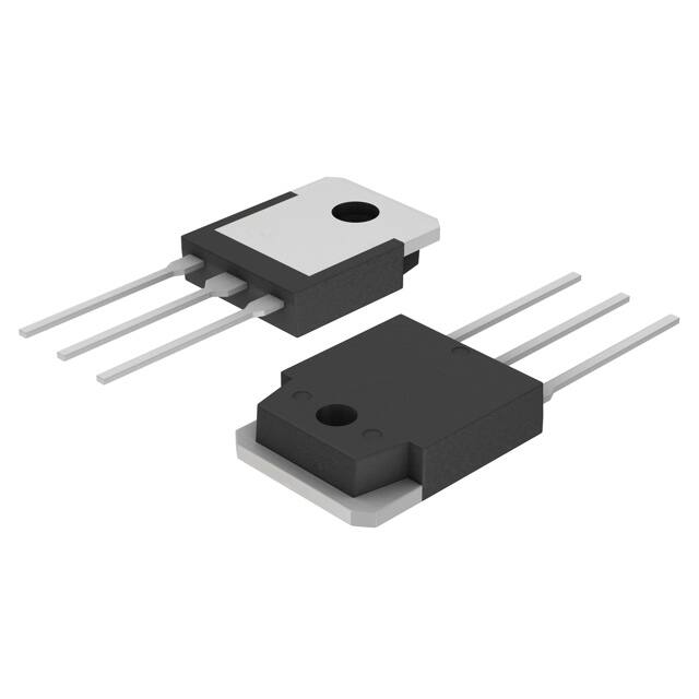
Figure 16. TO3PN, 3-Lead, Plastic, EIAJ SC-65
Package drawings are provided as a service to customers considering Fairchild components. Drawings may change in any manner
without notice. Please note the revision and/or date on the drawing and contact a Fairchild Semiconductor representative to verify or
obtain the most recent revision. Package specifications do not expand the terms of Fairchild’s worldwide terms and conditions, specifically the warranty therein, which covers Fairchild products.
Always visit Fairchild Semiconductor’s online packaging area for the most recent package drawings:
http://www.fairchildsemi.com/package/packageDetails.html?id=PN_TT3PN-003
©2010 Fairchild Semiconductor Corporation
FCA47N60 / FCA47N60_F109 Rev. 1
7
www.fairchildsemi.com
�tm
*Trademarks of System General Corporation, used under license by Fairchild Semiconductor.
DISCLAIMER
FAIRCHILD SEMICONDUCTOR RESERVES THE RIGHT TO MAKE CHANGES WITHOUT FURTHER NOTICE TO ANY PRODUCTS HEREIN TO IMPROVE
RELIABILITY, FUNCTION, OR DESIGN. FAIRCHILD DOES NOT ASSUME ANY LIABILITY ARISING OUT OF THE APPLICATION OR USE OF ANY
PRODUCT OR CIRCUIT DESCRIBED HEREIN; NEITHER DOES IT CONVEY ANY LICENSE UNDER ITS PATENT RIGHTS, NOR THE RIGHTS OF OTHERS.
THESE SPECIFICATIONS DO NOT EXPAND THE TERMS OF FAIRCHILD’S WORLDWIDE TERMS AND CONDITIONS, SPECIFICALLY THE WARRANTY
THEREIN, WHICH COVERS THESE PRODUCTS.
LIFE SUPPORT POLICY
FAIRCHILD’S PRODUCTS ARE NOT AUTHORIZED FOR USE AS CRITICAL COMPONENTS IN LIFE SUPPORT DEVICES OR SYSTEMS WITHOUT THE
EXPRESS WRITTEN APPROVAL OF FAIRCHILD SEMICONDUCTOR CORPORATION.
As used here in:
1. Life support devices or systems are devices or systems which, (a) are
intended for surgical implant into the body or (b) support or sustain life,
and (c) whose failure to perform when properly used in accordance with
instructions for use provided in the labeling, can be reasonably
expected to result in a significant injury of the user.
2.
A critical component in any component of a life support, device, or
system whose failure to perform can be reasonably expected to cause
the failure of the life support device or system, or to affect its safety or
effectiveness.
ANTI-COUNTERFEITING POLICY
Fairchild Semiconductor Corporation’s Anti-Counterfeiting Policy. Fairchild’s Anti-Counterfeiting Policy is also stated on our external website,
www.Fairchildsemi.com, under Sales Support.
Counterfeiting of semiconductor parts is a growing problem in the industry. All manufactures of semiconductor products are experiencing counterfeiting of their
parts. Customers who inadvertently purchase counterfeit parts experience many problems such as loss of brand reputation, substandard performance, failed
application, and increased cost of production and manufacturing delays. Fairchild is taking strong measures to protect ourselves and our customers from the
proliferation of counterfeit parts. Fairchild strongly encourages customers to purchase Fairchild parts either directly from Fairchild or from Authorized Fairchild
Distributors who are listed by country on our web page cited above. Products customers buy either from Fairchild directly or from Authorized Fairchild
Distributors are genuine parts, have full traceability, meet Fairchild’s quality standards for handing and storage and provide access to Fairchild’s full range of
up-to-date technical and product information. Fairchild and our Authorized Distributors will stand behind all warranties and will appropriately address and
warranty issues that may arise. Fairchild will not provide any warranty coverage or other assistance for parts bought from Unauthorized Sources. Fairchild is
committed to combat this global problem and encourage our customers to do their part in stopping this practice by buying direct or from authorized distributors.
PRODUCT STATUS DEFINITIONS
Definition of Terms
Datasheet Identification
Product Status
Definition
Advance Information
Formative / In Design
Datasheet contains the design specifications for product development. Specifications
may change in any manner without notice.
Preliminary
First Production
Datasheet contains preliminary data; supplementary data will be published at a later
date. Fairchild Semiconductor reserves the right to make changes at any time without
notice to improve design.
No Identification Needed
Full Production
Datasheet contains final specifications. Fairchild Semiconductor reserves the right to
make changes at any time without notice to improve the design.
Obsolete
Not In Production
Datasheet contains specifications on a product that is discontinued by Fairchild
Semiconductor. The datasheet is for reference information only.
Rev. I68
©2010 Fairchild Semiconductor Corporation
FCA47N60 / FCA47N60_F109 Rev. 1
8
www.fairchildsemi.com
FCA47N60 / FCA47N60_F109 — N-Channel SuperFET® MOSFET
TRADEMARKS
The following includes registered and unregistered trademarks and service marks, owned by Fairchild Semiconductor and/or its global subsidiaries, and is not
intended to be an exhaustive list of all such trademarks.
AccuPower™
F-PFS™
®*
®
AX-CAP®*
FRFET®
®
SM
Global Power Resource
PowerTrench
BitSiC™
TinyBoost®
GreenBridge™
PowerXS™
Build it Now™
TinyBuck®
Green FPS™
Programmable Active Droop™
CorePLUS™
TinyCalc™
®
Green FPS™ e-Series™
QFET
CorePOWER™
TinyLogic®
QS™
Gmax™
CROSSVOLT™
TINYOPTO™
Quiet Series™
GTO™
CTL™
TinyPower™
RapidConfigure™
IntelliMAX™
Current Transfer Logic™
TinyPWM™
ISOPLANAR™
DEUXPEED®
™
TinyWire™
Dual Cool™
Marking Small Speakers Sound Louder
TranSiC™
EcoSPARK®
Saving our world, 1mW/W/kW at a time™
and Better™
TriFault Detect™
EfficentMax™
SignalWise™
MegaBuck™
TRUECURRENT®*
ESBC™
SmartMax™
MICROCOUPLER™
μSerDes™
SMART START™
MicroFET™
®
Solutions for Your Success™
MicroPak™
®
SPM®
MicroPak2™
Fairchild
®
UHC®
STEALTH™
MillerDrive™
Fairchild Semiconductor
SuperFET®
Ultra FRFET™
MotionMax™
FACT Quiet Series™
SuperSOT™-3
UniFET™
mWSaver®
FACT®
®
OptoHiT™
SuperSOT™-6
VCX™
FAST
®
OPTOLOGIC
SuperSOT™-8
VisualMax™
FastvCore™
®
®
OPTOPLANAR
SupreMOS
VoltagePlus™
FETBench™
SyncFET™
XS™
FPS™
Sync-Lock™
仙童 ™
�