Is Now Part of
To learn more about ON Semiconductor, please visit our website at
www.onsemi.com
Please note: As part of the Fairchild Semiconductor integration, some of the Fairchild orderable part numbers
will need to change in order to meet ON Semiconductor’s system requirements. Since the ON Semiconductor
product management systems do not have the ability to manage part nomenclature that utilizes an underscore
(_), the underscore (_) in the Fairchild part numbers will be changed to a dash (-). This document may contain
device numbers with an underscore (_). Please check the ON Semiconductor website to verify the updated
device numbers. The most current and up-to-date ordering information can be found at www.onsemi.com. Please
email any questions regarding the system integration to Fairchild_questions@onsemi.com.
ON Semiconductor and the ON Semiconductor logo are trademarks of Semiconductor Components Industries, LLC dba ON Semiconductor or its subsidiaries in the United States and/or other countries. ON Semiconductor owns the rights to a number
of patents, trademarks, copyrights, trade secrets, and other intellectual property. A listing of ON Semiconductor’s product/patent coverage may be accessed at www.onsemi.com/site/pdf/Patent-Marking.pdf. ON Semiconductor reserves the right
to make changes without further notice to any products herein. ON Semiconductor makes no warranty, representation or guarantee regarding the suitability of its products for any particular purpose, nor does ON Semiconductor assume any liability
arising out of the application or use of any product or circuit, and specifically disclaims any and all liability, including without limitation special, consequential or incidental damages. Buyer is responsible for its products and applications using ON
Semiconductor products, including compliance with all laws, regulations and safety requirements or standards, regardless of any support or applications information provided by ON Semiconductor. “Typical” parameters which may be provided in ON
Semiconductor data sheets and/or specifications can and do vary in different applications and actual performance may vary over time. All operating parameters, including “Typicals” must be validated for each customer application by customer’s
technical experts. ON Semiconductor does not convey any license under its patent rights nor the rights of others. ON Semiconductor products are not designed, intended, or authorized for use as a critical component in life support systems or any FDA
Class 3 medical devices or medical devices with a same or similar classification in a foreign jurisdiction or any devices intended for implantation in the human body. Should Buyer purchase or use ON Semiconductor products for any such unintended
or unauthorized application, Buyer shall indemnify and hold ON Semiconductor and its officers, employees, subsidiaries, affiliates, and distributors harmless against all claims, costs, damages, and expenses, and reasonable attorney fees arising out
of, directly or indirectly, any claim of personal injury or death associated with such unintended or unauthorized use, even if such claim alleges that ON Semiconductor was negligent regarding the design or manufacture of the part. ON Semiconductor
is an Equal Opportunity/Affirmative Action Employer. This literature is subject to all applicable copyright laws and is not for resale in any manner.
�FDMS8020
N-Channel PowerTrench® MOSFET
30 V, 131 A, 2.5 mΩ
Features
General Description
Max rDS(on) = 2.5 mΩ at VGS = 10 V, ID = 26 A
Max rDS(on) = 3.6 mΩ at VGS = 4.5 V, ID = 21.5 A
This N-Channel MOSFET has been designed specifically to
improve the overall efficiency and to minimize switch node
ringing of DC/DC converters using either synchronous or
conventional switching PWM controllers.It has been optimized
for low gate charge, low rDS(on), fast switching speed ang body
diode reverse recovery performance.
Advanced Package and Silicon combination for low rDS(on)
and high efficiency
Next generation enhanced
engineered for soft recovery
body
diode
technology,
Applications
MSL1 robust package design
VRM Vcore Switching For Desktop And Server
100% UIL tested
OringFET / Load Switching
RoHS Compliant
DC-DC Conversion
Motor Bridge Switch
Bottom
Top
Pin 1
S
D
D
D
S
S
G
D
5
4
G
D
6
3
S
D
7
2
S
D
8
1
S
D
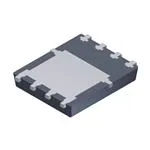
Power 56
MOSFET Maximum Ratings TA = 25 °C unless otherwise noted.
Symbol
VDS
Drain to Source Voltage
Parameter
VGS
Gate to Source Voltage
Drain Current -Continuous
ID
TC = 25 °C
-Continuous
TC = 100 °C
-Continuous
TA = 25 °C
-Pulsed
Single Pulse Avalanche Energy
EAS
PD
TJ, TSTG
TC = 25 °C
Power Dissipation
TA = 25 °C
Units
V
V
(Note 4)
±20
(Note 6)
131
(Note 6)
83
(Note 1a)
26
(Note 5)
507
(Note 3)
Power Dissipation
Ratings
30
93
65
(Note 1a)
Operating and Storage Junction Temperature Range
2.5
-55 to +150
A
mJ
W
°C
Thermal Characteristics
RθJC
Thermal Resistance, Junction-to-Case
RθJA
Thermal Resistance, Junction-to-Ambient
1.9
(Note 1a)
50
°C/W
Package Marking and Ordering Information
Device Marking
FDMS8020
Device
FDMS8020
©2011 Fairchild Semiconductor Corporation
FDMS8020 Rev. 1.3
Package
Power 56
1
Reel Size
13 ’’
Tape Width
12 mm
Quantity
3000 units
www.fairchildsemi.com
FDMS8020 N-Channel PowerTrench® MOSFET
May 2015
�Symbol
Parameter
Test Conditions
Min
Typ
Max
Units
Off Characteristics
BVDSS
Drain to Source Breakdown Voltage
ID = 250 μA, VGS = 0 V
ΔBVDSS
ΔTJ
Breakdown Voltage Temperature
Coefficient
ID = 250 μA, referenced to 25 °C
IDSS
Zero Gate Voltage Drain Current
VDS = 24 V, VGS = 0 V
IGSS
Gate to Source Leakage Current, Forward VGS = 20 V, VDS = 0 V
30
V
14
mV/°C
1
μA
100
nA
3.0
V
On Characteristics
VGS(th)
Gate to Source Threshold Voltage
VGS = VDS, ID = 250 μA
ΔVGS(th)
ΔTJ
Gate to Source Threshold Voltage
Temperature Coefficient
ID = 250 μA, referenced to 25 °C
-6
VGS = 10 V, ID = 26 A
2.0
rDS(on)
Static Drain to Source On Resistance
VGS = 4.5 V, ID = 21.5 A
2.6
3.6
VGS = 10 V, ID = 26 A, TJ = 125 °C
2.9
3.7
VDS = 5 V, ID = 26 A
154
gFS
Forward Transconductance
1.0
1.5
mV/°C
2.5
mΩ
S
Dynamic Characteristics
Ciss
Input Capacitance
Coss
Output Capacitance
Crss
Reverse Transfer Capacitance
Rg
Gate Resistance
VDS = 15 V, VGS = 0 V,
f = 1 MHz
2855
3800
pF
1050
1400
pF
115
175
pF
Ω
0.9
Switching Characteristics
12
22
VDD = 15 V, ID = 26 A,
VGS = 10 V, RGEN = 6 Ω
5.7
12
ns
32
52
ns
4
10
ns
Total Gate Charge
VGS = 0 V to 10 V
43
61
nC
VGS = 0 V to 4.5 V VDD = 15 V,
ID = 26 A
21
29
7.3
nC
6.0
nC
td(on)
Turn-On Delay Time
tr
Rise Time
td(off)
Turn-Off Delay Time
tf
Fall Time
Qg
Qg
Total Gate Charge
Qgs
Gate to Source Charge
Qgd
Gate to Drain “Miller” Charge
ns
nC
Drain-Source Diode Characteristics
VSD
Source to Drain Diode Forward Voltage
trr
Reverse Recovery Time
Qrr
Reverse Recovery Charge
trr
Reverse Recovery Time
Qrr
Reverse Recovery Charge
VGS = 0 V, IS = 2.1 A
(Note 2)
0.68
1.1
VGS = 0 V, IS = 26 A
(Note 2)
0.78
1.2
IF = 26 A, di/dt = 100 A/μs
IF = 26 A, di/dt = 300 A/μs
V
37
58
ns
18
33
nC
30
48
ns
36
57
nC
Notes:
1. RθJA is determined with the device mounted on a 1 in2 pad 2 oz copper pad on a 1.5 x 1.5 in. board of FR-4 material. RθCA is determined by the user's board design.
a) 50 °C/W when mounted on a
1 in2 pad of 2 oz copper
b) 125 °C/W when mounted on a
minimum pad of 2 oz copper.
2. Pulse Test: Pulse Width < 300 μs, Duty cycle < 2.0%.
3. Starting TJ = 25 °C; N-ch: L = 0.3 mH, IAS = 25 A, VDD = 27 V, VGS = 10 V.
4. As an N-ch device, the negative Vgs rating is for low duty cycle pulse occurrence only. No continuous rating is implied.
5. Pulsed Id please refer to SOA curve for more details.
6. Computed continuous current limited to Max Junction Temperature only, actual continuous current will be limited by thermal & electro-mechanical application board design.
©2011 Fairchild Semiconductor Corporation
FDMS8020 Rev. 1.3
2
www.fairchildsemi.com
FDMS8020 N-Channel PowerTrench® MOSFET
Electrical Characteristics TJ = 25 °C unless otherwise noted.
�5
VGS = 10 V
NORMALIZED
DRAIN TO SOURCE ON-RESISTANCE
ID, DRAIN CURRENT (A)
150
VGS = 4.5 V
120
VGS = 4 V
VGS = 3.5 V
90
VGS = 3 V
60
30
0
PULSE DURATION = 80 μs
DUTY CYCLE = 0.5% MAX
0
1
2
3
4
VGS = 3 V
4
VGS = 3.5 V
3
2
VGS = 4 V
1
0
5
0
30
Figure 1. On-Region Characteristics
90
120
150
Figure 2. Normalized On-Resistance
vs. Drain Current and Gate Voltage
1.6
10
ID = 26 A
VGS = 10 V
1.5
rDS(on), DRAIN TO
1.4
1.3
1.2
1.1
1.0
0.9
0.8
0.7
-75
-50
SOURCE ON-RESISTANCE (mΩ)
NORMALIZED
DRAIN TO SOURCE ON-RESISTANCE
60
ID, DRAIN CURRENT (A)
VDS, DRAIN TO SOURCE VOLTAGE (V)
150
IS, REVERSE DRAIN CURRENT (A)
VDS = 5 V
90
TJ = 150 oC
60
TJ = 25 oC
30
TJ = -55 oC
2.0
2.5
3.0
3.5
6
TJ = 125 oC
4
2
TJ = 25 oC
200
100
4
6
8
10
VGS = 0 V
10
1
TJ = 150 oC
TJ = 25 oC
0.1
TJ = -55 oC
0.01
0.001
0.0
4.0
VGS, GATE TO SOURCE VOLTAGE (V)
0.2
0.4
0.6
0.8
1.0
1.2
VSD, BODY DIODE FORWARD VOLTAGE (V)
Figure 5. Transfer Characteristics
©2011 Fairchild Semiconductor Corporation
FDMS8020 Rev. 1.3
8
Figure 4. On-Resistance vs. Gate to
Source Voltage
120
1.5
PULSE DURATION = 80 μs
DUTY CYCLE = 0.5% MAX
VGS, GATE TO SOURCE VOLTAGE (V)
PULSE DURATION = 80 μs
DUTY CYCLE = 0.5% MAX
0
1.0
ID = 26 A
0
2
-25
0
25 50 75 100 125 150
TJ, JUNCTION TEMPERATURE (oC)
Figure 3. Normalized On- Resistance
vs. Junction Temperature
ID, DRAIN CURRENT (A)
VGS = 4.5 V VGS = 10 V
PULSE DURATION = 80 μs
DUTY CYCLE = 0.5% MAX
Figure 6. Source to Drain Diode
Forward Voltage vs. Source Current
3
www.fairchildsemi.com
FDMS8020 N-Channel PowerTrench® MOSFET
Typical Characteristics TJ = 25 °C unless otherwise noted.
�10000
ID = 26 A
Ciss
8
VDD = 12 V
CAPACITANCE (pF)
VGS, GATE TO SOURCE VOLTAGE (V)
10
VDD = 18 V
6
VDD =15 V
4
Coss
1000
Crss
100
2
0
f = 1 MHz
VGS = 0 V
0
5
10
15
20
25
30
35
40
10
0.1
45
1
10
30
VDS, DRAIN TO SOURCE VOLTAGE (V)
Qg, GATE CHARGE (nC)
Figure 7. Gate Charge Characteristics
Figure 8. Capacitance vs. Drain
to Source Voltage
150
100
o
ID, DRAIN CURRENT (A)
IAS, AVALANCHE CURRENT (A)
RθJC = 1.9 C/W
TJ = 25 oC
10
TJ = 100 oC
120
VGS = 10 V
90
VGS = 4.5 V
60
30
TJ = 125 oC
1
0.01
0.1
1
10
0
25
100 300
P(PK), PEAK TRANSIENT POWER (W)
ID, DRAIN CURRENT (A)
125
150
10000
10 μs
100
100 μs
THIS AREA IS
LIMITED BY rDS(on)
1 ms
SINGLE PULSE
TJ = MAX RATED
RθJC = 1.9 oC/W
TC = 25 oC
0.1
0.1
100
Figure 10. Maximum Continuous Drain
Current vs. Case Temperature
1000
1
75
o
Figure 9. Unclamped Inductive
Switching Capability
10
50
TC, CASE TEMPERATURE ( C)
tAV, TIME IN AVALANCHE (ms)
10 ms
CURVE BENT TO
MEASURED DATA
1
10
DC
100
VDS, DRAIN to SOURCE VOLTAGE (V)
TC = 25 oC
1000
100
10 -5
10
-4
10
-3
10
-2
10
-1
10
1
t, PULSE WIDTH (sec)
Figure 11. Forward Bias Safe
Operating Area
©2011 Fairchild Semiconductor Corporation
FDMS8020 Rev. 1.3
SINGLE PULSE
RθJC = 1.9 oC/W
Figure 12. Single Pulse Maximum
Power Dissipation
4
www.fairchildsemi.com
FDMS8020 N-Channel PowerTrench® MOSFET
Typical Characteristics TJ = 25 °C unless otherwise noted.
�r(t), NORMALIZED EFFECTIVE TRANSIENT
THERMAL RESISTANCE
2
1
0.1
DUTY CYCLE-DESCENDING ORDER
D = 0.5
0.2
0.1
0.05
0.02
0.01
PDM
t1
t2
0.01
NOTES:
ZθJC(t) = r(t) x RθJC
RθJC = 1.9 oC/W
Peak TJ = PDM x ZθJC(t) + TC
Duty Cycle, D = t1 / t2
SINGLE PULSE
0.001 -5
10
-4
10
-3
-2
10
10
-1
10
1
t, RECTANGULAR PULSE DURATION (sec)
Figure 13. Junction-to-Case Transient Thermal Response Curve
©2011 Fairchild Semiconductor Corporation
FDMS8020 Rev. 1.3
5
www.fairchildsemi.com
FDMS8020 N-Channel PowerTrench® MOSFET
Typical Characteristics TJ = 25 °C unless otherwise noted.
�PQFN8 5X6, 1.27P
CASE 483AE
ISSUE A
5.10
PKG
CL
8
5.10
3.91
A
SEE
DETAIL B
B
5
1.27
8
7
6
5
0.77
4.52
PKG CL
5.85
5.65
6.15
3.75
6.61
KEEP OUT
AREA
1.27
1
4
1
TOP VIEW
2
3
4
0.61
1.27
3.81
OPTIONAL DRAFT
ANGLE MAY APPEAR
ON FOUR SIDES
OF THE PACKAGE
SEE
DETAIL C
5.00
4.80
LAND PATTERN
RECOMMENDATION
0.35
0.15
0.10 C
0.05
0.00
SIDE VIEW
8X
0.08 C
5.20
4.80
1.10
0.90
3.81
0.35
0.15
DETAIL C
SCALE: 2:1
1.27
0.51 (8X)
0.31
(0.34)
0.10
1
2
3
C A B
4
0.76
0.51
(0.52)
6.25
5.90
3.48+0.30
-0.10
(0.50)
(0.30)
(2X)
8
0.20+0.10
-0.15 (8X)
7
6
3.96
3.61
BOTTOM VIEW
0.30
0.05
5
C
SEATING
PLANE
DETAIL B
SCALE: 2:1
NOTES: UNLESS OTHERWISE SPECIFIED
A. PACKAGE STANDARD REFERENCE: JEDEC MO-240,
ISSUE A, VAR. AA,.
B. DIMENSIONS DO NOT INCLUDE BURRS OR MOLD FLASH.
MOLD FLASH OR BURRS DOES NOT EXCEED 0.10MM.
C. ALL DIMENSIONS ARE IN MILLIMETERS.
D. DIMENSIONING AND TOLERANCING PER ASME Y14.5M-2009.
E. IT IS RECOMMENDED TO HAVE NO TRACES OR
VIAS WITHIN THE KEEP OUT AREA.
�ON Semiconductor and
are trademarks of Semiconductor Components Industries, LLC dba ON Semiconductor or its subsidiaries in the United States and/or other countries.
ON Semiconductor owns the rights to a number of patents, trademarks, copyrights, trade secrets, and other intellectual property. A listing of ON Semiconductor’s product/patent
coverage may be accessed at www.onsemi.com/site/pdf/Patent−Marking.pdf. ON Semiconductor reserves the right to make changes without further notice to any products herein.
ON Semiconductor makes no warranty, representation or guarantee regarding the suitability of its products for any particular purpose, nor does ON Semiconductor assume any liability
arising out of the application or use of any product or circuit, and specifically disclaims any and all liability, including without limitation special, consequential or incidental damages.
Buyer is responsible for its products and applications using ON Semiconductor products, including compliance with all laws, regulations and safety requirements or standards,
regardless of any support or applications information provided by ON Semiconductor. “Typical” parameters which may be provided in ON Semiconductor data sheets and/or
specifications can and do vary in different applications and actual performance may vary over time. All operating parameters, including “Typicals” must be validated for each customer
application by customer’s technical experts. ON Semiconductor does not convey any license under its patent rights nor the rights of others. ON Semiconductor products are not
designed, intended, or authorized for use as a critical component in life support systems or any FDA Class 3 medical devices or medical devices with a same or similar classification
in a foreign jurisdiction or any devices intended for implantation in the human body. Should Buyer purchase or use ON Semiconductor products for any such unintended or unauthorized
application, Buyer shall indemnify and hold ON Semiconductor and its officers, employees, subsidiaries, affiliates, and distributors harmless against all claims, costs, damages, and
expenses, and reasonable attorney fees arising out of, directly or indirectly, any claim of personal injury or death associated with such unintended or unauthorized use, even if such
claim alleges that ON Semiconductor was negligent regarding the design or manufacture of the part. ON Semiconductor is an Equal Opportunity/Affirmative Action Employer. This
literature is subject to all applicable copyright laws and is not for resale in any manner.
PUBLICATION ORDERING INFORMATION
LITERATURE FULFILLMENT:
Literature Distribution Center for ON Semiconductor
19521 E. 32nd Pkwy, Aurora, Colorado 80011 USA
Phone: 303−675−2175 or 800−344−3860 Toll Free USA/Canada
Fax: 303−675−2176 or 800−344−3867 Toll Free USA/Canada
Email: orderlit@onsemi.com
© Semiconductor Components Industries, LLC
N. American Technical Support: 800−282−9855 Toll Free
USA/Canada
Europe, Middle East and Africa Technical Support:
Phone: 421 33 790 2910
Japan Customer Focus Center
Phone: 81−3−5817−1050
www.onsemi.com
1
ON Semiconductor Website: www.onsemi.com
Order Literature: http://www.onsemi.com/orderlit
For additional information, please contact your local
Sales Representative
www.onsemi.com
�