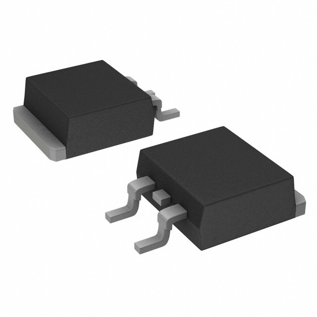
EcoSPARK®2 320mJ, 450V, N-Channel Ignition IGBT
Features
General Description
SCIS Energy = 320mJ at TJ = 25oC
The FGB3245G2-F085 and FGD3245G2 are N-channel
IGBTs designed in ON Semiconductor's EcoSPARK-2
technology which helps in eliminating external protection
circuitry. The technology is optimized for driving the coil
in the harsh environment of automotive ignition systems
and offers out-standing Vsat and SCIS Energy capability
also at elevated operating temperatures. The logic level
gate input is ESD protected and features an integrated
gate resistor. An inte-grated zener-circuitry clamps the
IGBT's collecter- to-emit-ter voltage at 450V which
enables systems requiring a higher spark voltage
Logic Level Gate Drive
Low Saturation Voltage
Qualified to AEC Q101
RoHS Compliant
Applications
Automotive lgnition Coil Driver Circuits
Coil On Plug Applications
Package
Symbol
JEDEC TO-263AB
D²-Pak
COLLECTOR
G
COLLECTOR
(FLANGE)
E
R1
GATE
R2
JEDEC TO-252AA
D-Pak
G
EMITTER
COLLECTOR
(FLANGE)
E
@2014 Semiconductor Components Industries, LLC.
August-2017, Rev. 3
Publication Order Number:
FGD3245G2-F085/D
FGD3245G2-F085 / FGB3245G2-F085
FGD3245G2-F085 / FGB3245G2-F085
�Symbol
Parameter
BVCER Collector to Emitter Breakdown Voltage (IC = 1mA)
Rating
450
Units
V
BVECS
Emitter to Collector Voltage - Reverse Battery Condition (IC = 10mA)
28
V
ESCIS25
Self Clamping Inductive Switching Energy (Note 1)
320
mJ
ESCIS150 Self Clamping Inductive Switching Energy (Note 2)
180
mJ
IC25
Collector Current Continuous, at VGE = 4.0V, TC = 25°C
23
A
IC110
Collector Current Continuous, at VGE = 4.0V, TC = 110°C
23
A
VGEM
Gate to Emitter Voltage Continuous
±10
V
Power Dissipation Total, at TC = 25°C
150
W
1.1
W/oC
PD
Power Dissipation Derating, for TC > 25oC
TJ
Operating Junction Temperature Range
-40 to +175
o
C
TSTG
Storage Junction Temperature Range
-40 to +175
o
C
TL
Max. Lead Temp. for Soldering (Leads at 1.6mm from case for 10s)
300
o
C
TPKG
Max. Lead Temp. for Soldering (Package Body for 10s)
260
o
C
ESD
Electrostatic Discharge Voltage at100pF, 1500Ω
4
kV
CDM-Electrostatic Discharge Voltage at 1Ω
2
kV
Package Marking and Ordering Information
Device Marking
FGD3245G2
Device
FGD3245G2-F085
Package
TO252AA
Reel Size
330mm
Tape Width
16mm
Quantity
2500 units
FGB3245G2
FGB3245G2-F085
TO263AB
330mm
24mm
800 units
Electrical Characteristics TA = 25°C unless otherwise noted
Symbol
Parameter
Test Conditions
Min
Typ
Max Units
Off State Characteristics
BVCER
ICE = 2mA, VGE = 0,
Collector to Emitter Breakdown Voltage RGE = 1KΩ,
TJ = -40 to 150oC
420
-
480
V
BVCES
ICE = 10mA, VGE = 0V,
Collector to Emitter Breakdown Voltage RGE = 0,
TJ = -40 to 150oC
440
-
500
V
BVECS
Emitter to Collector Breakdown Voltage
ICE = -75mA, VGE = 0V,
TJ = 25°C
28
-
-
V
BVGES
Gate to Emitter Breakdown Voltage
IGES = ±2mA
±12
±14
-
V
Collector to Emitter Leakage Current
VCE = 250V, RGE = 1KΩ
-
-
25
μA
-
-
1
mA
IECS
Emitter to Collector Leakage Current
VEC = 24V,
-
-
1
-
-
40
R1
Series Gate Resistance
-
120
-
Ω
R2
Gate to Emitter Resistance
10K
-
30K
Ω
ICER
TJ = 25oC
TJ = 150oC
TJ = 25oC
TJ = 150oC
mA
On State Characteristics
VCE(SAT) Collector to Emitter Saturation Voltage ICE = 6A, VGE = 4V,
VCE(SAT) Collector to Emitter Saturation Voltage ICE = 10A, VGE = 4.5V,
VCE(SAT) Collector to Emitter Saturation Voltage ICE = 15A, VGE = 4.5V,
www.onsemi.com
2
TJ = 25oC
TJ = 150oC
TJ = 150oC
-
1.13
1.25
V
-
1.32
1.50
V
-
1.64
1.85
V
FGD3245G2-F085 / FGB3245G2-F085
Device Maximum Ratings TA = 25°C unless otherwise noted
�Symbol
Parameter
Test Conditions
Min
Typ
-
23
Max Units
Dynamic Characteristics
QG(ON)
Gate Charge
ICE = 10A, VCE = 12V,
VGE = 5V
-
nC
1.3
1.6
2.2
0.75
1.1
1.8
VCE = 12V, ICE = 10A
-
2.7
-
V
Current Turn-On Delay Time-Resistive VCE = 14V, RL = 1Ω
VGE = 5V, RG = 1KΩ
Current Rise Time-Resistive
TJ = 25oC,
-
0.9
4
μs
-
2.6
7
μs
-
5.4
15
μs
-
2.7
15
μs
-
-
320
mJ
-
-
0.9
VGE(TH)
Gate to Emitter Threshold Voltage
ICE = 1mA, VCE = VGE,
VGEP
Gate to Emitter Plateau Voltage
TJ =
25oC
TJ = 150oC
V
Switching Characteristics
td(ON)R
trR
td(OFF)L
tfL
ESCIS
Current Turn-Off Delay Time-Inductive VCE = 300V, L = 1mH,
VGE = 5V, RG = 1KΩ
Current Fall Time-Inductive
ICE = 6.5A, TJ = 25oC,
L = 3.0 mHy,RG = 1KΩ,
Self Clamped Inductive Switching
VGE = 5V, (Note 1)
TJ = 25°C
Thermal Characteristics
RθJC
Thermal Resistance Junction to Case
All packages
o
C/W
Notes:
1: Self Clamping Inductive Switching Energy (ESCIS25) of 320 mJ is based on the test conditions that starting
Tj=25oC; L=3mHy, ISCIS=14.6A,VCC=100V during inductor charging and VCC=0V during the time in clamp.
2: Self Clamping Inductive Switching Energy (ESCIS150) of 180 mJ is based on the test conditions that starting
Tj=150oC; L=3mHy, ISCIS=10.9A,VCC=100V during inductor charging and VCC=0V during the time in clamp.
www.onsemi.com
3
FGD3245G2-F085 / FGB3245G2-F085
Electrical Characteristics TA = 25°C unless otherwise noted
�o
TJ = 150 C
10
1
SCIS Curves valid for Vclamp Voltages of
