IGBT - Field Stop, Trench
650 V, 75 A
FGH75T65SHDTL4
Description
Using novel field stop IGBT technology, ON Semiconductor’s new
series of field stop 3rd generation IGBTs offer the optimum
performance for solar inverter, UPS, welder, telecom, ESS and PFC
applications where low conduction and switching losses are essential.
www.onsemi.com
Features
•
•
•
•
•
•
•
•
•
•
Maximum Junction Temperature: TJ =175°C
Positive Temperature Co−efficient for Easy Parallel Operating
High Current Capability
Low Saturation Voltage: VCE(sat) = 1.6 V (Typ.) @ IC = 75 A
100% of the Parts Tested for ILM
High Input Impedance
Fast Switching
Tighten Parameter Distribution
This Device is Pb−Free and is RoHS Compliant
Do Not Recommend for Reflow and Full PKG Dipping
VCES
IC
650 V
75 A
C
E1: Kelvin Emitter
E2: Power Emitter
G
E1
E2
Applications
• Solar Inverter, UPS, Welder, Telecom, ESS, PFC
C
E2
E1
G
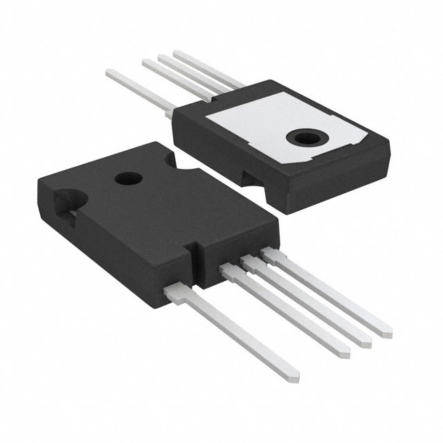
TO−247−4LD
CASE 340CJ
MARKING DIAGRAM
$Y&Z&3&K
FGH75T65
SHDTL4
$Y
= ON Semiconductor Logo
&Z
= Assembly Plant Code
&3
= Numeric Date Code
&K
= Lot Code
FGH75T65SHDTL4 = Specific Device Code
ORDERING INFORMATION
See detailed ordering and shipping information on page 2 of
this data sheet.
© Semiconductor Components Industries, LLC, 2015
December, 2019 − Rev. 2
1
Publication Order Number:
FGH75T65SHDTL4/D
�FGH75T65SHDTL4
ABSOLUTE MAXIMUM RATINGS
Symbol
FGH75T65SHDTL4
Unit
VCES
Collector to Emitter Voltage
650
V
VGES
Gate to Emitter Voltage
±20
V
Transient Gate to Emitter Voltage
±30
V
TC = 25°C
150
A
TC = 100°C
75
A
TC = 25°C
300
A
300
A
IC
Description
Collector Current
ILM (Note 1)
Pulsed Collector Current
ICM (Note 2)
Pulsed Collector Current
IF
IFM(Note 2)
Diode Forward Current
TC = 25°C
125
A
Diode Forward Current
TC = 100°C
75
A
300
A
455
W
Pulsed Diode Maximum Forward Current
PD
Maximum Power Dissipation
227
W
TJ
Operating Junction Temperature
−55 to +175
°C
Storage Temperature Range
−55 to +175
°C
300
°C
TC = 25°C
TC = 100°C
TSTG
TL
Maximum Lead Temp. for Soldering Purposes, 1/8” from Case for 5 Seconds
Stresses exceeding those listed in the Maximum Ratings table may damage the device. If any of these limits are exceeded, device functionality
should not be assumed, damage may occur and reliability may be affected.
1. VCC = 400 V, VGE = 15 V, IC = 300 A, RG = 73 �, Inductive Load.
2. Repetitive rating: Pulse width limited by max. junction temperature.
THERMAL CHARACTERISTICS
Symbol
Parameter
FGH75T65SHDTL4
Unit
R�JC (IGBT)
Thermal Resistance, Junction to Case, Max.
0.33
_C/W
R�JC (Diode)
Thermal Resistance, Junction to Case, Max.
0.65
_C/W
40
_C/W
Thermal Resistance, Junction to Ambient, Max.
R�JA
PACKAGE MARKING AND ORDERING INFORMATION
Part Number
Top Mark
Package
Packing
Method
Reel Size
Tape Width
Quantity
FGH75T65SHDTL4
FGH75T65SHDTL4
TO−247−4LD
Tube
−
−
30
ELECTRICAL CHARACTERISTICS OF THE IGBT (TC = 25°C unless otherwise noted)
Parameter
Symbol
Test Conditions
Min
Typ
Max
Unit
650
−
−
V
OFF CHARACTERISTICS
Collector to Emitter Breakdown Voltage
VGE = 0 V, IC = 1 mA
Temperature Coefficient of Breakdown Voltage
IC = 1 mA, Reference to 25°C
−
0.65
−
V/°C
ICES
Collector Cut−Off Current
VCE = VCES, VGE = 0 V
−
−
250
�A
IGES
G−E Leakage Current
VGE = VGES, VCE = 0 V
−
−
±400
nA
BVCES
� BVCES /
� TJ
ON CHARACTERISTICS
VGE(th)
G−E Threshold Voltage
IC = 75 mA, VCE = VGE
4.0
5.5
7.5
V
VCE(sat)
Collector to Emitter Saturation Voltage
IC = 75 A, VGE = 15 V
−
1.6
2.1
V
IC = 75 A, VGE = 15 V,
TC = 175°C
−
2.28
−
V
www.onsemi.com
2
�FGH75T65SHDTL4
ELECTRICAL CHARACTERISTICS OF THE IGBT (TC = 25°C unless otherwise noted) (continued)
Symbol
Parameter
Test Conditions
Min
Typ
Max
Unit
−
3710
−
pF
−
183
−
pF
−
43
−
pF
−
55
−
ns
−
50
−
ns
Turn−Off Delay Time
−
189
−
ns
Fall Time
−
39
−
ns
Eon
Turn−On Switching Loss
−
1.06
−
mJ
Eoff
Turn−Off Switching Loss
−
1.56
−
mJ
Ets
Total Switching Loss
−
2.62
−
mJ
Td(on)
Turn−On Delay Time
−
48
−
ns
−
56
−
ns
Turn−Off Delay Time
−
205
−
ns
Fall Time
−
40
−
ns
Eon
Turn−On Switching Loss
−
2.34
−
mJ
Eoff
Turn−Off Switching Loss
−
1.81
−
mJ
Ets
Total Switching Loss
−
4.15
−
mJ
Qg
Total Gate Charge
−
126
−
nC
Qge
Gate to Emitter Charge
−
24.1
−
nC
Qgc
Gate to Collector Charge
−
47.6
−
nC
DYNAMIC CHARACTERISTICS
Cies
Input Capacitance
Coes
Output Capacitance
Cres
Reverse Transfer Capacitance
VCE = 30 V, VGE = 0 V,
f = 1 MHz
SWITCHING CHARACTERISTICS
Td(on)
Tr
Td(off)
Tf
Tr
Td(off)
Tf
VCC = 400 V, IC = 75 A,
RG = 15 �, VGE = 15 V,
Inductive Load, TC = 25°C
Turn−On Delay Time
Rise Time
VCC = 400 V, IC = 75 A,
RG = 15 �, VGE = 15 V,
Inductive Load, TC = 25°C
Rise Time
VCE = 400 V, IC = 75 A,
VGE = 15 V
Product parametric performance is indicated in the Electrical Characteristics for the listed test conditions, unless otherwise noted. Product
performance may not be indicated by the Electrical Characteristics if operated under different conditions.
ELECTRICAL CHARACTERISTICS OF THE DIODE (TC = 25°C unless otherwise noted)
Symbol
VFM
Erec
Trr
Qrr
Parameter
Diode Forward Voltage
Reverse Recovery Energy
Diode Reverse Recovery Time
Test Conditions
IF = 75 A
IF = 75 A,
dIF/dt = 200 A/�s
Diode Reverse Recovery Charge
Min
Typ
Max
Unit
TC = 25°C
−
1.8
2.1
V
TC = 175°C
−
1.7
−
TC = 175°C
−
160
−
�J
TC = 25°C
−
76
−
ns
TC = 175°C
−
270
−
TC = 25°C
−
206
−
TC = 175°C
−
2199
−
nC
Product parametric performance is indicated in the Electrical Characteristics for the listed test conditions, unless otherwise noted. Product
performance may not be indicated by the Electrical Characteristics if operated under different conditions.
www.onsemi.com
3
�FGH75T65SHDTL4
TYPICAL PERFORMANCE CHARACTERISTICS
o
TC = 25 C
20V
12V
Collector Current, IC [A]
240
300
15V
10V
180
120
VGE = 8V
60
0
0
1
2
3
4
5
Collector−Emitter Voltage, VCE [V]
240
4
Collector−Emitter Voltage, VCE [V]
Collector Current, IC [A]
0
o
TC = 25 C
o
180
120
60
0
1
2
3
4
5
Collector−Emitter Voltage, VCE [V]
6
Collector−Emitter Voltage, VCE [V]
16
12
75A
150A
4
8
12
16
Gate−Emitter Voltage, VGE [V]
150A
75A
2
IC = 40A
Common Emitter
o
o
4
3
20
TC = 25 C
IC = 40A
Common Emitter
VGE = 15V
Figure 4. Saturation Voltage vs. Case
Temperature at Variant Current Level
Common Emitter
8
6
1
−100
−50
0
50
100
150
200
o
Collector−Emitter Case Temperature, TC [ C]
Figure 3. Typical Saturation
Voltage Characteristics
20
1
2
3
4
5
Collector−Emitter Voltage, VCE [V]
Figure 2. Typical Output Characteristics
TC = 175 C
Collector−Emitter Voltage, VCE [V]
VGE = 8V
60
0
Common Emitter
VGE = 15V
0
10V
120
300
0
15V
12V
180
6
Figure 1. Typical Output Characteristics
240
20V
o
TC = 175 C
Collector Current, IC [A]
300
TC = 175 C
16
12
Figure 5. Saturation Voltage vs. VGE
IC = 40A
4
0
20
75A
8
4
150A
8
12
16
Gate−Emitter Voltage, VGE [V]
Figure 6. Saturation Voltage vs. VGE
www.onsemi.com
4
20
�FGH75T65SHDTL4
TYPICAL PERFORMANCE CHARACTERISTICS (Continued)
15
10000
Common Emitter
Gate−Emitter Voltage, VGE [V]
o
Capacitance [pF]
Cies
1000
Coes
100
Cres
Common Emitter
VGE = 0V, f = 1MHz
TC = 25 C
12
300V
VCC = 200V
9
400V
6
3
o
TC = 25 C
10
1
10
Collector−Emitter Voltage, VCE [V]
0
30
0
25
50
Figure 7. Capacitance Characteristics
100
125
Figure 8. Gate Charge Characteristics
400
1000
Common Emitter
VCC = 400V, V GE = 15V
IC = 75A
td(off)
o
TC = 25 C
Switching Time [ns]
Switching Time [ns]
75
Gate Charge, Qg [nC]
o
TC = 175 C
tr
100
td(on)
100
Common Emitter
VCC = 400V, VGE = 15V
IC = 75A
tf
o
TC = 25 C
o
TC = 175 C
30
10
20
30
40
Gate Resistance, RG [W]
10
10
50
Figure 9. Turn−on Characteristics vs.
Gate Resistance
20
30
40
Gate Resistance, RG [W]
50
Figure 10. Turn−off Characteristics
vs. Gate Resistance
100
5
Eoff
Eon
1
Switching Time [ns]
Switching Loss [mJ]
td(on)
Common Emitter
VCC = 400V, VGE = 15V
IC = 75A
tr
Common Emitter
VGE = 15V, RG = 15 W
o
o
TC = 25 C
TC = 25 C
o
10
TC = 175 C
0.4
10
20
30
40
Gate Resistance, RG [W]
8
15
50
o
TC = 175 C
30
45
60
75
Collector Current, IC [A]
Figure 11. Switching Loss vs.
Gate Resistance
Figure 12. Turn−on Characteristics
vs. Collector Current
www.onsemi.com
5
150
�FGH75T65SHDTL4
TYPICAL PERFORMANCE CHARACTERISTICS (Continued)
400
5
Eoff
Switching Loss [mJ]
Switching Time [ns]
td(off)
100
tf
Common Emitter
VGE = 15V, RG = 15 W
1
Eon
Common Emitter
VGE = 15V, RG = 15 W
o
o
TC = 25 C
TC = 25 C
o
o
TC = 175 C
TC = 175 C
10
15
30
45
60
0.1
15
75
30
Collector Current, I C [A]
Figure 13. Turn−off Characteristics
vs. Collector Current
375
o
TC = 25 C
o
TC = 75 C
o
TC = 100 C
75
0
1k
10k
100k
Switching Frequency, f[Hz]
*Notes:
1.TC = 255C
2.TJ = 1755C
3.Single Pulse
1
0.1
1M
100ms
1ms
10 ms
DC
10
Figure 15. Load Current vs. Frequency
1
20
o
o
TJ = 25 C
10
o
TJ = 75 C
o
TC = 25 C
o
TC = 75 C
o
TC = 25 C
Reverse Recovery Currnet, Irr [A]
100
TJ = 175 C
10
100
1000
Collector−Emitter Voltage, VCE [V]
Figure 16. SOA Characteristics
300
Forward Current, IF [A]
10ms
100
VGE = 15/0V, RG = 15 W
Collector Current, I c [A]
Collector Current, [A]
o
150
75
300
TJ