Is Now Part of
To learn more about ON Semiconductor, please visit our website at
www.onsemi.com
Please note: As part of the Fairchild Semiconductor integration, some of the Fairchild orderable part numbers
will need to change in order to meet ON Semiconductor’s system requirements. Since the ON Semiconductor
product management systems do not have the ability to manage part nomenclature that utilizes an underscore
(_), the underscore (_) in the Fairchild part numbers will be changed to a dash (-). This document may contain
device numbers with an underscore (_). Please check the ON Semiconductor website to verify the updated
device numbers. The most current and up-to-date ordering information can be found at www.onsemi.com. Please
email any questions regarding the system integration to Fairchild_questions@onsemi.com.
ON Semiconductor and the ON Semiconductor logo are trademarks of Semiconductor Components Industries, LLC dba ON Semiconductor or its subsidiaries in the United States and/or other countries. ON Semiconductor owns the rights to a number
of patents, trademarks, copyrights, trade secrets, and other intellectual property. A listing of ON Semiconductor’s product/patent coverage may be accessed at www.onsemi.com/site/pdf/Patent-Marking.pdf. ON Semiconductor reserves the right
to make changes without further notice to any products herein. ON Semiconductor makes no warranty, representation or guarantee regarding the suitability of its products for any particular purpose, nor does ON Semiconductor assume any liability
arising out of the application or use of any product or circuit, and specifically disclaims any and all liability, including without limitation special, consequential or incidental damages. Buyer is responsible for its products and applications using ON
Semiconductor products, including compliance with all laws, regulations and safety requirements or standards, regardless of any support or applications information provided by ON Semiconductor. “Typical” parameters which may be provided in ON
Semiconductor data sheets and/or specifications can and do vary in different applications and actual performance may vary over time. All operating parameters, including “Typicals” must be validated for each customer application by customer’s
technical experts. ON Semiconductor does not convey any license under its patent rights nor the rights of others. ON Semiconductor products are not designed, intended, or authorized for use as a critical component in life support systems or any FDA
Class 3 medical devices or medical devices with a same or similar classification in a foreign jurisdiction or any devices intended for implantation in the human body. Should Buyer purchase or use ON Semiconductor products for any such unintended
or unauthorized application, Buyer shall indemnify and hold ON Semiconductor and its officers, employees, subsidiaries, affiliates, and distributors harmless against all claims, costs, damages, and expenses, and reasonable attorney fees arising out
of, directly or indirectly, any claim of personal injury or death associated with such unintended or unauthorized use, even if such claim alleges that ON Semiconductor was negligent regarding the design or manufacture of the part. ON Semiconductor
is an Equal Opportunity/Affirmative Action Employer. This literature is subject to all applicable copyright laws and is not for resale in any manner.
�FSAM50SM60A
Motion SPM® 2 系列
特性
概述
• 通过 UL 第 E209204 号认证 (UL1557)
• 600 V - 50 A 三相 IGBT 逆变器,包含栅极驱动和
保护的控制 IC
• 低损耗、短路额定的 IGBT
• 采用 DBC (Al2O3) 基板实现非常低的热阻
• 低端 IGBT 的独立发射极开路引脚用于三相电流感
测
• 单接地电源供电
• 针对 5 kHz 开关频率进行优化
FSAM50SM60A 是 Motion SPM® 2 模块,为交流感
应、无刷直流电机和 PMSM 电机提供非常全面的高
性能逆变平台。这些模块综合优化了内置 IGBT 的栅
极驱动以最小化电磁干扰和能量损耗。同时也提供多
重模组保护特性,集成欠压闭锁,过流保护,热量监
测和故障报告。内置的高速 HVIC 只需要一个单电源
电压,将逻辑电平栅极输入转化为适合驱动模块内部
IGBT 的高电压,高电流驱动信号。独立的 IGBT 负端
在每个相位均有效,可支持大量不同种类的控制算
法。
• 内置负温度系数热敏电阻可实现温度监测
• 逆变器的额定功率为 4.0 kW / 100~253 VAC
• 通过 sense-IGBT 发射极改变串联电阻值可调整电
流保护水平
• 绝缘等级:2500 Vrms / 分钟
应用
• 运动控制 - 家用设备 / 工业电机
资料
• AN-9043 - Motion SPM® 2 Series User's Guide
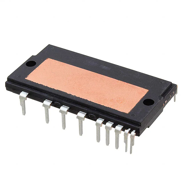
图 1. 封装概览
封装标识与定购信息
器件
FSAM50SM60A
©2006 飞兆半导体公司
FSAM50SM60A Rev. C4
器件标识
FSAM50SM60A
封装
包装类型
数量
S32CA-032
Rail
8
1
www.fairchildsemi.com
FSAM50SM60A Motion SPM® 2 系列
2014 年 7 月
�FSAM50SM60A Motion SPM® 2 系列
集成的功率功能
• 600V - 50 A IGBT 逆变器,适用于三相 DC / AC 功率转换 (请参阅图 3)
集成的驱动、保护和系统控制功能
• 对于逆变器高端 IGBT:栅极驱动电路、高压隔离的高速电平转换,控制电路欠压锁定保护 (UVLO)
注意:可用自举电路示例如图 13 和图 14 所示。
• 对于逆变器低端 IGBT:栅极驱动电路、短路保护 (SCP)、控制电源欠压锁定 (UVLO)保护
• 温度监测:系统温度监测使用内置的热敏电阻
注意:可用温度监测电路示例如图 14 所示。
• 故障信号:对应短路故障 (低端 IGBT )和 UV 故障 (低端控制电源 )
• 输入接口:低电平有效接口,可用于 3.3 / 5 V 逻辑电平,施密特触发脉冲输入
引脚布局
(1)VCC(L)
(2)COM(L)
(3)IN(UL)
(4)IN(VL)
(5)IN(WL)
(6)COM(L)
(24)VTH
(25)RTH
(26)NU
(27)NV
(7)VFO
(8)CFOD
(9)CSC
(28)NW
(10)RSC
(11)IN(UH)
(29)U
(12)VCC(UH)
(13)VB(U)
C ase Tem p erature(T C )
D etecting P o int
(30)V
(14)VS(U)
(15)INV(H)
(16)COM(H)
(17)VCC(VH)
(31)W
(18)VB(V)
D B C S ub strate
(19)VS(V)
(20)IN(WH)
(32)P
(21)VCC(WH)
(22)VB(W)
(23)VS(W)
图 2. 俯视图
©2006 飞兆半导体公司
FSAM50SM60A Rev. C4
2
www.fairchildsemi.com
�FSAM50SM60A Motion SPM® 2 系列
引脚描述
引脚号
1
引脚名
VCC(L)
IC 和 IGBT 驱动的低端公共偏压
2
COM(L)
低端公共电源接地
3
IN(UL)
低端 U 相的信号输入端
4
IN(VL)
低端 V 相的信号输入端
5
IN(WL)
低端 W 相的信号输入端
6
COM(L)
低端公共电源接地
7
VFO
8
CFOD
设置故障输出持续时间的电容
9
CSC
短路电流感测输入电容 (低通滤波器)
10
RSC
短路电流感测电阻
11
IN(UH)
12
VCC(UH)
13
VB(U)
U 相 IGBT 驱动的高端偏压
14
VS(U)
U 相 IGBT 驱动的高端偏压接地
15
IN(VH)
高端 V 相的信号输入
16
COM(H)
高端公共电源接地
17
VCC(VH)
V 相 IC 的高端偏压
18
VB(V)
V 相 IGBT 驱动的高端偏压
19
VS(V)
V 相 IGBT 驱动的高端偏压接地
20
IN(WH)
21
VCC(WH)
22
VB(W)
W 相 IGBT 驱动的高端偏压
23
VS(W)
W 相 IGBT 驱动的高端偏压接地
24
VTH
热敏电阻偏压
25
RTH
用于热敏电阻 (温度检测)的串连电阻
26
NU
U 相的直流输入端负端
27
NV
V 相的直流输入端负端
28
NW
W 相的直流输入端负端
29
U
U 相输出
30
V
V 相输出
31
W
W 相输出
32
P
直流输入正端
©2006 飞兆半导体公司
FSAM50SM60A Rev. C4
引脚描述
故障输出
高端 U 相的信号输入
U 相 IC 的高端偏压
高端 W 相的信号输入
W 相 IC 的高端偏压
3
www.fairchildsemi.com
�FSAM50SM60A Motion SPM® 2 系列
内部等效电路与输入 / 输出引脚
(22) VB(W)
(21) VCC(WH)
(20) IN(WH)
(23) VS(W)
(18) VB(V)
(17) VCC(VH)
(16) COM(H)
(15) IN(VH)
(19) VS(V)
(13) VB(U)
(12) VCC(UH)
(11) IN(UH)
(14) VS(U)
P (32)
VB
VCC
OUT
COM
IN
W (31)
VS
VB
VCC
OUT
COM
IN
VS
V (30)
VB
VCC
OUT
COM
IN
U (29)
VS
(10) RSC
(9) CSC
(8) CFOD
(7) VFO
(6) COM(L)
(5) IN(WL)
(4) IN(VL)
(3) IN(UL)
(2) COM(L)
(1) VCC(L)
C(SC) OUT(WL)
C(FOD)
NW (28)
VFO
IN(WL) OUT(VL)
IN(VL)
NV (27)
IN(UL)
COM(L)
OUT(UL)
VCC
NU (26)
RTH (25)
THERMISTOR
VTH (24)
图 3. 内部框图
注:
1. 逆变器的低端由三个 sense-IGBT 组成,每个 IGBT 分别带有续流二极管,以及一个带有栅极驱动、电流感测和保护功能的控制 IC。
2. 逆变器的功率端由逆变器的四个直流输入引脚和三个输出引脚组成。
3. 逆变器高端由三个常规 IGBT 以及相应的续流二极管和驱动 IC 组成。
©2006 飞兆半导体公司
FSAM50SM60A Rev. C4
4
www.fairchildsemi.com
�逆变器部分
项目
符号
VDC
电源电压
条件
施加于直流线路
VPN (浪涌) 施加在 P 和 N 之间
VCES
电源电压 (浪涌)
集电极 - 发射极之间电压
额定值
450
单位
V
500
V
600
V
单个 IGBT 的集电极电流
± IC
TC = 25°C
50
A
单个 IGBT 的集电极电流
± IC
TC = 100°C
25
A
单个 IGBT 的集电极电流 (峰值)
± ICP
TC = 25°C,脉冲宽度小于 1 ms
100
A
集电极功耗
PC
TC = 25°C,单个芯片
100
W
工作结温
TJ
(注 1)
-20 ~ 125
°C
注:
1. 为保证安全工作,建议平均结温应限制为 TJ 125C (at TC 100C)。
控制部分
符号
条件
额定值
单位
控制电源电压
项目
VCC
施加在 VCC(UH), VCC(VH), VCC(WH) - COM(H), VCC(L) COM(L)
20
V
高端控制偏压
VBS
施加在 VB(U) - VS(U), VB(V) - VS(V), VB(W) - VS(W)
20
V
输入信号电压
VIN
施加在 IN(UH), IN(VH), IN(WH) - COM(H)
IN(UL), IN(VL), IN(WL) - COM(L)
-0.3 ~ VCC+0.3
V
故障输出电源电压
VFO
施加在 VFO - COM(L) 之间
-0.3 ~ VCC+0.3
V
故障输出电流
IFO
VFO 引脚处的灌电流
5
mA
电流感测输入电压
VSC
施加在 CSC - COM(L) 之间
-0.3 ~ VCC+0.3
V
整个系统
项目
自我保护限制电压 (短路保护能力)
模块壳体工作温度
符号
条件
VPN(PROT) 施加于直流线路,VCC = VBS = 13.5 ~ 16.5 V
TJ = 125°C,非重复性, < 5 s
TC
见图 2
存储温度
TSTG
绝缘电压
VISO
60 Hz, 正弦波形, 交流 1 分钟,连接陶瓷基
板到引脚
额定值
400
单位
V
-20 ~ 100
°C
-20 ~ 125
°C
2500
Vrms
热阻
项目
结点 - 壳体的热阻
接触热阻
符号
Rth(j-c)Q
逆变器 IGBT 部分 (每 1/6 模块)
条件
最小值 典型值 最大值 单位
1.00 °C/W
Rth(j-c)F
逆变器 FWD 部分 (每 1/6 模块)
-
-
1.50
°C/W
Rth(c-f)
DBC 基板 (每 1 个模块)应用散热膏 (注 3)
-
-
0.06
°C/W
注:
2. 关于壳体温度 (TC) 的测量点,请参见图 2。
3. 散热膏的厚度不能超过 100 m。
©2006 飞兆半导体公司
FSAM50SM60A Rev. C4
5
www.fairchildsemi.com
FSAM50SM60A Motion SPM® 2 系列
绝对最大额定值 (TJ = 25°C,除非另有说明。)
�逆变器部分 (TJ = 25°C,除非另有说明。)
项目
符号
VCE(SAT) VCC = VBS = 15 V
VIN = 0 V
集电极 - 发射极间饱和
电压
条件
IC = 50 A, TJ = 25°C
单位
V
FWD 正向电压
VFM
VIN = 5 V
-
-
2.1
V
开关时间
tON
VPN = 300 V, VCC = VBS = 15 V
IC = 50 A, TJ = 25°C
VIN = 5 V 0 V, 电感负载
(高端和低端)
-
0.69
-
s
-
0.32
-
s
-
1.32
-
s
-
0.46
-
s
(注 4)
-
0.10
-
s
VCE = VCES, TJ = 25°C
-
-
250
A
tC(ON)
tOFF
tC(OFF)
trr
ICES
集电极 - 发射极间漏电
流
IC = 50 A, TJ = 25°C
最小值 典型值 最大值
2.4
注:
4. tON 和 tOFF 包括模块内部驱动 IC 的传输延迟时间。tC(ON) 和 tC(OFF) 指在内部给定的栅极驱动条件下, IGBT 本身的开关时间。详细信息,请参见图 4。
100% I C
trr
V CE
IC
IC
V IN
tON
V IN(ON)
VC E
V IN
tO FF
tC(ON)
90% I C
10% I C
10% V
V IN (O FF)
CE
(a) Turn-on
tC (O FF)
10% V C E
10% IC
(b) Turn-off
图 4. 开关时间的定义
©2006 飞兆半导体公司
FSAM50SM60A Rev. C4
6
www.fairchildsemi.com
FSAM50SM60A Motion SPM® 2 系列
电气特性
�控制部分
项目
符号
IQCCL
VCC 静态电源电流
条件
VCC(L) - COM(L)
VCC = 15 V
IN(UL, VL, WL) = 5V
最小值 典型值 最大值 单位
26
mA
IQCCH
VCC = 15 V
IN(UH, VH, WH) = 5V
VCC(UH), VCC(VH), VCC(WH) COM(H)
-
-
130
A
VBS 静态电源电流
IQBS
VBS = 15 V
IN(UH, VH, WH) = 5V
VB(U) - VS(U), VB(V) -VS(V),
VB(W) - VS(W)
-
-
420
A
故障输出电压
VFOH
VSC = 0 V, VFO 电路:4.7 k 至 5 V 上拉
4.5
-
-
V
VFOL
VSC = 1 V, VFO 电路:4.7 k 至 5 V 上拉
-
-
1.1
V
VCC = 15 V (注 5)
RSC = 40 , RSU = RSV = RSW = 0 and IC = 75 A
(参阅图 6)
0.45
0.51
0.56
V
0.45
0.51
0.56
V
UVCCD
检测电平
11.5
12.0
12.5
V
UVCCR
复位电平
12.0
12.5
13.0
V
UVBSD
检测电平
7.3
9.0
10.8
V
UVBSR
复位电平
8.6
10.3
12.0
V
CFOD = 33 nF (注 6)
1.4
1.8
2.0
ms
VSC(ref)
短路触发电平
VSEN
IGBT 电流
的感应电压
电源电路 - 欠压保护
故障输出脉宽
tFOD
导通阈值电压
VIN(ON)
关断阈值电压
VIN(OFF)
高端
导通阈值电压
VIN(ON)
关断阈值电压
VIN(OFF)
-
-
0.8
V
IN(WH) - COM(H) 之间
3.0
-
-
V
-
-
0.8
V
3.0
-
-
V
施加在 IN(UL), IN(VL), IN(WL)
低端
RTH
热敏电阻的阻值
施加在 IN(UH), IN(VH),
- COM(L) 之间
@ TTH = 25°C (注 7,图 5)
-
50
-
k
@ TTH = 100°C (注 7,图 5)
-
3.0
-
k
注:
5. 短路电流保护仅作用于低端。外接检测电阻 (RSC) 的阻值建议约为 40 ,以保证当分流电阻 (RSU, RSV, RSW) 为 0 时,短路触发电平约为 75 A。若需了解
外接检测电阻 (RSC) 和分流电阻 (RSU, RSV, RSW) 间关系的详细信息,请参阅图 6。
6. 故障输出脉宽 tFOD 取决于电容 CFOD 的值,可采用下面的近似公式进行计算:CFOD = 18.3 x 10⁻⁶ x tFOD [F]
7. TTH 为热敏电阻自身的温度。若需获得壳体温度 (TC),请根据具体应用进行实验。
R-T Curve
70k
60k
Resistance[]
50k
40k
30k
20k
10k
0
20
30
40
50
60
70
80
90
100
110
120
Temperature T TH[¡É]
图 5. 内置热敏电阻的 R-T 曲线
©2006 飞兆半导体公司
FSAM50SM60A Rev. C4
7
www.fairchildsemi.com
FSAM50SM60A Motion SPM® 2 系列
电气特性 (TJ = 25°C,除非另有说明。)
�FSAM50SM60A Motion SPM® 2 系列
80
Rsc []
60
40
(1)
20
(2)
0
0.000
0.005
0.010
0.015
0.020
0.025
0.030
R su,Rsv,Rsw [ ]
图 6. 短路保护分流电阻 ( RSU, RSV, RSW) 的改变对 RSC 的影响
(1) @ 电流跳闸电平≒ 50 A
(2) @ 电流跳闸电平≒ 75 A
推荐工作条件
电源电压
项目
符号
VPN
控制电源电压
VCC
施加在 VCC(UH), VCC(VH), VCC(WH) -COM(H),
VCC(L) - COM(L)
13.5
15.0
16.5
V
高端偏压
VBS
施加在 VB(U) - VS(U), VB(V) - VS(V), VB(W) VS(W)
13.0
15.0
18.5
V
防止桥臂直通的死区时间
tdead
适用于每个输入信号
TC 100°C, TJ 125°C
3.5
-
-
s
-
5
-
kHz
3
-
-
s
PWM 输入信号
最小输入脉宽
fPWM
条件
施加在 P - NU, NV, NW 之间
PWIN(OFF) 200 VPN 400 V, 13.5 VCC 16.5 V,
13.0 VBS 18.5 V, IC 100 A,
-20 TJ 125°C
VIN = 5 V 0 V, 电感负载 (注 8)
最小值 典型值 最大值
300
400
单位
V
输入导通阈值电压
VIN(ON)
施加在 IN(UH), IN(VH), IN(WH) - COM(H),
IN(UL), IN(VL), IN(WL) - COM(L)
0 ~ 0.65
V
输入关断阈值电压
VIN(OFF)
施加在 IN(UH), IN(VH), IN(WH) - COM(H),
IN(UL), IN(VL), IN(WL) - COM(L)
4 ~ 5.5
V
注:
8. Motion SPM® 2 可能不会响应,若 PWIN(OFF) 低于最低推荐值。
©2006 飞兆半导体公司
FSAM50SM60A Rev. C4
8
www.fairchildsemi.com
�项目
安装扭矩
安装螺钉:M4
(注 9 和 10)
DBC 平面度
条件
建议 10 kg•cm
最小值
8
典型值
10
建议 0.98 N•m
0.78
0
-
见图 7
重量
最大值
12
单位
kg•cm
0.98
1.17
N•m
-
+120
m
32
-
g
(+)
(+)
(+)
图 7. DBC 基底的平面度测量位置
注:
9. 安装或扭动螺钉时切勿过分用力。扭力过大会造成 DBC 基底破裂,产生毛刺并破坏铝质散热片。
10.避免用力不均衡。图 8 显示了安装螺钉时,推荐的扭紧顺序。安装不平会破坏 Motion SPM® 2 的封装 DBC 基底。
2
1
图 8. 安装螺钉时的扭紧顺序 (1 ® 2)
©2006 飞兆半导体公司
FSAM50SM60A Rev. C4
9
www.fairchildsemi.com
FSAM50SM60A Motion SPM® 2 系列
机械特性和额定值
�FSAM50SM60A Motion SPM® 2 系列
保护功能时序图
Input Signal
Internal IGBT
Gate-Emitter Voltage
P3
Control Supply Voltage
P5
UV
detect
P1
P2
UV
reset
P6
Output Current
P4
Fault Output Signal
P1 : 正常工作:IGBT 导通并传导电流。
P2 : 欠压检测。
P3 : IGBT 栅极中断。
P4 : 故障信号产生。
P5 : 欠压复位。
P6 : 正常工作:IGBT 导通并传导电流。
图 9. 欠压保护 (低端)
Input Signal
Internal IGBT
Gate-Emitter Voltage
Control Supply Voltage
VBS
P3
P5
UV
detect
P1
P2
UV
reset
P6
Output Current
Fault Output Signal
P4
P1 : 正常工作:IGBT 导通并传导电流。
P2 : 欠压检测。
P3 : IGBT 栅极中断。
P4 : 没有故障信号。
P5 : 欠压复位。
P6 : 正常工作:IGBT 导通并传导电流。
图 10. 欠压保护 (高端)
©2006 飞兆半导体公司
FSAM50SM60A Rev. C4
10
www.fairchildsemi.com
�FSAM50SM60A Motion SPM® 2 系列
P5
Input Signal
P6
Internal IGBT
Gate-Emitter Voltage
SC Detection
P1
P4
P7
Output Current
P2
SC Reference
Voltage (0.5V)
Sensing Voltage
RC Filter Delay
Fault Output Signal
P8
P3
P1 : 正常工作:IGBT 导通并传导电流。
P2 : 短路电流感测。
P3 : IGBT 栅极中断 / 故障信号产生。
P4 : IGBT 缓慢关断。
P5 : IGBT 关断信号。
P6 : IGBT 导通信号:但是在故障输出有效的时间内, IGBT 不导通。
P7 : IGBT 关断状态。
P8 : 故障输出复位和正常工作启动。
图 11. 短路保护 (仅适用于低端工作)
5V
RPF =
4.7 k
RPL =
2 k
100
MCU
IN(UH) , IN (VH) , IN(WH)
100
IN (UL) , IN (VL) , IN(WL)
100
1 nF
SPM
RPH =
4.7 k
VF O
CPF =
1 nF
CPL =
0.47 nF
CPH =
1.2 nF
COM
图 12. 推荐的 MCU I/O 接口电路
注:
1. 建议用于栅极输入信号 IN(UL), IN(VL), IN(WL), IN(UH), IN(VH) 和 IN(WH) 的旁路电容应尽可能的靠近放置于 Motion SPM® 2 产品的引脚,用于故障输入信号 VFO 的旁
路电容应尽可能的靠近放置于 MCU 和 Motion SPM 2 产品的两侧。
2. 逻辑输入与标准 CMOS 或者 LSTTL 的输出兼容。
3. 为了防止输入 / 输出信号的振荡,推荐在每个 Motion SPM 2 产品输入端耦合 RPLCPL/RPHCPH/RPFCPF ,而且滤波电路应该
尽可能的靠近每一个 Motion SPM 2 产品的引脚。
©2006 飞兆半导体公司
FSAM50SM60A Rev. C4
11
www.fairchildsemi.com
�R E(H)
15 V
One-Leg Diagram of
Motion SPM ® 2 Product
R BS
D BS
0.1
47
µF
µF
Vc c
VB
IN
HO
P
C O M VS
Inverter
Output
Vc c
470
µF
1
µF
IN
OUT
C OM
N
图 13. 推荐的自举工作电路和参数
注:
4. 推荐使用具有软、快恢复特性的自举二极管 DBS。
5. 自举电阻 (RBS)阻值应为 RE(H) 的三倍。 RE(H) 的推荐值为 5.6 ,但是当高端的 dv/dt 较缓慢时,其取值可提高为 20 。
6. 在 VCC - COM 之间的陶瓷电容应大于 1 F,并且应尽可能靠近 Motion SPM® 2 产品的引脚。
©2006 飞兆半导体公司
FSAM50SM60A Rev. C4
12
www.fairchildsemi.com
FSAM50SM60A Motion SPM® 2 系列
These values depend on PWM control algorithm
�RE(VH)
RE(UH)
5V
RBS
DBS
(22) VB(W)
(21) VCC(WH)
RPH
RS
CBS
Gating WH
CBSC
(20) IN(WH)
(23) VS(W)
CPH
RBS
DBS
(18) VB(V)
(17) VCC(VH)
RPH
RS
(16) COM(H)
C BS
Gating VH
C BSC
(19) VS(V)
CPH
M
C
U
(15) IN(VH)
DBS
RBS
(13) VB(U)
(12) VCC(UH)
RPH
RS
CBS
Gating UH
CPH
CBSC
(14) VS(U)
RSC
5V
RF
RS
RPL RPL RPL RPF
Gating VH
Gating UH
(9) CSC
(8) CFOD
CFOD
(7) VFO
(6) COM(L)
RS
(5) IN(WL)
RS
(4) IN(VL)
RS
(3) IN(UL)
(2) COM(L)
CBPF
VCC
OUT
COM
IN
W (31)
VS
VB
VCC
OUT
COM
IN
VS
CPL CPL CPL CPF
(1) VCC(L)
VB
VCC
CDCS
OUT
COM
IN
Vdc
U (29)
VS
C(SC) OUT(WL)
C(FOD)
NW (28)
RSW
VFO
IN(WL) OUT(VL)
IN(VL)
NV (27)
RSV
IN(UL)
COM(L)
OUT(UL)
VCC
NU (26)
C SPC 15
C SP15
M
V (30)
(10) RSC
RCSC
CSC
Fault
Gating WH
(11) IN(UH)
P (32)
VB
RSU
5V
VTH (24)
THERMISTOR
RTH (25)
RTH
Temp. Monitoring
CSPC05
CSP05
RFW
W-Phase Current
V-Phase Current
U-Phase Current
RFV
RFU
CFW
CFV
CFU
图 14. 应用电路
注:
1. 为了防止输入信号的振荡,推荐在每个 Motion SPM® 2 产品的输入端耦合 RPLCPL/RPHCPH /RPFCPF,而且滤波电路应该尽可能的靠近每一个 Motion SPM 2 产品
的输入引脚。
2. 因为 Motion SPM 2 产品内部集成了一个具有特殊功能的 HVIC,接口电路与 MCU 端口的直接耦合是可行的,不需要任何光耦合器或变压器隔离。
3. VFO 输出是集电极开路型。该信号线应当采用 4.7 k 电阻上拉至 5V 电源的正极。请参考图 12。
4. 推荐 CSP15 的取值应大于自举电容 CBS 的 7 倍左右。
5. VFO 输出脉宽取决于连接在 CFOD (引脚 8)和 COM(L) (引脚 2)之间的外部电容 (CFOD)。(示例:若 CFOD = 33 nF,则 tFO = 1.8 ms (典型值))具体计算
方法请参考注意 6。
6. 每个输入信号线都应当和一个约 4.7 k (高端输入端)或 2 k (低端输入端)的电阻上拉至 5V 电源 (其余每个输入端的 RC 耦合电路是否需要,视 PWM 的
控制方式以及印刷电路板的配线阻抗情况而定)。每一个电源接线终端需要一个大约 0.22 ~ 2 nF 的旁路电容。
7. 为避免保护功能出错,应尽可能缩短 RSC, RF 和 CSC 周围的连线。
8. 在短路保护电路中, RFCSC 的时间常数应在 3 ~ 4 s 的范围内进行选择。
9. 每个电容都应尽可能地靠近 Motion SPM 2 产品的引脚安装。
10. 为防止浪涌的破坏,应尽可能缩短滤波电容和 P & N 引脚间的连线。推荐在 P&N 引脚间使用 0.1 ~ 0.22 F 的高频无感电容。
11. 在各种家用电器设备中,几乎都用到了继电器。在这些情况下, MCU 和继电器之间应留有足够的距离。建议距离至少为 5 cm。
©2006 飞兆半导体公司
FSAM50SM60A Rev. C4
13
www.fairchildsemi.com
FSAM50SM60A Motion SPM® 2 系列
RE(WH)
15 V
��ON Semiconductor and
are trademarks of Semiconductor Components Industries, LLC dba ON Semiconductor or its subsidiaries in the United States and/or other countries.
ON Semiconductor owns the rights to a number of patents, trademarks, copyrights, trade secrets, and other intellectual property. A listing of ON Semiconductor’s product/patent
coverage may be accessed at www.onsemi.com/site/pdf/Patent−Marking.pdf. ON Semiconductor reserves the right to make changes without further notice to any products herein.
ON Semiconductor makes no warranty, representation or guarantee regarding the suitability of its products for any particular purpose, nor does ON Semiconductor assume any liability
arising out of the application or use of any product or circuit, and specifically disclaims any and all liability, including without limitation special, consequential or incidental damages.
Buyer is responsible for its products and applications using ON Semiconductor products, including compliance with all laws, regulations and safety requirements or standards,
regardless of any support or applications information provided by ON Semiconductor. “Typical” parameters which may be provided in ON Semiconductor data sheets and/or
specifications can and do vary in different applications and actual performance may vary over time. All operating parameters, including “Typicals” must be validated for each customer
application by customer’s technical experts. ON Semiconductor does not convey any license under its patent rights nor the rights of others. ON Semiconductor products are not
designed, intended, or authorized for use as a critical component in life support systems or any FDA Class 3 medical devices or medical devices with a same or similar classification
in a foreign jurisdiction or any devices intended for implantation in the human body. Should Buyer purchase or use ON Semiconductor products for any such unintended or unauthorized
application, Buyer shall indemnify and hold ON Semiconductor and its officers, employees, subsidiaries, affiliates, and distributors harmless against all claims, costs, damages, and
expenses, and reasonable attorney fees arising out of, directly or indirectly, any claim of personal injury or death associated with such unintended or unauthorized use, even if such
claim alleges that ON Semiconductor was negligent regarding the design or manufacture of the part. ON Semiconductor is an Equal Opportunity/Affirmative Action Employer. This
literature is subject to all applicable copyright laws and is not for resale in any manner.
PUBLICATION ORDERING INFORMATION
LITERATURE FULFILLMENT:
Literature Distribution Center for ON Semiconductor
19521 E. 32nd Pkwy, Aurora, Colorado 80011 USA
Phone: 303−675−2175 or 800−344−3860 Toll Free USA/Canada
Fax: 303−675−2176 or 800−344−3867 Toll Free USA/Canada
Email: orderlit@onsemi.com
© Semiconductor Components Industries, LLC
N. American Technical Support: 800−282−9855 Toll Free
USA/Canada
Europe, Middle East and Africa Technical Support:
Phone: 421 33 790 2910
Japan Customer Focus Center
Phone: 81−3−5817−1050
www.onsemi.com
1
ON Semiconductor Website: www.onsemi.com
Order Literature: http://www.onsemi.com/orderlit
For additional information, please contact your local
Sales Representative
www.onsemi.com
�