Is Now Part of
To learn more about ON Semiconductor, please visit our website at
www.onsemi.com
Please note: As part of the Fairchild Semiconductor integration, some of the Fairchild orderable part numbers
will need to change in order to meet ON Semiconductor’s system requirements. Since the ON Semiconductor
product management systems do not have the ability to manage part nomenclature that utilizes an underscore
(_), the underscore (_) in the Fairchild part numbers will be changed to a dash (-). This document may contain
device numbers with an underscore (_). Please check the ON Semiconductor website to verify the updated
device numbers. The most current and up-to-date ordering information can be found at www.onsemi.com. Please
email any questions regarding the system integration to Fairchild_questions@onsemi.com.
ON Semiconductor and the ON Semiconductor logo are trademarks of Semiconductor Components Industries, LLC dba ON Semiconductor or its subsidiaries in the United States and/or other countries. ON Semiconductor owns the rights to a number
of patents, trademarks, copyrights, trade secrets, and other intellectual property. A listing of ON Semiconductor’s product/patent coverage may be accessed at www.onsemi.com/site/pdf/Patent-Marking.pdf. ON Semiconductor reserves the right
to make changes without further notice to any products herein. ON Semiconductor makes no warranty, representation or guarantee regarding the suitability of its products for any particular purpose, nor does ON Semiconductor assume any liability
arising out of the application or use of any product or circuit, and specifically disclaims any and all liability, including without limitation special, consequential or incidental damages. Buyer is responsible for its products and applications using ON
Semiconductor products, including compliance with all laws, regulations and safety requirements or standards, regardless of any support or applications information provided by ON Semiconductor. “Typical” parameters which may be provided in ON
Semiconductor data sheets and/or specifications can and do vary in different applications and actual performance may vary over time. All operating parameters, including “Typicals” must be validated for each customer application by customer’s
technical experts. ON Semiconductor does not convey any license under its patent rights nor the rights of others. ON Semiconductor products are not designed, intended, or authorized for use as a critical component in life support systems or any FDA
Class 3 medical devices or medical devices with a same or similar classification in a foreign jurisdiction or any devices intended for implantation in the human body. Should Buyer purchase or use ON Semiconductor products for any such unintended
or unauthorized application, Buyer shall indemnify and hold ON Semiconductor and its officers, employees, subsidiaries, affiliates, and distributors harmless against all claims, costs, damages, and expenses, and reasonable attorney fees arising out
of, directly or indirectly, any claim of personal injury or death associated with such unintended or unauthorized use, even if such claim alleges that ON Semiconductor was negligent regarding the design or manufacture of the part. ON Semiconductor
is an Equal Opportunity/Affirmative Action Employer. This literature is subject to all applicable copyright laws and is not for resale in any manner.
�KA2803B
Earth Leakage Detector
Features
Description
Low Power Consumption: 5 mW, 100 V/200 V
Wide Operating Temperature Range:
TA = -25°C to +80°C
Operation from 12 V to 20 V Input
Built-In Voltage Regulator
High-Gain Differential Amplifier
0.4 mA Output Current Pulse to Trigger SCRs
Low External Part Count
DIP & SOP Packages, High Packing Density
High Noise Immunity, Large Surge Margin
The KA2803B is designed for use in earth leakage
circuit interrupters, for operation directly off the AC line
in breakers. The input of the differential amplifier is
connected to the secondary coil of ZCT (Zero Current
Transformer). The amplified output of differential
amplifier is integrated at external capacitor to gain
adequate time delay specified in KSC4613. The level
comparator generates a high level when earth leakage
current is greater than the fixed level.
Super Temperature Characteristic of
Input Sensitivity
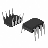
8-DIP
Functions
Differential Amplifier
Level Comparator
Latch Circuit
8-SOP
Ordering Information
Part Number Operating Temperature Range
KA2803B
-25 to +80°C
© 2000 Fairchild Semiconductor Corporation
KA2803B • Rev. 1.0.8
Package
8-Lead, Dual Inline Package (DIP)
Packing Method
Tube
www.fairchildsemi.com
KA2803B — Earth Leakage Detector
January 2014
�KA2803B — Earth Leakage Detector
Block Diagram
Figure 1. Block Diagram
Application Circuit
Figure 3. Half-Wave Application Circuit
Figure 2. Full-Wave Application Circuit
Application Information
used to protect the earth leakage detector IC
(KA2803B). The range of RP is from several hundred
Ω to several kΩ.
(Refer to full-wave application circuit in Figure 2)
Figure 2 shows the KA2803B connected in a typical
leakage current detector system. The power is applied
to the VCC terminal (Pin 8) directly from the power line.
The resistor RS and capacitor CS are chosen so that Pin
8 voltage is at least 12 V. The value of CS is
recommended above 1 µF.
Capacitor C1 is for the noise canceller and a standard
value of C1 is 0.047 µF. Capacitor C2 is also a noise
canceller capacitance, but it is not usually used.
When high noise is present, a 0.047 µF capacitor may
be connected between Pins 6 and 7. The amplified
signal finally appears at the Pin 7 with pulse signal
through the internal latch circuit of the KA2803B. This
signal drives the gate of the external SCR, which
energizes the trip coil, which opens the circuit breaker.
The trip time of the breaker is determined by capacitor
C3 and the mechanism breaker. This capacitor should
be selected under 1µF to satisfy the required trip time.
The full-wave bridge supplies power to the KA2803B
during both the positive and negative half cycles of the
line voltage. This allows the hot and neutral lines to be
interchanged.
If the leakage current is at the load, it is detected by the
zero current transformer (ZCT). The output voltage
signal of ZCT is amplified by the differential amplifier of
the KA2803B internal circuit and appears as a half-cycle
sine wave signal referred to input signal at the output of
the amplifier. The amplifier closed-loop gain is fixed
about 1000 times with internal feedback resistor to
compensate for zero current transformer (ZCT)
variations. The resistor RL should be selected so that
the breaker satisfies the required sensing current. The
protection resistor RP is not usually used when high
current is injected at the breaker; this resistor should be
© 2000 Fairchild Semiconductor Corporation
KA2803B • Rev. 1.0.8
www.fairchildsemi.com
2
�Stresses exceeding the absolute maximum ratings may damage the device. The device may not function or be
operable above the recommended operating conditions and stressing the parts to these levels is not recommended.
In addition, extended exposure to stresses above the recommended operating conditions may affect device reliability.
The absolute maximum ratings are stress ratings only.
Symbol
Parameter
Min.
Max.
Unit
VCC
Supply Voltage
20
V
ICC
Supply Current
8
mA
PD
Power Dissipation
300
mW
TL
Lead Temperature, Soldering 10 Seconds
260
°C
TA
Operation Temperature Range
-25
+80
°C
Storage Temperature Range
-65
+150
°C
TSTG
KA2803B — Earth Leakage Detector
Absolute Maximum Ratings
Electrical Characteristics
TA = -25°C to +80°C unless otherwise specified.
Symbol
ICC
VT
Parameter
Supply Current 1
Trip Voltage
Conditions
Test
Circuit
Min.
Typ.
Max.
Figure 4
300
400
530
TA= -25°C
VCC=12V
VR=OPEN
VI=2 V
TA= +25°C
580
TA= +80°C
VCC=16 V,
VR=2 V~2.02 V, VI=2
IO
VSCON
µA
480
Figure 5
Note 1
IO(D)
Units
14
16
18
12.5
14.2
17.0
mV
(ms)
Differential Amplifier Current
Current 1
VCC=16 V, VR~VI=30 mV,
VOD=1.2 V
Figure 7
-12
20
-30
Differential Amplifier Current
Current 2
VCC=16 V, VOD=0.8 V,VR,
VI Short=VP
Figure 8
17
27
37
VSC=1.4 V, TA= -25°C
VOS=0.8 V, TA= +25°C
VCC=16.0 V
TA= +80°C
200
400
800
Output Current
Figure 9
200
400
800
100
300
600
VCC=16 V
Figure 10
0.7
1.0
1.4
V
Latch-On Voltage
µA
µA
ISCON
Latch Input Current
VCC=16 V
Figure 11
-13
-7
-1
µA
IOSL
Output Low Current
VCC=12 V, VOSL=0.2 V
Figure 12
200
800
1400
µA
VIDC
Differential Input Clamp Voltage
VCC=16 V, IIDC=100 mA
Figure 13
0.4
1.2
2.0
V
VSM
Maximum Current Voltage
ISM=7 mA
Figure 14
20
24
28
V
IS2
Supply Current 2
VCC=12.0 V, VOSL=0.6 V
Figure 15
200
400
900
µA
Figure 16
7
8
9
V
Figure 17
2
3
4
ms
VOS=12.0 V
VSOFF
Latch-Off Supply Voltage
VSC=1.8 V
IIDC=100.0 mA
tON
Response Time
VCC=16 V, VR-VI=0.3 V,
1 V


 工商网监
湘ICP备2023018690号
工商网监
湘ICP备2023018690号
