Test Procedure for the LB1939TGEVB Evaluation Board
For stepper motor control in constant voltage mode
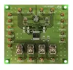
Please contact RFG1-terminal and RFG2-terminal and PGND-terminal.
Therefore R1 resistor and C4 capacitor is not mount evaluation board.
CURRENT PROBE
AMPLIFIER1
Osclloscope
PROBE
INPUT
OUTPUT
CHANNEL
1
2
3
4
Stepping Motor
Power supply 1
V
A
-
+
Logic generator
Power supply 2
A
V
CHANNEL
1
-
2
3
4
+
Table1: Required Equipment
Equipment
Power supply1
Power supply2
Logic generator
Oscilloscope
Current probe1
LB1909MC Evaluation Board
Stepper Motor
1/8/2014
Efficiency
12V-1A
10V-0.5A
200kHz
4 channel
5V-0.4A
1
www.onsemi.com
�Test Procedure:
1. Connect the test setup as shown above.
2. Set it according to the following guide.
[Supply Voltage]
VDD, VS (1.9V to 6.5V) : Power Supply for LSI
VIN (2.0 to 6.0V) : Logic “High” voltage for toggle switch
[Toggle Switch State] Upper Side: High (VIN)
Middle: Open, enable to external logic input
Lower Side: Low (GND)
[Operation Guide]
1. Initial Condition Setting: Set “Open” the toggle switches ENA , IN1 and IN2.
2. Power Supply: Supply DC voltage to VS and VDD and VIN.
3. Ready for Operation from Standby State: Turn “High” the ENA terminal toggle switch.
4. Motor Operation: Input the signal which is in condition to want to operate into IN1 and
IN2.
3. Check the IN1 , IN2 and OUT1 terminal voltage at scope CH1 , CH2 and CH3, and the output
current waveform at scope CH4.
Table2: Desired Results
INPUT
VCC=3.3V
VDD=3.3V,VIN=3.3V
ENA=H
IN1 , IN2=Full-step signal
OUTPUT
* Refer to the following waveform
Typical current waveform
LB1939T Full-Step(VCC=3.3V, 200pps)
IN1
IN2
(%)
100
I1
0
-100
100
I2
0
-100
1/8/2014
2
www.onsemi.com
�For stepper motor control in constant current mode
Evalboard is constant voltage drive.
If Eval board use constant current driving, Please Eval board changing below
It remove C3 capacitor and mount R1 and C4 parts.
Finally contact RFG-Io and PGND.
CURRENT PROBE
AMPLIFIER1
Osclloscope
PROBE
INPUT
OUTPUT
CHANNEL
1
2
3
4
Stepping Motor
Power supply 1
A
V
-
+
Logic generator
Power supply 2
A
V
CHANNEL
1
-
2
3
4
+
Table3: Required Equipment
Equipment
Power supply1
Power supply2
Logic generator
Oscilloscope
Current probe1
LB1909MC Evaluation Board
Stepper Motor
1/8/2014
Efficiency
12V-1A
10V-0.5A
200kHz
4 channel
5V-0.4A
3
www.onsemi.com
�Test Procedure:
1. Connect the test setup as shown above.
2. Set it according to the following guide.
[Supply Voltage]
VDD, VS (1.9V to 6.5V) : Power Supply for LSI
VIN (2.0 to 6.0V) : Logic “High” voltage for toggle switch
[Toggle Switch State] Upper Side: High (VIN)
Middle: Open, enable to external logic input
Lower Side: Low (GND)
[Operation Guide]
1. Initial Condition Setting: Set “Open” the toggle switches ENA , IN1 and IN2.
2. Power Supply: Supply DC voltage to VS and VDD and VIN.
3. Ready for Operation from Standby State: Turn “High” the ENA terminal toggle switch.
4. Motor Operation: Input the signal which is in condition to want to operate into IN1 and
IN2.
3. Check the IN1 , IN2 and OUT1 terminal voltage at scope CH1 , CH2 and CH3, and the output
current waveform at scope CH4.
Table4: Desired Results
INPUT
VCC=3.3V
VDD=3.3V,VIN=3.3V
ENA=H
IN1 , IN2=Full-step signal
OUTPUT
* Refer to the following waveform
Typical current waveform
LB1939T Full-Step(VCC=3.3V, 200pps)
IN1
IN2
(%)
100
I1
0
-100
100
I2
0
-100
1/8/2014
4
www.onsemi.com
�
很抱歉,暂时无法提供与“LB1939TGEVB”相匹配的价格&库存,您可以联系我们找货
免费人工找货