Formosa MS
Schottky Barrier Rectifier
MBR2040CT THRU MBR20200CT
List
List................................................................................................. 1
Package outline............................................................................... 2
Features.......................................................................................... 2
Mechanical data............................................................................... 2
Maximum ratings .............................................................................. 2
Electrical characteristics................................................................... 2
Rating and characteristic curves........................................................ 3
Pinning information........................................................................... 4
Marking........................................................................................... 4
Tube packing.................................................................................... 4
Suggested thermal profiles for soldering processes............................. 5
High reliability test capabilities........................................................... 6
http://www.formosams.com/
TEL:886-2-22696661
FAX:886-2-22696141
Document ID
Page 1
DS-222690
Issued Date
2008/02/10
Revised Date
2016/10/05
Revision
F
Page.
6
�Formosa MS
Schottky Barrier Rectifier
MBR2040CT THRU MBR20200CT
20A High Barrier Power Schottky
Rectifiers - 40V-200V
Features
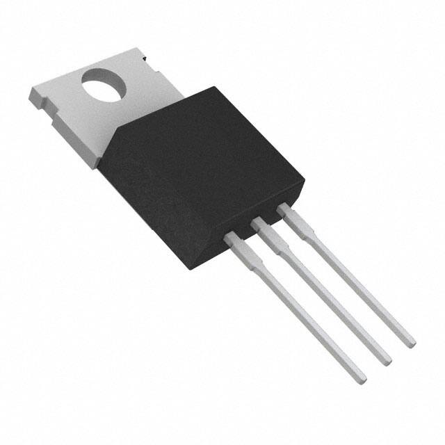
Package outline
• Low power loss, high efficiency.
• High current capability
• High surge capability.
• Guardring for overvoltage protection.
• Low stored charge majority carrier conduction
• Silicon epitaxial planar chip, metal silicon junction.
• Lead-free parts meet environmental standards of
•
TO-220AB
0.419(10.66)
0.387(9.85)
0.196(5.00)
0.163(4.16)
0.054(1.39)
0.045(1.15)
0.269(6.85)
0.226(5.75)
MIL-STD-19500 /228
Suffix "-H" indicates Halogen-free parts, ex. ΜΒR2040CT-H.
0.624(15.87)
0.548(13.93)
0.139(3.55)
MIN
1
2
3
Mechanical data
0.177(4.50)MAX
• Epoxy : UL94-V0 rated flame retardant
• Case : JEDEC TO-220AB molded plastic body over
0.038(0.96)
0.019(0.50)
0.50(12.70)MIN
passivated chip
• Lead : Axial leads, solderable per MIL-STD-202,
0.1(2.54)
0.025(0.65)MAX
Method 208 guranteed
• Polarity: As marked
• Mounting Position : Any
• Weight : Approximated 2.10 gram
Maximum ratings (AT
PIN 1
PIN 3
PIN 2
Dimensions in inches and (millimeters)
T A=25 oC unless otherwise noted)
PARAMETER
2040CT
MBR
2045CT
MBR
2050CT
MBR
2060CT
MBR
2080CT
MBR
20100CT
MBR
20150CT
MBR
20200CT
UNIT
SYMBOLS MBR
Maximum repetitive peak reverse voltage
VRRM
40
45
50
60
80
100
150
200
V
Maximum RMS voltage
VRMS
28
31.5
35
42
56
70
105
140
V
Maximum DC blocking voltage
VDC
40
45
50
60
80
100
150
200
V
Maximum average forward rectified current
Per device
IO
20
A
Peak forward surge current 8.3ms
single half sine-wave(JEDEC method)
IFSM
150
A
Operating junction temperature range
TJ
-55 to +150
Storage temperature range
TSTG
-65 to +175
Electrical characteristics (AT
PARAMETER
2040CT
VF
Maximum DC reverse current at T J =25°C
at rated DC blocking voltage at T J =125°C
IR
°C
T A=25 oC unless otherwise noted)
SYMBOLS MBR
Maximum forward voltage per leg at I F =10A
at I F =20A
°C
-55 to +175
MBR
2045CT
MBR
2050CT
0.65
0.84
MBR
2060CT
MBR
2080CT
0.75
0.85
MBR
20100CT
MBR
20200CT
MBR
20150CT
0.85
0.95
UNIT
0.92
1.00
0.05
10
V
V
mA
mA
0.01
10
Thermal characteristics
PARAMETER
SYMBOLS MBR
Typical thermal resistance
junction to case per leg
http://www.formosams.com/
TEL:886-2-22696661
FAX:886-2-22696141
2040CT
MBR
2045CT
MBR
2050CT
R θJC
MBR
2060CT
MBR
2080CT
MBR
20100CT
MBR
20150CT
MBR
20200CT
UNIT
2.0
°C/W
Document ID
Page 2
DS-222690
Issued Date
2008/02/10
Revised Date
2016/10/05
Revision
F
Page.
6
�FIG. 1 - FORWARD DERATING CURVE
12
MBR20150CT~
MBR20200CT
10
MBR2040CT~
MBR20100CT
8
6
4
2
SINGLE PHASE HALF WAVE 60Hz
RESISTIVE OR INDUCTIVE LOAD
0
0
25
50
75
100
125
150
175
PEAK FORWARD SURGE CURRENT,
AMPERES
AVERAGE FORWARD RECTIFIED
CURRENT, AMPERES
Rating and characteristic curves (MBR2040CT THRU MBR20200CT)
FIG. 2 - MAXIMUM NON-REPETITIVE FORWARD
SURGE CURRENT
150
125
100
50
25
0
1
10
100
CASE TEMPERATURE (°C)
NUMBER OF CYCLES AT 60Hz
FIG. 3 - TYPICAL REVERSE CHARACTERISTICS
FIG. 4 - TYPICAL FORWARD CHARACTERISTIC
PER LEG
100
INSTANTANEOUS FORWARD CURRENT
AMPERES
10.0
INSTANTANEOUS REVERSE CURRENT (mA)
75
TJ=125°C
1.0
TJ=100°C
0.1
0.01
MBR2040~45CT
MBR2050~60CT
MBR2080~100CT
MBR20150~200CT
10
1.0
TJ=25°C
0.001
0
20
40
60
80
100
PERAENT OR RATED VOLTAGE PEAK REVERSE VOLTAGE (%)
http://www.formosams.com/
TEL:886-2-22696661
FAX:886-2-22696141
0.1
0.1
0.3
Document ID
Page 3
0.5
0.7
0.9
1.1
INSTANTANEOUS FORWARD VOLTAGE,
VOLTS
DS-222690
Issued Date
2008/02/10
Revised Date
2016/10/05
Revision
F
Page.
6
�Formosa MS
Schottky Barrier Rectifier
MBR2040CT THRU MBR20200CT
Pinning information
Pin
Pin1
Pin2
Pin3
Simplified outline
anode
cathode
anode
1
2
Symbol
PIN 1
PIN 3
3
PIN 2
Marking
Type number
MBR2040CT
MBR2045CT
MBR2050CT
MBR2060CT
MBR2080CT
MBR20100CT
MBR20150CT
MBR20200CT
Marking code
MBR2040CT
MBR2045CT
MBR2050CT
MBR2060CT
MBR2080CT
MBR20100CT
MBR20150CT
MBR20200CT
Tube packing
PACKAGE
TO-220AB
TUBE
(pcs)
50
TUBE SIZE
(m/m)
525*32*7.5
BOX
(pcs)
INNER
BOX
(m/m)
1,000
555*150*40
http://www.formosams.com/
TEL:886-2-22696661
FAX:886-2-22696141
CARTON
SIZE
(m/m)
580*230*175
CARTON
(pcs)
5,000
APPROX.
GROSS WEIGHT
(kg)
15.0
Document ID
Page 4
DS-222690
Issued Date
2008/02/10
Revised Date
2016/10/05
Revision
F
Page.
6
�Formosa MS
Schottky Barrier Rectifier
MBR2040CT THRU MBR20200CT
Suggested thermal profiles for soldering processes
1.Lead free temperature profile wave-soldering
280
Peak soldering temperature not
to exceed 260ºC
260
240
220
Temperature(°C)
200
180
160
140
120
Peak
Max well
time 5 Max
100
80
Cool Down
Max gradient-4ºC/s
Suggested gradient - 2ºC/s or
less
60
40
20
Preheat
Max gradient 2ºC/s
0
0
20
40
60
80
100 120 140 160 180 200 220 240
Time(Sec)
http://www.formosams.com/
TEL:886-2-22696661
FAX:886-2-22696141
Document ID
Page 5
DS-222690
Issued Date
2008/02/10
Revised Date
2016/10/05
Revision
F
Page.
6
�Formosa MS
Schottky Barrier Rectifier
MBR2040CT THRU MBR20200CT
High reliability test capabilities
Item Test
Conditions
Reference
O
1. Solder Resistance
at 260 ± 5 C for 10 ± 2sec.
immerse body into solder 1/16"±1/32"
MIL-STD-750D
METHOD-2031
2. Solderability
at 245±5 OC for 5 sec.
MIL-STD-202F
METHOD-208
3. High Temperature Reverse Bias
V R=80% rate at T J=150 OC for 168 hrs.
MIL-STD-750D
METHOD-1038
4. Forward Operation Life
Rated average rectifier current at T A=25 OC for 500hrs.
MIL-STD-750D
METHOD-1027
T A = 25 OC, I F = I O
On state: power on for 5 min.
off state: power off for 5 min.
on and off for 500 cycles.
MIL-STD-750D
METHOD-1036
5. Intermittent Operation Life
6. Pressure Cooker
JESD22-A102
15P SIG at T A=121 OC for 4 hrs.
MIL-STD-750D
METHOD-1051
7. Temperature Cycling
-55 OC to +125 OC dwelled for 30 min.
and transferred for 5min. total 10 cycles.
8. Forward Surge
8.3ms single half sine-wave , one surge.
MIL-STD-750D
METHOD-4066-2
9. Humidity
at T A=85 OC, RH=85% for 1000hrs.
MIL-STD-750D
METHOD-1021
10. High Temperature Storage Life
at 175 OC for 1000 hrs.
MIL-STD-750D
METHOD-1031
http://www.formosams.com/
TEL:886-2-22696661
FAX:886-2-22696141
Document ID
Page 6
DS-222690
Issued Date
2008/02/10
Revised Date
2016/10/05
Revision
F
Page.
6
�
很抱歉,暂时无法提供与“MBR2045CTH”相匹配的价格&库存,您可以联系我们找货
免费人工找货