MJ11021(PNP)
MJ11022 (NPN)
Complementary Darlington
Silicon Power Transistors
Complementary Darlington Silicon Power Transistors are designed
for use as general purpose amplifiers, low frequency switching and
motor control applications.
15 AMPERE
COMPLEMENTARY
DARLINGTON POWER
TRANSISTORS
250 VOLTS, 175 WATTS
Features
• High dc Current Gain @ 10 Adc − hFE = 400 Min (All Types)
• Collector−Emitter Sustaining Voltage
VCEO(sus) = 250 Vdc (Min) − MJ11022, 21
• Low Collector−Emitter Saturation
= 1.0 V (Typ) @ IC = 5.0 A
= 1.8 V (Typ) @ IC = 10 A
100% SOA Tested @ VCE = 44 V
IC = 4.0 A
t = 250 ms
Pb−Free Packages are Available*
VCE(sat)
•
•
http://onsemi.com
NPN
PNP
COLLECTOR
CASE
COLLECTOR
CASE
BASE
1
BASE
1
MAXIMUM RATINGS (TJ = 25°C unless otherwise noted)
Symbol
Value
Unit
Collector−Emitter Voltage
VCEO
250
Vdc
Collector−Base Voltage
VCBO
250
Vdc
Emitter−Base Voltage
Rating
VEBO
50
Vdc
Collector Current − Continuous
− Peak (Note 1)
IC
15
30
Adc
Base Current
IB
0.5
Adc
Total Power Dissipation @ TC = 25°C
Derate Above 25°C
PD
175
1.16
W
W/°C
TJ, Tstg
– 65 to +175
− 65 to +200
°C
Operating and Storage Junction
Temperature Range
EMITTER 2
MJ11022
MARKING
DIAGRAM
2
Characteristic
Symbol
Max
Unit
RqJC
0.86
°C/W
Maximum ratings are those values beyond which device damage can occur.
Maximum ratings applied to the device are individual stress limit values (not
normal operating conditions) and are not valid simultaneously. If these limits are
exceeded, device functional operation is not implied, damage may occur and
reliability may be affected.
1. Pulse Test: Pulse Width = 5 ms, Duty Cycle ≤ 10%.
ORDERING INFORMATION
Device
MJ11021G
MJ11022
© Semiconductor Components Industries, LLC, 2008
September, 2008 − Rev. 3
1
MJ1102xG
AYYWW
MEX
MJ1102x = Device Code
x = 1 or 2
G
= Pb−Free Package
A
= Location Code
YY
= Year
WW
= Work Week
MEX
= Country of Orgin
MJ11021
*For additional information on our Pb−Free strategy and soldering details, please
download the ON Semiconductor Soldering and Mounting Techniques
Reference Manual, SOLDERRM/D.
1
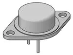
TO−204 (TO−3)
CASE 1−07
STYLE 1
THERMAL CHARACTERISTICS
Thermal Resistance, Junction−to−Case
EMITTER 2
MJ11021
MJ11022G
Package
Shipping
TO−3
100 Units/Tray
TO−3
(Pb−Free)
100 Units/Tray
TO−3
100 Units/Tray
TO−3
(Pb−Free)
100 Units/Tray
Publication Order Number:
MJ11021/D
�PD, POWER DISSIPATION (WATTS)
MJ11021(PNP)
MJ11022 (NPN)
RB and RC VARIED TO OBTAIN DESIRED CURRENT LEVELS
�D1 MUST BE FAST RECOVERY TYPE, e.g.:
��1N5825 USED ABOVE IB ≈ 100 mA
��MSD6100 USED BELOW IB ≈ 100 mA
200
RC
SCOPE
TUT
150
V2
APPROX
+12 V
100
0
50
V1
APPROX
-�8.0 V
0
VCC
100 V
RB
51
D1
≈ 10 K
≈ 8.0
+�4.0 V
25 ms
for td and tr, D1 is disconnected
and V2 = 0
tr, tf ≤ 10 ns
DUTY CYCLE = 1.0%
0
25
50
75
100
125
150
TC, CASE TEMPERATURE (°C)
175
200
For NPN test circuit reverse diode and voltage polarities.
Figure 1. Power Derating
Figure 2. Switching Times Test Circuit
ELECTRICAL CHARACTERISTICS (TC = 25_C unless otherwise noted)
Characteristic
Symbol
Min
Max
250
−
−
1.0
−
−
0.5
5.0
−
2.0
400
100
15,000
−
−
−
2.0
3.4
Unit
OFF CHARACTERISTICS
Collector−Emitter Sustaining Voltage (Note 1)
(IC = 0.1 Adc, IB = 0)
MJ11021, MJ11022
Collector Cutoff Current
(VCE = 125, IB = 0)
MJ11021, MJ11022
VCEO(sus)
ICEO
Collector Cutoff Current
(VCE = Rated VCB, VBE(off) = 1.5 Vdc)
(VCE = Rated VCB, VBE(off) = 1.5 Vdc, TJ = 150_C)
ICEV
Emitter Cutoff Current (VBE = 5.0 Vdc, IC = 0)
IEBO
Vdc
mAdc
mAdc
mAdc
ON CHARACTERISTICS (Note 1)
DC Current Gain
(IC = 10 Adc, VCE = 5.0 Vdc)
(IC = 15 Adc, VCE = 5.0 Vdc)
hFE
−
Collector−Emitter Saturation Voltage
(IC = 10 Adc, IB = 100 mA)
(IC = 15 Adc, IB = 150 mA)
VCE(sat)
Vdc
Base−Emitter On Voltage
IC = 10 A, VCE = 5.0 Vdc)
VBE(on)
−
2.8
Vdc
Base−Emitter Saturation Voltage
(IC = 15 Adc, IB = 150 mA)
VBE(sat)
−
3.8
Vdc
[hfe]
3.0
−
Mhz
−
−
400
600
75
−
DYNAMIC CHARACTERISTICS
Current−Gain Bandwidth Product
(IC = 10 Adc, VCE = 3.0 Vdc, f = 1.0 MHz)
Output Capacitance (VCB = 10 Vdc, IE = 0, f = 0.1 MHz)
MJ11022
MJ11021
Small−Signal Current Gain
(IC = 10 Adc, VCE = 3.0 Vdc, f = 1.0 kHz)
Cob
hfe
pF
−
SWITCHING CHARACTERISTICS
Characteristic
Symbol
Delay Time
Rise Time
Storage Time
(VCC = 100 V, IC = 10 A, IB = 100 mA
VBE(off) = 50 V) (See Figure 2)
Fall Time
1. Pulsed Test: Pulse Width = 300 ms, Duty Cycle v 2%.
http://onsemi.com
2
Typical
NPN
PNP
Unit
td
150
75
ns
tr
1.2
0.5
ms
ts
4.4
2.7
ms
tf
10.0
2.5
ms
�r(t), EFFECTIVE TRANSIENT THERMAL
RESISTANCE (NORMALIZED)
MJ11021(PNP)
1.0
0.7
0.5
MJ11022 (NPN)
D = 0.5
0.3
0.2
0.2
0.1
0.1
0.07
0.05
RqJC(t) = r(t) RqJC
RqJC(t) = 0.86°C/W MAX
D CURVES APPLY FOR POWER
PULSE TRAIN SHOWN
READ TIME AT t1
TJ(pk) - TC = P(pk) RqJC(t)
0.05
0.02
0.01
0.03
SINGLE PULSE
0.02
0.01
0.01
0.02
0.03 0.05
0.2
1.0
0.3 0.5
1.0
2.0
3.0 5.0
t, TIME (ms)
10
20
30
P(pk)
t1
t2
DUTY CYCLE, D = t1/t2
50
100
200 300
500
1000
Figure 3. Thermal Response
1.0�ms
0.5�ms
30
20
0.1 ms
10
5.0
3.0
2.0
1.0
0.5
0.3
0.2
0
3.0
IC, COLLECTOR CURRENT (AMPS)
IC, COLLECTOR CURRENT (AMPS)
30
5.0�ms
dc
TJ = 175°C
SECOND BREAKDOWN LIMIT
BONDING WIRE LIMIT
THERMAL LIMITATION @ TC = 25°C
SINGLE PULSE
5.0 7.0
10
20
30 50
70
L = 200 mH
IC/IB1 ≥ 50
TC = 25°C
VBE(off) 0 - 5.0 V
RBE = 47 W
DUTY CYLE = 10%
20
10
0
100 150 200
0 20
VCE, COLLECTOR-EMITTER VOLTAGE (VOLTS)
Figure 4. Maximum Rated Forward Bias Safe
Operating Area (FBSOA)
60
100
140
180
220
VCE, COLLECTOR-EMITTER VOLTAGE (VOLTS)
260
Figure 5. Maximum RBSOA, Reverse Bias Safe
Operating Area
REVERSE BIAS
FORWARD BIAS
For inductive loads, high voltage and high current must be
sustained simultaneously during turn−off, in most cases,
with the base to emitter junction reverse biased. Under these
conditions the collector voltage must be hold to a safe level
at or below a specific value of collector current. This can be
accomplished by several means such as active clamping, RC
snubbing, load line shaping, etc. The safe level for these
devices is specified as Reverse Bias Safe Operating Area
and represents the voltage−current conditions during
reverse biased turn−off. This rating is verified under
clamped conditions so that the device is never subjected to
an avalanche mode. Figure 5 gives ROSOA characteristics.
There are two limitations on the power handling ability of
a transistor average junction temperature and second
breakdown. Safe operating area curves indicate IC − VCE
limits of the transistor that must be observed for reliable
operation, i.e., the transistor must not be subjected to greater
dissipation than the curves indicate.
The data of Figure 4 is based on TJ(pk) = 175_C, TC is
variable dependIng on conditions. Second breakdown pulse
limits are valid for duty cycles to 10% provided TJ(pk)
v 175_C. TJ(pk) may be calculated from the data in
Figure 3. At high case temperatures thermal limitations will
reduce the power that can be handled to values less than the
limitations imposed by second breakdown.
http://onsemi.com
3
�MJ11021(PNP)
MJ11022 (NPN)
PNP
NPN
30,000
20,000
VCE = 5.0 Vdc
TJ = 150°C
hFE, DC CURRENT GAIN
hFE, DC CURRENT GAIN
10,000
7000
5000
3000
2000
TJ = 25°C
1000
700
500
TJ = - 55°C
300
VCE = 5.0 Vdc
TJ = 150°C
10,000
7000
5000
TJ = 25°C
3000
2000
TJ = - 55°C
1000
700
500
200
100
0.2
0.3
0.5 0.7 1.0
2.0 3.0
5.0 7.0
IC, COLLECTOR CURRENT (A)
300
0.2 0.3
15 20
10
0.5 0.7 1.0
2.0 3.0
5.0 7.0
IC, COLLECTOR CURRENT (A)
10
15 20
Figure 6. DC Current Gain
NPN
IC = 15 A
VCE , COLLECTOR-EMITTER VOLTAGE (VOLTS)
VCE , COLLECTOR-EMITTER VOLTAGE (VOLTS)
PNP
4.0
TJ = 25°C
3.5
IC = 10 A
3.0
IC = 5.0 A
2.5
2.0
1.5
1.0
0.5
0.5 0.7 1.0
2.0 3.0 5.0 7.0 10 20 30 50 70 100 200 300 500
IB, BASE CURRENT (mA)
4.0
IC = 15 A
3.5
TJ = 25°C
IC = 10 A
3.0
IC = 5.0 A
2.5
2.0
1.5
1.0
0.5
0.5 0.7 1.0
2.0 3.0 5.0 7.0 10 20 30 50 70 100 200 300 500
IB, BASE CURRENT (mA)
Figure 7. Collector Saturation Region
PNP
NPN
4.0
3.5
4.0
3.5
TJ = 25°C
VOLTAGE (VOLTS)
VOLTAGE (VOLTS)
TJ = 25°C
3.0
2.5
2.0
1.5
1.0
0.5
0.1
VBE(sat) @ IC/IB = 100
VBE @ VCE = 5.0 V
2.0 3.0 5.0 7.0 10
2.5
2.0
1.5
VBE(sat) @ IC/IB = 100
1.0
VCE(sat) @ IC/IB = 100
0.2 0.3 0.5 0.7 1.0
3.0
20 30
50
0.5
0.1
70
VBE @ VCE = 5.0 V
0.2 0.3 0.5 0.7 1.0
COLLECTOR CURRENT (AMPS)
VCE(sat) @ IC/IB = 100
2.0 3.0 5.0 7.0 10
COLLECTOR CURRENT (AMPS)
Figure 8. “On” Voltages
http://onsemi.com
4
20 30
50
�MECHANICAL CASE OUTLINE
PACKAGE DIMENSIONS
TO−204 (TO−3)
CASE 1−07
ISSUE Z
DATE 05/18/1988
SCALE 1:1
A
N
NOTES:
1. DIMENSIONING AND TOLERANCING PER ANSI
Y14.5M, 1982.
2. CONTROLLING DIMENSION: INCH.
3. ALL RULES AND NOTES ASSOCIATED WITH
REFERENCED TO-204AA OUTLINE SHALL APPLY.
C
−T−
E
D
K
2 PL
0.13 (0.005)
U
T Q
M
M
Y
DIM
A
B
C
D
E
G
H
K
L
N
Q
U
V
M
−Y−
L
V
SEATING
PLANE
2
H
G
B
M
T Y
1
−Q−
0.13 (0.005)
INCHES
MIN
MAX
1.550 REF
--1.050
0.250
0.335
0.038
0.043
0.055
0.070
0.430 BSC
0.215 BSC
0.440
0.480
0.665 BSC
--0.830
0.151
0.165
1.187 BSC
0.131
0.188
MILLIMETERS
MIN
MAX
39.37 REF
--26.67
6.35
8.51
0.97
1.09
1.40
1.77
10.92 BSC
5.46 BSC
11.18
12.19
16.89 BSC
--21.08
3.84
4.19
30.15 BSC
3.33
4.77
M
STYLE 1:
PIN 1. BASE
2. EMITTER
CASE: COLLECTOR
STYLE 2:
PIN 1. BASE
2. COLLECTOR
CASE: EMITTER
STYLE 3:
PIN 1. GATE
2. SOURCE
CASE: DRAIN
STYLE 4:
PIN 1. GROUND
2. INPUT
CASE: OUTPUT
STYLE 6:
PIN 1. GATE
2. EMITTER
CASE: COLLECTOR
STYLE 7:
PIN 1. ANODE
2. OPEN
CASE: CATHODE
STYLE 8:
PIN 1. CATHODE #1
2. CATHODE #2
CASE: ANODE
STYLE 9:
PIN 1. ANODE #1
2. ANODE #2
CASE: CATHODE
STYLE 5:
PIN 1. CATHODE
2. EXTERNAL TRIP/DELAY
CASE: ANODE
ON Semiconductor and
are trademarks of Semiconductor Components Industries, LLC (SCILLC). SCILLC reserves the right to make changes
without further notice to any products herein. SCILLC makes no warranty, representation or guarantee regarding the suitability of its products for any particular
purpose, nor does SCILLC assume any liability arising out of the application or use of any product or circuit, and specifically disclaims any and all liability,
including without limitation special, consequential or incidental damages. “Typical” parameters which may be provided in SCILLC data sheets and/or
specifications can and do vary in different applications and actual performance may vary over time. All operating parameters, including “Typicals” must be
validated for each customer application by customer’s technical experts. SCILLC does not convey any license under its patent rights nor the rights of others.
SCILLC products are not designed, intended, or authorized for use as components in systems intended for surgical implant into the body, or other applications
intended to support or sustain life, or for any other application in which the failure of the SCILLC product could create a situation where personal injury or
death may occur. Should Buyer purchase or use SCILLC products for any such unintended or unauthorized application, Buyer shall indemnify and hold
SCILLC and its officers, employees, subsidiaries, affiliates, and distributors harmless against all claims, costs, damages, and expenses, and reasonable
attorney fees arising out of, directly or indirectly, any claim of personal injury or death associated with such unintended or unauthorized use, even if such claim
alleges that SCILLC was negligent regarding the design or manufacture of the part. SCILLC is an Equal Opportunity/Affirmative Action Employer.
© Semiconductor Components Industries, LLC, 2000
January, 2000 − Rev. 07Z
1
Case Outline Number:
1
�onsemi,
, and other names, marks, and brands are registered and/or common law trademarks of Semiconductor Components Industries, LLC dba “onsemi” or its affiliates
and/or subsidiaries in the United States and/or other countries. onsemi owns the rights to a number of patents, trademarks, copyrights, trade secrets, and other intellectual property.
A listing of onsemi’s product/patent coverage may be accessed at www.onsemi.com/site/pdf/Patent−Marking.pdf. onsemi reserves the right to make changes at any time to any
products or information herein, without notice. The information herein is provided “as−is” and onsemi makes no warranty, representation or guarantee regarding the accuracy of the
information, product features, availability, functionality, or suitability of its products for any particular purpose, nor does onsemi assume any liability arising out of the application or use
of any product or circuit, and specifically disclaims any and all liability, including without limitation special, consequential or incidental damages. Buyer is responsible for its products
and applications using onsemi products, including compliance with all laws, regulations and safety requirements or standards, regardless of any support or applications information
provided by onsemi. “Typical” parameters which may be provided in onsemi data sheets and/or specifications can and do vary in different applications and actual performance may
vary over time. All operating parameters, including “Typicals” must be validated for each customer application by customer’s technical experts. onsemi does not convey any license
under any of its intellectual property rights nor the rights of others. onsemi products are not designed, intended, or authorized for use as a critical component in life support systems
or any FDA Class 3 medical devices or medical devices with a same or similar classification in a foreign jurisdiction or any devices intended for implantation in the human body. Should
Buyer purchase or use onsemi products for any such unintended or unauthorized application, Buyer shall indemnify and hold onsemi and its officers, employees, subsidiaries, affiliates,
and distributors harmless against all claims, costs, damages, and expenses, and reasonable attorney fees arising out of, directly or indirectly, any claim of personal injury or death
associated with such unintended or unauthorized use, even if such claim alleges that onsemi was negligent regarding the design or manufacture of the part. onsemi is an Equal
Opportunity/Affirmative Action Employer. This literature is subject to all applicable copyright laws and is not for resale in any manner.
PUBLICATION ORDERING INFORMATION
LITERATURE FULFILLMENT:
Email Requests to: orderlit@onsemi.com
onsemi Website: www.onsemi.com
◊
TECHNICAL SUPPORT
North American Technical Support:
Voice Mail: 1 800−282−9855 Toll Free USA/Canada
Phone: 011 421 33 790 2910
Europe, Middle East and Africa Technical Support:
Phone: 00421 33 790 2910
For additional information, please contact your local Sales Representative
�