MT9P031
1/2.5-Inch 5 Mp CMOS
Digital Image Sensor
General Description
www.onsemi.com
The ON Semiconductor MT9P031 is a 1/2.5−inch CMOS
active−pixel digital image sensor with an active imaging pixel array of
2592 H x 1944 V. It incorporates sophisticated camera functions
on−chip such as windowing, column and row skip mode, and snapshot
mode. It is programmable through a simple two−wire serial interface.
The 5 Mp CMOS image sensor features ON Semiconductor’s
breakthrough low−noise CMOS imaging technology that achieves
CCD image quality (based on signal−to−noise ratio and low−light
sensitivity) while maintaining the inherent size, cost, and integration
advantages of CMOS.
Applications
Value
Optical Format
1/2.5-inch (4:3)
Active Imager Size
5.70 mm (H) x 4.28 mm (V)
7.13 mm Diagonal
Active Pixels
2592 H x 1944 V
Pixel Size
2.2 x 2.2 μm
Color Filter Array
RGB Bayer Pattern
Shutter Type
Global Reset Release (GRR),
Snapshot Only
Electronic Rolling Shutter (ERS)
Maximum Data Rate / Pixel Clock
96 Mp/s at 96 MHz (2.8 V I/O)
48 Mp/s at 48 MHz (1.8 V I/O)
Frame Rate
Programmable up to 14 fps
HDTV (640 x 480,
with binning)
Programmable up to 53 fps
12-bit, On-chip
Responsivity
1.4 V/lux-sec (550 nm)
Pixel Dynamic Range
70.1 dB
SNRMAX
38.1 dB
I/O
1.7−3.1 V
Digital
1.7−1.9 V (1.8 V Nominal)
Analog
2.6−3.1 V (2.8 V Nominal)
•
•
•
•
•
Full Resolution
ADC Resolution
Supply Voltage
ORDERING INFORMATION
See detailed ordering and shipping information on page 2 of
this data sheet.
Table 1. KEY PERFORMANCE PARAMETERS
Parameter
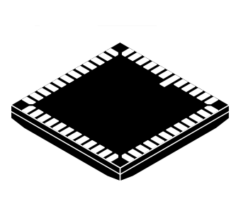
ILCC48 10x10
CASE 847AA
•
Features
•
•
•
•
•
•
•
•
Power Consumption
381 mW at 14 fps Full Resolution
Operating Temperature
–30°C to +70°C
Packaging
48-pin iLCC, Die
•
•
•
•
•
© Semiconductor Components Industries, LLC, 2006
January, 2017 − Rev. 10
1
High Resolution Network Cameras
Wide FOV Cameras
720 P–60 fps Cameras
Dome Cameras with Electronic Pan, Tile,
and Zoom
Hybrid Video Cameras with High
Resolution Stills
Detailed Feature Extraction for Smart
Cameras
High Frame Rate
Superior Low-light Performance
Low Dark Current
Global Reset Release, which Starts the
Exposure of All Rows Simultaneously
Bulb Exposure Mode, for Arbitrary
Exposure Times
Snapshot Mode to Take Frames on Demand
Horizontal and Vertical Mirror Image
Column and row skip modes to reduce
image size without reducing field−of−view
(FOV)
Column and Row Binning Modes to
Improve Image Quality when Resizing
Simple Two-wire Serial Interface
Programmable Controls: Gain, Frame Rate,
Frame Size, Exposure
Automatic Black Level Calibration
On-chip Phase-Locked Loop (PLL)
Publication Order Number:
MT9P031/D
�MT9P031
ORDERING INFORMATION
Table 2. AVAILABLE PART NUMBERS
Part Number
Product Description
Orderable Product Attribute Description
MT9P031D00STCC18BC1−200
5 MP 1/3” CIS
Die Sales, 200mm Thickness
MT9P031D00STMC18BC1−200
5 MP 1/3” CIS
Die Sales, 200mm Thickness
MT9P031I12STC−DP
5 MP 1/3” CIS
Dry Pack with Protective Film
MT9P031I12STC−DR
5 MP 1/3” CIS
Dry Pack without Protective Film
MT9P031I12STC−DR1
5 MP 1/3” CIS
Dry Pack Single Tray without Protective Film
MT9P031I12STC−TP
5 MP 1/3” CIS
Tape & Reel with Protective Film
MT9P031I12STM−DP
5 MP 1/3” CIS
Dry Pack with Protective Film
MT9P031I12STM−DP1
5 MP 1/3” CIS
Dry Pack Single Tray with Protective Film
MT9P031I12STM−DR
5 MP 1/3” CIS
Dry Pack without Protective Film
MT9P031I12STM−DR1
5 MP 1/3” CIS
Dry Pack Single Tray without Protective Film
DESCRIPTION
The MT9P031 sensor can be operated in its default mode
or programmed by the user for frame size, exposure, gain
setting, and other parameters. The default mode outputs a
full resolution image at 14 frames per second (fps).
An on−chip analog−to−digital converter (ADC) provides
12 bits per pixel. FRAME_VALID (FV) and LINE_VALID
(LV) signals are output on dedicated pins, along with a pixel
clock that is synchronous with valid data.
The MT9P031produces extraordinarily clear, sharp
digital pictures, and its ability to capture both continuous
video and single frames makes it the perfect choice for a
wide range of consumer and industrial applications,
including cell phones, digital still cameras, digital video
cameras, and PC cameras..
FUNCTIONAL OVERVIEW
The MT9P031 is a progressive−scan sensor that generates
a stream of pixel data at a constant frame rate. It uses an
on−chip, phase−locked loop (PLL) to generate all internal
clocks from a single master input clock running between
6 and 27 MHz. The maximum pixel rate is 96 Mp/s,
corresponding to a clock rate of 96 MHz. Figure 1 illustrates
a block diagram of the sensor.
Array Control
TRIGGER
Pixel Array
EXTCLK
RESET_BAR
STANDBY_BAR
OE
Output
2752H x 2004V
Serial
Interface
Analog Signal Chain
Data Path
SCLK
S DATA
SADDR
PIXCLK
DOUT [11:0]
LV
FV
STROBE
Figure 1. Block Diagram
and then reading each row in turn. In the time interval
between resetting a row and reading that row, the pixels in
the row integrate incident light. The exposure is controlled
by varying the time interval between reset and readout. Once
a row has been read, the data from the columns is sequenced
User interaction with the sensor is through the two−wire
serial bus, which communicates with the array control,
analog signal chain, and digital signal chain. The core of the
sensor is a 5 Mp active−pixel array. The timing and control
circuitry sequences through the rows of the array, resetting
www.onsemi.com
2
�MT9P031
through an analog signal chain (providing offset correction
and gain), and then through an ADC. The output from the
ADC is a 12−bit value for each pixel in the array. The ADC
output passes through a digital processing signal chain
(which provides further data path corrections and applies
digital gain). The pixel data are output at a rate of up to
96 Mp/s, in addition to frame and line synchronization
signals.
VDD_PLL
VAA_PIX
VAA
VDD
VDD_IO
1.0kΩ
1.5kΩ1
1.5kΩ1
VDD_IO 2,3 VDD2,3 VAA2,3
SADDR
RESET_BAR
STANDBY_BAR
DOUT [11:0]
PIXCLK
FV
LV
STROBE
1μF
SCLK
S DATA
TRIGGER
From
controller
Master
clock
To
controller
EXTCLK
TEST
AGND3
RSVD
DGND3
OE
Figure 2. Typical Configuration (Connection)
48
48
47
46
45
DOUT 9
1
DOUT 10
2
DOUT 11
A GND
3
DGND
TEST
4
VDD
SCLK
5
VAA_PIX
SDATA
6
VAA_PIX
RSVD
Notes:
1. A resistor value of 1.5 kΩ is recommended, but may be greater for slower two-wire speed.
2. All power supplies should be adequately decoupled.
3. All DGND pins must be tied together, as must all AGND pins, all VDD_IO pins, and all VDD pins.
44
43
FRAME_VALID
7
42
DOUT8
LINE_VALID
8
41
DOUT7
9
40
DOUT6
DGND
10
39
VDD_IO
VDD_ IO
11
38
DOUT5
VDD
12
37
DOUT4
DOUT3
STROBE
OE
17
PIXCLK
NC
18
31
EXTCLK
19
20
21
22
23
24
25
26
27
28
29
30
NC
DOUT0
32
NC
33
NC
16
NC
RESET_BAR
DGND
DOUT1
VDD_PLL
34
VAA
15
VAA
DOUT2
TRIGGER
AGND
35
TEST
14
TEST
13
STANDBY_BAR
NC
SADDR
36
Figure 3. 48-Pin iLCC 10 x 10 Package Pinout Diagram (Top View)
www.onsemi.com
3
�MT9P031
Table 3. PIN DESCRIPTION
Name
Type
RESET_BAR
Input
When LOW, the MT9P031 asynchronously resets. When driven HIGH,
it resumes normal operation with all configuration registers set to factory
defaults.
Description
EXTCLK
Input
External input clock.
SCLK
Input
Serial clock. Pull to VDD_IO with a 1.5 kΩ resistor.
OE
Input
When HIGH, the PIXCLK, DOUT, FV, LV, and STROBE outputs enter a High-Z.
When driven LOW, normal operation resumes.
STANDBY_BAR
Input
Standby. When LOW, the chip enters a low-power standby mode. It resumes
normal operation when the pin is driven HIGH.
TRIGGER
Input
Snapshot trigger. Used to trigger one frame of output in snapshot modes,
and to indicate the end of exposure in bulb exposure modes.
SADDR
Input
Serial address. When HIGH, the MT9P031 responds to device ID (BA)H.
When LOW, it responds to serial device ID (90)H.
SDATA
I/O
PIXCLK
Output
Pixel clock. The DOUT, FV, LV, and STROBE outputs should be captured on the
falling edge of this signal.
DOUT[11:0]
Output
Pixel data. Pixel data is 12-bit. MSB (DOUT11) through LSB (DOUT0) of each
pixel, to be captured on the falling edge of PIXCLK.
FRAME_VALID
Output
Frame valid. Driven HIGH during active pixels and horizontal blanking of each
frame and LOW during vertical blanking.
LINE_VALID
Output
Line valid. Driven HIGH with active pixels of each line and LOW during
blanking periods.
STROBE
Output
Snapshot strobe. Driven HIGH when all pixels are exposing in snapshot
modes.
VDD
Supply
Digital supply voltage. Nominally 1.8 V.
VDD_IO
Supply
IO supply voltage. Nominally 1.8 or 2.8 V.
DGND
Supply
Digital ground.
VAA
Supply
Analog supply voltage. Nominally 2.8 V.
VAA_PIX
Supply
Pixel supply voltage. Nominally 2.8 V, connected externally to VAA.
Serial data. Pull to VDD_IO with a 1.5 kΩ resistor.
AGND
Supply
Analog ground.
VDD_PLL
Supply
PLL supply voltage. Nominally 2.8 V, connected externally to VAA.
TEST
−
Tie to AGND for normal device operation (factory use only).
RSVD
−
Tie to DGND for normal device operation (factory use only).
NC
−
No connect.
www.onsemi.com
4
�MT9P031
PIXEL DATA FORMAT
Pixel Array Structure
The MT9P031 pixel array consists of a 2752−column by
2004−row matrix of pixels addressed by column and row.
The address (column 0, row 0) represents the upper−right
corner of the entire array, looking at the sensor, as shown in
Figure 4.
The array consists of a 2592−column by 1944−row active
region in the center representing the default output image,
surrounded by a boundary region (also active), surrounded
by a border of dark pixels (see Table 4 and Table 5). The
boundary region can be used to avoid edge effects when
doing color processing to achieve a 2592 x 1944 result
image, while the optically black column and rows can be
used to monitor the black level.
Pixels are output in a Bayer pattern format consisting of
four “colors”−GreenR, GreenB, Red, and Blue (Gr, Gb, R,
B)−representing three filter colors. When no mirror modes
are enabled, the first row output alternates between Gr and
R pixels, and the second row output alternates between B
and Gb pixels. The Gr and Gb pixels have the same color
filter, but they are treated as separate colors by the data path
and analog signal chain.
Table 4. PIXEL TYPE BY COLUMN
Column
Pixel Type
0–9
Dark (10)
10–15
Active boundary (6)
16–2607
Active image (2592)
2608–2617
Active boundary (10)
2618–2751
Dark (134)
Table 5. PIXEL TYPE BY ROW
Column
Pixel Type
0–49
Dark (50)
50–53
Active boundary (4)
54–1997
Active image (1944)
1998–2001
Active boundary (3)
2002–2003
Dark (2)
(0,0)
50 black rows
4
(16,54)
Active Image
134 black columns
10
2592 x 1944
active pixels
6
10 black columns
4
2 black rows
(2751, 2003)
Figure 4. Pixel Array Description
column readout direction
..
black pixels
.
Gr R Gr R Gr R Gr
row
readout
direction
First clear
pixel (10,50)
B Gb B Gb B Gb B
... Gr R Gr R Gr R Gr
B Gb B Gb B Gb B
Gr R Gr R Gr R Gr
B Gb B Gb B Gb B
..
.
Figure 5. Pixel Color Pattern Detail (Top Right Corner)
www.onsemi.com
5
�MT9P031
Default Readout Order
When the sensor is imaging, the active surface of the
sensor faces the scene as shown in Figure 5. When the image
is read out of the sensor, it is read one row at a time, with the
rows and columns sequenced as shown in Figure 6.
By convention, the sensor core pixel array is shown with
pixel (0,0) in the top right corner (see Figure 4). This reflects
the actual layout of the array on the die. Also, the first pixel
data read out of the sensor in default condition is that of pixel
(16, 54).
Lens
Scene
Sensor (rear view)
Row
Readout
Order
Column Readout Order Pixel (0,0)
Figure 6. Imaging a Scene
Output Data Format (Default Mode)
and vertical blanking, as shown in Figure 7. LV is HIGH
during the shaded region of the figure. FV timing is
described in “Output Data Timing”.
The MT9P031 image data is read out in a progressive
scan. Valid image data is surrounded by horizontal blanking
P0,0 P0,1 P0,2 .....................................P0,n−1 P0,n
P1,0 P1,1 P1,2 .....................................P1,n−1 P1,n
00 00 00 .................. 00 00 00
00 00 00 .................. 00 00 00
VALID IMAGE
HORIZONTAL
BLANKING
Pm−1,0 Pm−1,1 .....................................Pm−1,n−1Pm−1,n
Pm,0 Pm,1 .....................................Pm,n−1 Pm,n
00 00 00 ..................................... 00 00 00
00 00 00 ..................................... 00 00 00
00 00 00 .................. 00 00 00
00 00 00 .................. 00 00 00
00 00 00 .................. 00 00 00
00 00 00 .................. 00 00 00
VERTICAL/HORIZONTAL
BLANKING
VERTICAL BLANKING
00 00 00 ..................................... 00 00 00
00 00 00 ..................................... 00 00 00
00 00 00 .................. 00 00 00
00 00 00 .................. 00 00 00
Figure 7. Spatial Illustration of Image Readout
www.onsemi.com
6
�MT9P031
Readout Sequence
Columns are read out in the following order:
1. Dark columns:
If either Show_Dark_Columns or Row_BLC is
set, dark columns on the left side of the image are
read out followed by those on the right side. The
set of columns read is shown in Table 7. The
Column_Skip setting is ignored for the dark
columns.
If neither Show_Dark_Columns nor Row_BLC is
set, no dark columns are read, allowing all
columns to be part of the active image. This does
not change the row time, as WDC is included in the
vertical blank period.
2. Active image:
The columns defined by column start, column size,
bin, skip, and column mirror settings are read out.
If this set of columns includes the columns read
out above, these columns are resampled, meaning
the data is invalid.
Typically, the readout window is set to a region including
only active pixels. The user has the option of reading out
dark regions of the array, but if this is done, consideration
must be given to how the sensor reads the dark regions for
its own purposes.
Rows are read from the array in the following order:
1. Dark rows:
If Show_Dark_Rows is set, or if Manual_BLC is
clear, dark rows on the top of the array are read
out. The set of rows sampled are adjusted based on
the Row_Bin setting such that there are 8 rows
after binning, as shown in the Table 6. The
Row_Skip setting is ignored for the dark row
region.
If Show_Dark_Rows is clear and Manual_BLC is
set, no dark rows are read from the array as part of
this step, allowing all rows to be part of the active
image. This does not change the frame time, as
HDR is included in the vertical blank period.
2. Active image:
The rows defined by the row start, row size, bin,
skip, and row mirror settings are read out. If this
set of rows includes rows read out above, those
rows are resampled, meaning that the data is
invalid.
Table 7. DARK COLUMNS SAMPLED AS
A FUNCTION OF COLUMN_BIN
Column_Bin
WDC (Dark Columns After Binning)
0
80
1
40
3
20
Table 6. DARK ROWS SAMPLED AS A FUNCTION
OF ROW_BIN
Row_Bin
HDR (Dark Rows After Binning)
0
8
1
8
3
8
www.onsemi.com
7
�MT9P031
OUTPUT DATA TIMING
The output images are divided into frames, which are
further divided into lines. By default, the sensor produces
1944 rows of 2592 columns each. The FV and LV signals
indicate the boundaries between frames and lines,
respectively. PIXCLK can be used as a clock to latch the
data. For each PIXCLK cycle, one 12−bit pixel datum
outputs on the DOUT pins. When both FV and LV are
asserted, the pixel is valid. PIXCLK cycles that occur when
FV is negated are called vertical blanking. PIXCLK cycles
that occur when only LV is negated are called horizontal
blanking.
PIXCLK
FV
LV
D OUT [11:0]
P0
Vertical Blanking
Horiz Blanking
P1
P2
P3
P4
Valid Image Data
Pn
Horiz Blanking
Vertical Blanking
Figure 8. Default Pixel Output Timing
LV and FV
will be extended back to include them; in this case, the first
pixel of the active image still occurs at the same position
relative to the leading edge of FV. Normally, LV will only be
asserted if FV is asserted; this is configurable as described
below.
The timing of the FV and LV outputs is closely related to
the row time and the frame time.
FV will be asserted for an integral number of row times,
which will normally be equal to the height of the output
image. If Show_Dark_Rows is set, the dark sample rows
will be output before the active image, and FV will be
extended to include them. In this case, FV’s leading edge
happens at time 0.
LV will be asserted during the valid pixels of each row.
The leading edge of LV will be offset from the leading edge
of FV by 609 PIXCLKs. If Show_Dark_Columns is set, the
dark columns will be output before the image pixels, and LV
LV Format Options
The default situation is for LV to be negated when FV is
negated. The other option available is shown in Figure 9. If
Continuous_LV is set, LV is asserted even when FV is not,
with the same period and duty cycle. If XOR_Line_Valid is
set, but not Continuous_Line_Valid, the resulting LV will be
the XOR of FV and the continuous LV.
FV
Default
LV
FV
Continuous LV
LV
FV
XOR LV
LV
Figure 9. LV Format Options
The timing of an entire frame is shown in Figure 10.
www.onsemi.com
8
�MT9P031
t ROW
W
WDC
LV
Dark Columns
FV
Dark Rows
Row Readout
H
t FRAME
HDR
Column Readout
Active Image
Blanking Region
Figure 10. Frame Timing
rate of 1 pixel per PIXCLK. One row time (tROW) is the
period from the first pixel output in a row to the first pixel
output in the next row. The row time and frame time are
defined by equations in Table 8.
Frame Time
The pixel clock (PIXCLK) represents the time needed to
sample 1 pixel from the array, and is typically equal to 1
EXTCLK period. The sensor outputs data at the maximum
Table 8. FRAME TIME
Parameters
Name
Equation
fps
Frame Rate
1/tFRAME
tFRAME
Frame Time
(H + max(VB, VBMIN)) × tROW
14
71.66 ms
tROW
Row Time
W
Output Image Width
2 × ceil((Column_Size + 1) / (2 × (Column_Skip + 1)))
2 × ceil((Row_Size + 1) / (2 × (Row_Skip + 1)))
1944 rows
max (1, (2 * 16 × Shutter_Width_Upper)
+ Shutter_Width_Lower)
1943 rows
Horizontal_Blank + 1
1 PIXCLK
H
Output Image Height
SW
Shutter Width
HB
Horizontal Blanking
VB
Vertical Blanking
HBMIN
Minimum Horizontal Blanking
VBMIN
Minimum Vertical Blanking
tPIXCLK
Pixclk Period
tPIXCLK
Default Timing at
EXTCLK = 96 MHz
2×
x max(((W/2) + max(HB, HBMIN)),
(41 + 346 x (Row_Bin+1) + 99))
Vertical_Blank + 1
346 × (Row_Bin + 1) + 64 + (WDC / 2)
max (8, SW − H) + 1
1/fPIXCLK
The minimum horizontal blanking (HBMIN) values for
various Row_Bin and Column_Bin settings are shown in
Table 9.
www.onsemi.com
9
36.38 μs
2592 PIXCLK
26 rows
450 PIXCLK
9 rows
10.42 ns
�MT9P031
Table 9. HBMIN VALUES FOR ROW_BIN VS. COLUMN_BIN SETTINGS
Column_bin (WDC)
Row_bin
0
1
3
0
450
430
420
1
796
776
766
3
1488
1468
1458
Frame Rates at Common Resolutions
rates are shown both with subsampling enabled and
disabled.
Table 10 and Table 11 show examples of register settings
to achieve common resolutions and their frame rates. Frame
Table 10. STANDARD RESOLUTIONS
Frame
Rate
Sub−
sampling
Mode
Column_
Size
(R0x04)
Row_
Size
(R0x03)
Shutter_
Width_
Lower
(R0x09)
Row_
Bin
(R0x22
[5:4])
Row_
Skip
(R0x22
[2:0])
Column_
Bin
(R0x23
[5:4])
Column_
Skip
(R0x23
[2:0])
2592 x 1944
(Full Resolution)
14
N/A
2591
1943