NCD9830
8-Bit, 8-Channel ADC with
I2C Serial Interface
The NCD9830 is a two−wire serially programmable analog to
digital converter. It can monitor 8 analog inputs to 8−bit resolution.
Each channel is selected using the I2C interface and can also be
configured to be a single ended or differential type measurement.
Communication with the NCD9830 is accomplished via the I2C
interface which is compatible with industry standard protocols.
Through this interface configuration of the NCD9830 is achieved.
This allows the user to read the current measurement for the selected
channel, change to an external reference and modify the measurement
type (single ended or differential).
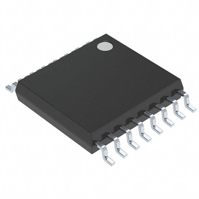
The NCD9830 is available in a 16−lead TSSOP package and
operates over a wide supply range of 2.7 to 5.5 V.
Features
•
•
•
•
•
•
•
•
8−bit ADC
8 Single−ended Inputs/4 Differential Inputs
2.7 V to 5.5 V Operation
Built in 2.5 V Reference
2 Address Selection Pins
Low Power Consumption
I2C Compliant Interface − Standard, Fast and High Speed Modes
These Devices are Pb−Free, Halogen Free/BFR Free and are RoHS
Compliant
© Semiconductor Components Industries, LLC, 2013
November, 2013 − Rev. 3
1
http://onsemi.com
MARKING
DIAGRAM
16
16
1
TSSOP−16
DT SUFFIX
CASE 948F
A
L
Y
W
G
1
NCD
9830
ALYWG
G
= Assembly Location
= Wafer Lot
= Year
= Work Week
= Pb−Free Package
(*Note: Microdot may be in either location)
ORDERING INFORMATION
See detailed ordering and shipping information in the package
dimensions section on page 15 of this data sheet.
Publication Order Number:
NCD9830/D
�NCD9830
CH0
1
16
VDD
CH1
2
15
SDA
CH2
3
14
SCL
CH3
4
13
A1
CH4
5
12
A0
CH5
6
11
COM
CH6
7
10
REFIN/REFOUT
CH7
8
9
GND
Figure 1. Pin Configuration (Top View)
A1
A0
SDA
SCL
13
12
15
14
NCD9830
I2C INTERFACE
CH0
1
CH1
2
CH2
3
CH3
4
CH4
5
CH5
6
CH6
7
CH7
8
COM
1
ANALOG
MUX
8−Bit
A−TO−D
CONVERTER
Temporary
Data Storage
2.5V
Ref
16
9
10
VDD
GND
REFIN/REFOUT
Figure 2. Functional Block Diagram of NCD9830
http://onsemi.com
2
�NCD9830
Table 1. PIN FUNCTION DESCRIPTION
Pin No.
Pin Name
1
CH0
Analog Input.
Description
2
CH1
Analog Input.
3
CH2
Analog Input.
4
CH3
Analog Input.
5
CH4
Analog Input.
6
CH5
Analog Input.
7
CH6
Analog Input.
8
CH7
Analog Input.
9
GND
Power Supply Ground.
10
REFIN /
REFOUT
11
COM
12
A0
Functions as an I2C address selection bit.
13
A1
Functions as an I2C address selection bit.
Internal 2.5 V reference or external reference input.
Common to analog input channel (typically connected to GND).
14
SCL
Serial Clock Input. Open−drain pin; needs a pull−up resistor.
15
SDA
I2C Serial Bi−directional Data Input/Output. Open−drain pin; needs a pull−up resistor.
16
VDD
Positive Supply Voltage. Bypass to ground with a 0.1 mF bypass capacitor.
Table 2. ABSOLUTE MAXIMUM RATINGS
Rating
Symbol
Value
Unit
VDD
−0.3 to +6.5
V
−0.3 to VDD +0.3
V
VDD
V
TJ(max)
150.7
°C
TSTG
−65 to 160
°C
ESD Capability, Human Body Model (Note 1)
ESDHBM
3
kV
ESD Capability, Machine Model (Note 1)
ESDMM
150
V
Supply Voltage (VDD)
Analog input voltage to GND
Voltage on any pin (not analog inputs)
Maximum Junction Temperature
Storage Temperature Range
Stresses exceeding Maximum Ratings may damage the device. Maximum Ratings are stress ratings only. Functional operation above the
Recommended Operating Conditions is not implied. Extended exposure to stresses above the Recommended Operating Conditions may affect
device reliability.
1. Refer to ELECTRICAL CHARACTERISTICS and APPLICATION INFORMATION for Safe Operating Area.
Table 3. OPERATING RANGES
Rating
Operating Supply Voltage
Operating Ambient Temperature Range
Symbol
Min
Max
Unit
VDD
2.7
5.5
V
TA
−40
125
°C
2. Refer to ELECTRICAL CHARACTERISTICS and APPLICATION INFORMATION for Safe Operating Area.
http://onsemi.com
3
�NCD9830
Table 4. ELECTRICAL CHARACTERISTICS +2.7 V
TA = −40°C to +125°C, VDD = 2.7 V, VREF = 2.5 V, SCL Freq = 3.4 MHz, unless otherwise noted.
Parameter
Test Conditions
Min
Typ
Max
Unit
0
VREF
V
ANALOG INPUT
Full scale input range
Positive and negative input
Max input range
Positive input
−0.2
VDD +
0.2
V
Negative input
−0.2
0.2
V
Capacitance
25
pF
Leakage Current
±1
mA
SYSTEM PERFORMANCE
8
No Missing Codes
Bits
Integral Linearity Error
±0.1
±0.5
LSB
Differential Linearity Error
±0.1
±0.5
LSB
Offset Error
+0.5
+1
LSB
Offset Error Match
±0.05
±0.25
LSB
Gain Error
±0.1
±0.5
LSB
Gain Error Match
±0.05
±0.25
LSB
Noise
100
mVRMS
Power Supply Rejection
72
dB
SAMPLING DYNAMICS
Throughput Frequency
High speed mode: SCL = 3.4 MHz
70
kSPS
Fast mode: SCL = 400 kHz
10
kSPS
2.5
kSPS
Standard mode: SCL = 100 kHz
Conversion Time
5
ms
AC ACCURACY
Total Harmonic Distortion
VIN = 2.5 Vpp at 1 kHz
−72
dB
Signal−to−Ratio
VIN = 2.5 Vpp at 1 kHz
50
dB
Signal−to−(Noise+Distortion) Ratio
VIN = 2.5 Vpp at 1 kHz
49
dB
Spurious Free Dynamic Range
VIN = 2.5 Vpp at 1 kHz
68
dB
90
dB
Channel to channel isolation
VOLTAGE REFERENCE OUTPUT
2.475
Range
Internal Reference Drift
Output Impedance
Internal reference ON
Internal reference OFF
Quiescent Current
Internal Reference ON, SCL and SDA
pulled HIGH
2.5
2.525
V
15
ppm/°C
700
W
1
GW
850
mA
VOLTAGE REFERENCE INPUT
0.05
Range
Resistance
Current Drain
High Speed Mode: SCL = 3.4 MHz
DIGITAL INPUT/OUTPUT
http://onsemi.com
4
VDD
V
1
GW
20
mA
�NCD9830
Table 4. ELECTRICAL CHARACTERISTICS +2.7 V
TA = −40°C to +125°C, VDD = 2.7 V, VREF = 2.5 V, SCL Freq = 3.4 MHz, unless otherwise noted.
Parameter
Test Conditions
Min
Typ
Max
Unit
DIGITAL INPUT/OUTPUT
Logic Levels:
Input Leakage:
VIH
0.7 x
VDD
VDD +
0.5
V
VIL
0
0.3 x
VDD
V
VOL
Minimum 3 mA sink current
0.4
V
IIH
VIH = VDD + 0.5
10
mA
IIL
VIL = 0 V
−10
mA
POWER SUPPLY REQUIREMENTS
2.7
VDD
Quiescent Current
Power Dissipation
Power Down Mode (Wrong address selected)
Full Power Down
3.6
V
320
mA
High speed mode: SCL = 3.4 MHz
225
Fast mode: SCL = 400 kHz
100
mA
Standard mode: SCL = 100 kHz
60
mA
High speed mode: SCL = 3.4 MHz
675
Fast mode: SCL = 400 kHz
300
mW
Standard mode: SCL = 100 kHz
180
mW
High speed mode: SCL = 3.4 MHz
70
mA
Fast mode: SCL = 400 kHz
25
mA
Standard mode: SCL = 100 kHz
6
mA
SCL, SDA pulled HIGH
1000
mW
400
3000
nA
Typ
Max
Unit
0
VREF
V
VDD +
0.2
V
Table 5. ELECTRICAL CHARACTERISTICS +5 V
TA = −40°C to +125°C, VDD = 5 V, VREF = 5 V (external), SCL Freq = 3.4 MHz, unless otherwise noted.
Parameter
Test Conditions
Min
ANALOG INPUT
Full scale input range
Positive and negative input
Max input range
Positive input
−0.2
Negative input
−0.2
0.2
V
Capacitance
25
pF
Leakage Current
±1
mA
SYSTEM PERFORMANCE
No Missing Codes
8
Bits
Integral Linearity Error
±0.1
±0.5
LSB
Differential Linearity Error
±0.1
±0.5
LSB
Offset Error
+0.5
+1
LSB
Offset Error Match
±0.05
±0.25
LSB
Gain Error
±0.1
±0.5
LSB
Gain Error Match
±0.05
±0.25
LSB
Noise
100
mVRMS
Power Supply Rejection
72
dB
http://onsemi.com
5
�NCD9830
Table 5. ELECTRICAL CHARACTERISTICS +5 V
TA = −40°C to +125°C, VDD = 5 V, VREF = 5 V (external), SCL Freq = 3.4 MHz, unless otherwise noted.
Parameter
Test Conditions
Min
Typ
Max
Unit
70
kSPS
Fast mode: SCL = 400 kHz
10
kSPS
Standard mode: SCL = 100 kHz
2.5
kSPS
SAMPLING DYNAMICS
Throughput Frequency
High speed mode: SCL = 3.4 MHz
Conversion Time
5
ms
AC ACCURACY
Total Harmonic Distortion
VIN = 2.5 Vpp at 1 kHz
−72
dB
Signal−to−Ratio
VIN = 2.5 Vpp at 1 kHz
50
dB
Signal−to−(Noise+Distortion) Ratio
VIN = 2.5 Vpp at 1 kHz
49
dB
Spurious Free Dynamic Range
VIN = 2.5 Vpp at 1 kHz
68
dB
90
dB
Channel to channel isolation
VOLTAGE REFERENCE OUTPUT
Range
2.475
Internal Reference Drift
Output Impedance
Internal reference ON
Internal reference OFF
Quiescent Current
Internal Reference ON, SCL and SDA
pulled HIGH
2.5
2.525
V
15
ppm/°C
700
W
1
GW
1300
mA
VOLTAGE REFERENCE INPUT
Range
0.05
Resistance
Current Drain
High Speed Mode: SCL = 3.4 MHz
VDD
V
1
GW
20
mA
DIGITAL INPUT/OUTPUT
Logic Levels:
Input Leakage:
VIH
0.7 x
VDD
VDD +
0.5
V
VIL
0
0.3 x
VDD
V
0.4
V
10
mA
VOL
Minimum 3 mA sink current
IIH
VIH = VDD + 0.5
IIL
VIL = 0 V
−10
mA
POWER SUPPLY REQUIREMENTS
VDD
Quiescent Current
Power Dissipation
Power Down Mode (Wrong address selected)
Full Power Down
4.75
5.25
V
1000
mA
High speed mode: SCL = 3.4 MHz
750
Fast mode: SCL = 400 kHz
300
mA
Standard mode: SCL = 100 kHz
150
mA
High speed mode: SCL = 3.4 MHz
3.75
5
mW
Fast mode: SCL = 400 kHz
1.5
mW
Standard mode: SCL = 100 kHz
0.75
mW
High speed mode: SCL = 3.4 MHz
400
mA
Fast mode: SCL = 400 kHz
150
mA
Standard mode: SCL = 100 kHz
35
mA
SCL, SDA pulled HIGH
TA = −40°C to 85°C
TA = −40°C to 125°C
400
400
http://onsemi.com
6
3000
3500
nA
�NCD9830
TIMING CHARACTERISTICS
Table 6. I2C TIMING
Parameter (Note 3)
Symbol
Conditions
Min
Max
Unit
100
400
3.4
1.7
kHz
kHz
MHz
MHz
Clock Frequency
fSCL
Standard Mode
Fast Mode
High speed Mode (100 pF)
High speed Mode (400 pF)
10
Bus Free Time
tBUF
Standard Mode
Fast Mode
4.7
1.3
ms
ms
Standard Mode
Fast Mode
High speed Mode
4.0
600
160
ms
ns
ns
Start Hold Time (Note 4)
tHD;STA
SCL Low Time
tLOW
Standard Mode
Fast Mode
High speed Mode (100 pF)
High speed Mode (400 pF)
4.7
1.3
160
320
ms
ms
ns
ns
SCL High Time
tHIGH
Standard Mode
Fast Mode
High speed Mode (100 pF)
High speed Mode (400 pF)
4.0
600
60
120
ms
ns
ns
ns
tSU;STA
Standard Mode
Fast Mode
High speed Mode
4.7
600
160
ms
ns
ns
Data Setup Time (Note 5)
tSU;DAT
Standard Mode
Fast Mode
High speed Mode
250
100
10
ns
Data Hold Time (Note 6)
tHD;DAT
Standard Mode
Fast Mode
High speed Mode (100 pF)
High speed Mode (400 pF)
0
0
0
0
3.45
0.9
70
150
ms
ms
ns
ns
SCL Rise Time
tRCL
Standard Mode
Fast Mode
High speed Mode (100 pF)
High speed Mode (400 pF)
20+0.1CB
10
20
1000
300
40
80
ns
ns
ns
ns
SCL Rise Time (after repeated start)
tRCL1
Standard Mode
Fast Mode
High speed Mode (100 pF)
High speed Mode (400 pF)
20+0.1CB
10
20
1000
300
80
160
ns
ns
ns
ns
SCL Fall Time
tFCL
Standard Mode
Fast Mode
High speed Mode (100 pF)
High speed Mode (400 pF)
20+0.1CB
10
20
300
300
40
80
ns
ns
ns
ns
SDA Rise Time
tRDA
Standard Mode
Fast Mode
High speed Mode (100 pF)
High speed Mode (400 pF)
20+0.1CB
10
20
1000
300
80
160
ns
ns
ns
ns
SDA Fall Time
tFDA
Standard Mode
Fast Mode
High speed Mode (100 pF)
High speed Mode (400 pF)
20+0.1CB
10
20
300
300
80
160
ns
ns
ns
ns
Start Setup Time
Stop Setup Time
tSU;STO
Capacitive load
CB
3.
4.
5.
6.
Standard Mode
Fast Mode
High speed Mode
0.4
600
160
ms
ns
ns
400
pF
Guaranteed by design, but not production tested.
Time from 10% of SDA to 90% of SCL.
Time for 10%or 90% of SDA to 10% of SCL.
A device must internally provide a hold time of at least 300 ns for the SDA signal to bridge the undefined region of the falling edge of
SCL.
http://onsemi.com
7
�NCD9830
Table 6. I2C TIMING
Parameter (Note 3)
Symbol
Conditions
Min
Glitch Immunity
tSP
Fast Mode
High−speed Mode
Noise margin at high level
VNH
Standard Mode
Fast Mode
High speed Mode
0.2 VDD
Standard Mode
Fast Mode
High speed Mode
0.1 VDD
Noise margin at low level
3.
4.
5.
6.
VNL
Max
Unit
50
10
ns
ns
V
V
Guaranteed by design, but not production tested.
Time from 10% of SDA to 90% of SCL.
Time for 10%or 90% of SDA to 10% of SCL.
A device must internally provide a hold time of at least 300 ns for the SDA signal to bridge the undefined region of the falling edge of
SCL.
Figure 3. Serial Interface Timing
http://onsemi.com
8
�NCD9830
TYPICAL CHARACTERISTICS
0
0.5
−10
0.4
−20
0.3
−30
0.2
−40
0.1
INL (LSB)
AMPLITUDE (dB)
TA = +25°C, VDD = +2.7 V, VREF = External 2.5 V, fSAMPLE = 50 kHz, unless otherwise stated.
−50
−60
−0.2
−80
−0.3
−90
−0.4
5
0
10
15
20
−0.5
25
0.4
0.3
0.3
0.2
0.2
0.1
0.1
0
−0.1
100
125 150 175 200 225 250
0
−0.1
−0.2
−0.2
−0.3
−0.3
−0.4
−0.4
50
75
100
−0.5
125 150 175 200 225 250
0
25
50
75
100
125 150 175 200 225 250
OUTPUT CODE
OUTPUT CODE
Figure 6. DNL vs. Code (EXT REF)
Figure 7. INL vs. Code (INT REF)
0.5
0.2
0.4
0.15
DELTA FROM 25°C (LSB)
0.3
0.2
0.1
0
−0.1
0.1
0.05
0
−0.05
−0.2
−0.3
−0.1
−0.15
−0.4
−0.5
75
OUTPUT CODE
0.4
25
50
Figure 5. INL vs. Code (EXT REF)
0.5
0
25
FREQUENCY (kHz)
0.5
−0.5
0
Figure 4. FFT vs. Frequency
INL (LSB)
DNL (LSB)
−0.1
−70
−100
DNL (LSB)
0
0
25
50
75
100
−0.2
−50
125 150 175 200 225 250
−30 −10
10
30
50
70
90
110
OUTPUT CODE
TEMPERATURE (°C)
Figure 8. DNL vs. Code (INT REF)
Figure 9. Change in Offset vs. Temperature
http://onsemi.com
9
130
�NCD9830
TYPICAL CHARACTERISTICS
TA = +25°C, VDD = +2.7 V, VREF = External 2.5 V, fSAMPLE = 50 kHz, unless otherwise stated.
0.2
2.55
2.5375
INTERNAL REFERENCE (V)
DELTA FROM 25°C (LSB)
0.15
0.1
0.05
0
−0.05
−0.1
−0.15
2.525
2.5125
2.5
2.4875
2.475
2.4625
2.45
2.4375
2.425
−0.2
−50
−30 −10
10
30
50
70
90
110
2.4125
−45
130
−25
−5
15
35
55
75
TEMPERATURE (°C)
TEMPERATURE (°C)
Figure 10. Change in Gain vs. Temperature
Figure 11. Internal VREF vs. Temperature
1000
95
400
800
SUPPLY CURRENT (mA)
SUPPLY CURRENT (nA)
900
700
600
500
400
300
200
100
−30 −10
10
30
50
70
90
110
300
250
200
150
100
−50
130
−30 −10
10
30
50
70
90
110
130
TEMPERATURE (°C)
TEMPERATURE (°C)
Figure 12. Power−Down Supply Current vs.
Temperature
Figure 13. Supply Current vs. Temperature
300
3
250
2.5
INTERNAL VREF (V)
SUPPLY CURRENT (mA)
0
−50
350
200
150
100
50
No Cap
2
1 mF
1.5
1
0.5
0
0
10
100
1000
10000
−0.5
0
500
1000
1500
2000
2500
I2C BUS RATE (kHz)
TURN−ON−TIME (ms)
Figure 14. Supply Current vs. I2C Bus Rate
Figure 15. Internal VREF vs. Turn−ON Time
http://onsemi.com
10
3000
�NCD9830
CIRCUIT INFORMATION
OPERATION
The NCD9830 is a low power successive approximation
ADC with a built in 8 channel multiplexer and 8 bit
resolution. The 8 bit resolution assures high noise immunity
and fast digitization that makes this device suitable for
medium to high speed applications. The device internal
circuitry operates at speed higher than the conversion time
of the device because of the binary algorithm used. The
algorithm is based on approximating the input signal by
comparing with successive analog signal generated from the
built in DAC.
The device can be operated at supply voltages of 2.7 V and
5 V. The liberty of supply voltage variation must be used
with appropriate reference voltage selection. The NCD9830
internal DAC can be configured with an externally (50 mV
−5 V) supplied or an internally internally generated
reference voltage of 2.5 V. However, to avail full dynamic
range an external reference of 5 V must be used while
operating the device at 5 V supply voltage. The internal 2.5
V reference voltage is sufficient for full dynamic range
while operating the device at 2.7 V.
The value of each output bit is evaluated on the basis of
output of the comparator. The converter requires
N conversion periods to give N bit digital output of the input
analog signal. The SAR register stores the digital equivalent
bits of the input analog signal and can be read by the master
device using an I2C interface. The main building block of the
device are
i.
Digital to Analog Converter
ii.
Comparator
iii.
Digital Logic
128C
4C
8C
2C
C
Vin
Figure 16. The Acquisition Phase of a Typical ADC
Conversion Phase: The conversion phase is administered
by a two phase non overlapping clock with phases f1 and f2
respectively.
During f1 the bottom plates of all the capacitors are
grounded i.e the top plates of all the capacitors are now Vin
times higher than the ground. As the conversion process
starts the digital control sets all the bits zero except the MSB
in the SAR register. During the f2 the capacitors associated
with MSB is connected to VREF while others are connected
to ground. In this way the DAC generates analog voltage of
magnitude VREF/2. The analog output of DAC is compared
with the input analog signal. The digital control logic sets the
MSB to 1 if comparator output is high and 0 otherwise. Thus
the first step of SAR algorithm decides whether the input
signal is greater or less than VREF/2. The approximation
process is then run again with the MSB in its proven value
and the next lower bit is set to 1. This gives a general
direction path and the remaining approximations will
converge the output in this direction.
Vin
Digital to Analog Converter
A charge scaling DAC is used due to its compatibility with
the switch capacitor circuits. The DAC operation consists of
two phases called acquisition phase and the conversion
phase. The acquisition phase is analogous to sample and
hold circuit while the conversion phase is the process of
conversion of the internal digital word in to an analog
output.
Acquisition phase: The top plates of all the capacitors on
the array are connected to the ground and the bottom plates
are connected to the applied voltage Vin. Thus there is
a charge proportional to input voltage on the capacitor array.
After acquisition the top and bottom plates are disconnected
from their respective connections.
128C
f2
f1
4C
8C
f2
f1
f2
f1 f2
2C
C
f1
VREF
Figure 17. The Conversion Phase of a Typical ADC
Comparator
A switch capacitor comparator is used to alleviate the
effects of input offset voltage. The issue of charge injection
is controlled by using fully differential topology.
http://onsemi.com
11
�NCD9830
Digital Logic
serial clock line, SCL, remains high. This indicates
that an address/data stream will follow. All slave
peripherals connected to the serial bus respond to
the START condition, and shift in the next eight
bits, consisting of a 7−bit address (MSB first) plus
an R/W bit, which determines the direction of the
data transfer, i.e., whether data will be written to
or read from the slave device. The peripheral
whose address corresponds to the transmitted
address responds by pulling the data line low
during the low period before the ninth clock pulse,
known as the Acknowledge Bit. All other devices
on the bus now remain idle while the selected
device waits for data to be read from or written to
it. If the R/W bit is a 0, the master will write to the
slave device. If the R/W bit is a 1, the master will
read from the slave device.
2. Data is sent over the serial bus in sequences of
nine clock pulses, eight bits of data followed by an
Acknowledge Bit from the slave device.
Transitions on the data line must occur during the
low period of the clock signal and remain stable
during the high period, as a low−to−high transition
when the clock is high may be interpreted as a
STOP signal. The number of data bytes that can be
transmitted over the serial bus in a single READ or
WRITE operation is limited only by what the
master and slave devices can handle.
3. When all data bytes have been read or written,
stop conditions are established. In WRITE mode,
the master will pull the data line high during the
10th clock pulse to assert a STOP condition. In
READ mode, the master device will override the
acknowledge bit by pulling the data line high
during the low period before the ninth clock pulse.
This is known as No Acknowledge. The master
will then take the data line low during the low
period before the tenth clock pulse, then high
during the tenth clock pulse to assert a STOP
condition.
The function of the digital logic is to generate the binary
word to be compared with the input analog signal in each
approximation cycle. The result of each approximation
cycle is stored in the SAR register. In short the digital logic
determines the value of each output bit in a sequential
manner base don the output of the comparator.
ANALOG CHANNELS
The analog inputs (CH0−CH7) are multiplexed into the
on−chip successive approximation, analog−digital
converter. This has a resolution of 8 bits. The basic input
range is 0 V to VDD. When not performing a conversion or
being addressed, the ADC core is powered off to preserve
power. The internal clock is also powered off.
REFERENCE
The NCD9830 can operate with either its own internal
2.5 V reference or an externally supplied reference. If using
a 5 V supply then an external 5 V reference needs to be used
in order to provide the full range for the 0 to VDD analog
input channels. The internal 2.5 V reference will still be
sufficient to provide full dynamic range for the 0 to VDD
analog input channels.
SERIAL BUS INTERFACE
Control of the NCD9830 is carried out via the I2C bus. The
NCD9830 is connected to this bus as a slave device, under
the control of a master device. The NCD9830 has a 7−bit
serial bus address. The upper 5 bits of the device address are
10010. The lower 2 bits are set by pins 12 and 13. Table 7
shows the 7−bit address for each of the pin states. The
address pins can be connected to VDD or GND and the
address is set by the state of these pins on power up.
The logic of this address pin is monitored on power up on
the first I2C transaction, more precisely, on the low−to−high
transition at the beginning of the eighth SCL pulse.
The ability to make hardwired changes to the I2C slave
address allows the user to avoid conflicts with other devices
sharing the same I2C address, for example, if more than one
NCD9830 is used in a system. NCD9830 is compatible to all
three operating modes of I2C interface i.e Standard
(100 kHz), Fast (400 kHz) and high speed (3.4 MHz) modes.
COMMAND BYTE
NCD9830 can be operated in different modes depending
on the internal power state of different circuit sections and
input configuration (single ended or differential). Command
byte also contains three channel select Cx bits of the internal
eight channel multiplexer. The format of the command byte
is as follows
The 8 bit command code is used to configure:
• Either a single ended or differential measurement
• Channel to be selected
• Power down/reference options
Table 7. I2C ADDRESS OPTIONS
A1
A0
Address
0
0
0x48
0
1
0x49
1
0
0x4A
1
1
0x4B
The serial bus protocol operates as follows:
1. The master initiates data transfer by establishing a
START condition, defined as a high−to−low
transition on the serial data line SDA while the
http://onsemi.com
12
�NCD9830
MSB
6
5
4
3
2
1
0
SD
C2
C1
C0
PD1
PD0
x
x
is to be used or the external one. See Power Down Selection
Table 8 for more detail.
Bit 7: SD − this configures the type of input to be used. If set
to 0 then the device performs a differential measurement. If
set to 1 then a single ended measurement is made.
Bit 6−4: C2−C0 − these are the channel selection bits. See
Channel Selector table below for more detail.
Bit 3−2: PD1−PD0 − these bits let the use select whether the
ADC is powered on, off and whether the internal reference
Table 8. POWER DOWN SELECTION
PD1
PD0
Description
0
0
Power down between ADC conversions
0
1
Internal reference OFF, ADC ON
1
0
Internal reference ON, ADC OFF
1
1
Internal reference ON. ADC ON
Table 9. CHANNEL SELECTOR
CHANNEL SELECTION CONTROL
SD
C2
C1
C0
CH0
CH1
CH2
CH3
CH4
CH5
CH6
CH7
COM
0
0
0
0
+IN
−IN
−
−
−
−
−
−
−
0
0
0
1
−
−
+IN
−IN
−
−
−
−
−
0
0
1
0
−
−
−
−
+IN
−IN
−
−
−
0
0
1
1
−
−
−
−
−
−
+IN
−IN
−
0
1
0
0
−IN
+IN
−
−
−
−
−
−
−
0
1
0
1
−
−
−IN
+IN
−
−
−
−
−
0
1
1
0
−
−
−
−
−IN
+IN
−
−
−
0
1
1
1
−
−
−
−
−
−
−IN
+IN
−
1
0
0
0
+IN
−
−
−
−
−
−
−
−IN
1
0
0
1
−
−
+IN
−
−
−
−
−
−IN
1
0
1
0
−
−
−
−
+IN
−
−
−
−IN
1
0
1
1
−
1
1
0
0
1
1
0
1
1
1
1
1
1
1
−
−
−
−
−
+IN
−
−IN
+IN
−
−
−
−
−
−
−IN
−
−
−
+IN
−
−
−
−
−IN
0
−
−
−
−
−
+IN
−
−
−IN
1
−
−
−
−
−
−
−
+IN
−IN
http://onsemi.com
13
�NCD9830
INITIATING CONVERSIONS
Communication in Standard/Fast Mode
device initiates the conversion cycle by turning on the
converter circuit after it receives the channel selection bits
(SD, C2-C0) of the Command byte. After receiving the
Command byte the NCD 9830 sends an acknowledge bit.
The device is now ready to be read by the master.
Communication in standard/fast mode corresponds to
a clock speed of 100/400 kHz. The device address is sent
over the bus followed by R/W set to 0. This is followed by
the Command byte. If the Command byte is correct the
1
9
1
9
SCLK
SDATA
1
0
0
1
0
A1
A0
R/W
SD
C2
C1
C0
PD1
PD0
X
X
ACK. BY
NCD9830
START BY
MASTER
ACK. BY
NCD9830
FRAME 2
COMMAND BYTE
FRAME 1
SERIAL BUS ADDRESS BYTE
Figure 18. Write Addressing the Device to Write the Command Byte
1
9
1
9
SCLK
SDATA
1
0
0
START/RESTART
BY
MASTER
1
0
A1
A0
R/W
D7
D6
D5
ACK. BY
NCD9830
FRAME 1
SERIAL BUS ADDRESS BYTE
D4
D3
D2
D1
D0
NOT ACK. BY
MASTER
FRAME 2
FIRST DATA BYTE
STOP
Figure 19. Conversation between Master and NCD9830 in Standard/Fast Mode
1
9
HIGH SPEED CLOCK HOLDING LOW
DURING CONVERSION
SCLK
SDATA
1
0
0
1
0
A1
A0
R/W
0
ACK. BY
NCD9830
START/RESTART
BY
MASTER
SERIAL BUS ADDRESS BYTE
CONVERSION TIME
CLOCK CONTNUES AFTER
CONVERSION
SDATA
D0
D1
D2
D3
D4
D5
D6
D7
N.ACK. BY STOP. BY
MASTER
MASTER
Figure 20. Conversation Between Master and NCD9830 in High Speed Mode
During read operation the device address is sent over the
bus followed by R/W set to 1 followed by the acknowledge
bit from the slave .Data can be read from the device in the
form of a 8 bit byte. The MSB of the data word is D7 and
LSB is D0.
START
0
0
0
0
1
X
X
X
N.ACK
The START condition bit is initiated by master and
N.ACK is initiated by NCD9830. The master code must be
run in fast mode to enter in the high speed mode.
High speed operation does not give enough time span for
a conversion to be completed between the start condition
initiated by the master and the read cycle. Therefore, in high
speed mode NCD9830 stretches the clock at low level after
the read cycle is initiated by the master until the conversion
is complete. Master can decide to remain in high speed mode
Communication in High Speed Mode
Communication in high speed mode corresponds to
a clock speed of 3.4 MHz. Master initiates a high speed
master code that change the mode from standard/fast to high
speed. The high speed master code format is as follows:
http://onsemi.com
14
�NCD9830
When the device turns on for the first time the internal
reference is OFF. Proper settling time must be allowed while
switching any reference (external or internal) ON or OFF
before any conversion is initiated. Depending on the I2C
operation mode (standard, fast or high speed) the settling
time would vary.
by initiating a RESTART condition instead of STOP at the
end of read sequence. A STOP bit at the end of read cycle
changes the mode back to the standard/fast. A typical high
speed read operation is shown in Figure 20.
Reference Voltage Selection
The internal reference can be turned ON or OFF
depending on the Command byte bit PD1 status.
LAYOUT CONSIDERATIONS
• Extra care must be taken while using external reference
Digital boards are electrically noisy environments, and
the NCD9830 SAR architecture is sensitive to power supply
transients, reference voltage variation and other noise
sources in the circuit. Any sudden transient spike can affect
the accuracy of over all conversion result. So care must be
taken to minimize noise induced at the device inputs. Take
the following precautions:
• Place a 0.1 mF bypass capacitor close to the VDD pin. In
extremely noisy environments, where the impedance
between the VDD and the power supply is high a bigger
capacitor with capacitance value from 1−10 mF must be
used.
voltage for the device. Using a 5 V external reference
voltage may require to connect the I/O REF pin directly
to VDD. Any transient glitches and spikes will induce
a lot of noise in the reference voltage that would
compromise the overall performance of the ADC.
Appropriate measures must be taken to avoid pollution
of reference voltage. Place the component far from the
microprocessor or any other digital circuitry to avoid
high frequency noise injection in the analog portions of
ADC. A clean analog ground must be used with
a dedicated analog ground plane
ORDERING INFORMATION
Device
NCD9830DBR2G
Package
Shipping†
TSSOP−16
(Pb−Free)
2500 / Tape & Reel
†For information on tape and reel specifications, including part orientation and tape sizes, please refer to our Tape and Reel Packaging
Specifications Brochure, BRD8011/D.
http://onsemi.com
15
�MECHANICAL CASE OUTLINE
PACKAGE DIMENSIONS
TSSOP−16
CASE 948F−01
ISSUE B
16
DATE 19 OCT 2006
1
SCALE 2:1
16X K REF
0.10 (0.004)
0.15 (0.006) T U
M
T U
S
V
S
K
S
ÉÉÉ
ÇÇÇ
ÇÇÇ
ÉÉÉ
K1
2X
L/2
16
9
J1
B
−U−
L
SECTION N−N
J
PIN 1
IDENT.
N
8
1
0.25 (0.010)
M
0.15 (0.006) T U
S
A
−V−
NOTES:
1. DIMENSIONING AND TOLERANCING PER
ANSI Y14.5M, 1982.
2. CONTROLLING DIMENSION: MILLIMETER.
3. DIMENSION A DOES NOT INCLUDE MOLD
FLASH. PROTRUSIONS OR GATE BURRS.
MOLD FLASH OR GATE BURRS SHALL NOT
EXCEED 0.15 (0.006) PER SIDE.
4. DIMENSION B DOES NOT INCLUDE
INTERLEAD FLASH OR PROTRUSION.
INTERLEAD FLASH OR PROTRUSION SHALL
NOT EXCEED 0.25 (0.010) PER SIDE.
5. DIMENSION K DOES NOT INCLUDE DAMBAR
PROTRUSION. ALLOWABLE DAMBAR
PROTRUSION SHALL BE 0.08 (0.003) TOTAL
IN EXCESS OF THE K DIMENSION AT
MAXIMUM MATERIAL CONDITION.
6. TERMINAL NUMBERS ARE SHOWN FOR
REFERENCE ONLY.
7. DIMENSION A AND B ARE TO BE
DETERMINED AT DATUM PLANE −W−.
N
F
DETAIL E
−W−
C
0.10 (0.004)
−T− SEATING
PLANE
D
H
G
DETAIL E
DIM
A
B
C
D
F
G
H
J
J1
K
K1
L
M
MILLIMETERS
MIN
MAX
4.90
5.10
4.30
4.50
−−−
1.20
0.05
0.15
0.50
0.75
0.65 BSC
0.18
0.28
0.09
0.20
0.09
0.16
0.19
0.30
0.19
0.25
6.40 BSC
0_
8_
INCHES
MIN
MAX
0.193 0.200
0.169 0.177
−−− 0.047
0.002 0.006
0.020 0.030
0.026 BSC
0.007
0.011
0.004 0.008
0.004 0.006
0.007 0.012
0.007 0.010
0.252 BSC
0_
8_
GENERIC
MARKING DIAGRAM*
SOLDERING FOOTPRINT
7.06
16
XXXX
XXXX
ALYW
1
1
0.65
PITCH
16X
0.36
DOCUMENT NUMBER:
DESCRIPTION:
16X
1.26
98ASH70247A
TSSOP−16
DIMENSIONS: MILLIMETERS
XXXX
A
L
Y
W
G or G
= Specific Device Code
= Assembly Location
= Wafer Lot
= Year
= Work Week
= Pb−Free Package
*This information is generic. Please refer to
device data sheet for actual part marking.
Pb−Free indicator, “G” or microdot “ G”,
may or may not be present.
Electronic versions are uncontrolled except when accessed directly from the Document Repository.
Printed versions are uncontrolled except when stamped “CONTROLLED COPY” in red.
PAGE 1 OF 1
ON Semiconductor and
are trademarks of Semiconductor Components Industries, LLC dba ON Semiconductor or its subsidiaries in the United States and/or other countries.
ON Semiconductor reserves the right to make changes without further notice to any products herein. ON Semiconductor makes no warranty, representation or guarantee regarding
the suitability of its products for any particular purpose, nor does ON Semiconductor assume any liability arising out of the application or use of any product or circuit, and specifically
disclaims any and all liability, including without limitation special, consequential or incidental damages. ON Semiconductor does not convey any license under its patent rights nor the
rights of others.
© Semiconductor Components Industries, LLC, 2019
www.onsemi.com
�onsemi,
, and other names, marks, and brands are registered and/or common law trademarks of Semiconductor Components Industries, LLC dba “onsemi” or its affiliates
and/or subsidiaries in the United States and/or other countries. onsemi owns the rights to a number of patents, trademarks, copyrights, trade secrets, and other intellectual property.
A listing of onsemi’s product/patent coverage may be accessed at www.onsemi.com/site/pdf/Patent−Marking.pdf. onsemi reserves the right to make changes at any time to any
products or information herein, without notice. The information herein is provided “as−is” and onsemi makes no warranty, representation or guarantee regarding the accuracy of the
information, product features, availability, functionality, or suitability of its products for any particular purpose, nor does onsemi assume any liability arising out of the application or use
of any product or circuit, and specifically disclaims any and all liability, including without limitation special, consequential or incidental damages. Buyer is responsible for its products
and applications using onsemi products, including compliance with all laws, regulations and safety requirements or standards, regardless of any support or applications information
provided by onsemi. “Typical” parameters which may be provided in onsemi data sheets and/or specifications can and do vary in different applications and actual performance may
vary over time. All operating parameters, including “Typicals” must be validated for each customer application by customer’s technical experts. onsemi does not convey any license
under any of its intellectual property rights nor the rights of others. onsemi products are not designed, intended, or authorized for use as a critical component in life support systems
or any FDA Class 3 medical devices or medical devices with a same or similar classification in a foreign jurisdiction or any devices intended for implantation in the human body. Should
Buyer purchase or use onsemi products for any such unintended or unauthorized application, Buyer shall indemnify and hold onsemi and its officers, employees, subsidiaries, affiliates,
and distributors harmless against all claims, costs, damages, and expenses, and reasonable attorney fees arising out of, directly or indirectly, any claim of personal injury or death
associated with such unintended or unauthorized use, even if such claim alleges that onsemi was negligent regarding the design or manufacture of the part. onsemi is an Equal
Opportunity/Affirmative Action Employer. This literature is subject to all applicable copyright laws and is not for resale in any manner.
PUBLICATION ORDERING INFORMATION
LITERATURE FULFILLMENT:
Email Requests to: orderlit@onsemi.com
onsemi Website: www.onsemi.com
◊
TECHNICAL SUPPORT
North American Technical Support:
Voice Mail: 1 800−282−9855 Toll Free USA/Canada
Phone: 011 421 33 790 2910
Europe, Middle East and Africa Technical Support:
Phone: 00421 33 790 2910
For additional information, please contact your local Sales Representative
�