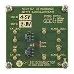
Test Procedure for the NCP152MXTCGEVB Evaluation Board
There is a collection test procedures for NCP152 demoboards. This paper offers some helpful test configuration for first
contact with ONSEMI NCP152 LDO.
1. QUIESCENT CURRENT
Vout_nom+1V or 2.5V
DC
Supply
-
+
μA
Figure 1: Test configuration for measurement IQ, Quiescent Current
1. Connect circuit as shown figure on 1
2. Apply voltage at VInput. Default test Vinput is Vout_nom+1 V or 2.5 V whichever is greater
3. Value shown μA meter is measured quiescent current.
4. Measurement is finished. Disconnect supply voltage.
*Note – Be carefully if any device is connected on output, because leakage current can affect
measurement accuracy.
10/3/2014
1
www.onsemi.com
�2. LOAD REGULATION
Vout_nom+1V or 2.5V
DC
Supply
-
Electronic
load
+
+
IOUT
150 mA
1 mA
V
A
Figure 2: Test configuration for measurement REGLOAD, Load Regulation
1.
2.
3.
4.
5.
6.
7.
8.
10/3/2014
Connect circuit as shown figure on 2
Apply voltage at VInput. Default test Vinput is Vout_nom+1 V or 2.5 V whichever is greater
Set minimal required current I1, e.g. 1 mA, and switch load ON.
Note the value V1 from voltmeter Vo.
Switch load OFF and set maximal required current I2, e.g. 150 mA and switch load ON.
Note the value V2 from voltmeter Vo.
Load regulation is obtained via following formula: REGLOAD=(V1-V2), [V]
Measurement is finished. Disconnect supply voltage.
2
www.onsemi.com
�3. LINE REGULATION
VOUT_NOM+1.5V
VOUT_NOM+0.5V
DC
Supply
-
Electronic
load
+
-
+
IOUT=10mA
V
O
Figure 3: Test configuration for measurement REG LINE, Line Regulation
1.
2.
3.
4.
5.
6.
7.
8.
10/3/2014
Connect circuit as shown on figure 3
Set load to the required current e.g. 10 mA
Set minimal input voltage VI1, VOUT_NOM+1V or 2.5V whichever is greater
Note the value VI1 and VO1.
Set maximal input voltage VI2 = 5.5 V
Note the value VI2 and VO2.
Load regulation is obtained via following formula: REGLINE=(VO1-VO2)/(VI1-VI2), [V/V]
Measurement is finished. Disconnect supply voltage.
3
www.onsemi.com
�4. ENABLE START-UP
OSCILOSCOPE
GENERATOR
~
Electronic
load
+
-
Vout_nom+1V or 2.5V
DC
Supply
IOUT=10mA
+
-
Figure 4: Test configuration for measurement enables response
1.
2.
3.
4.
5.
6.
7.
10/3/2014
Connect circuit as shown on figure 4
Set generator to SQUARE PULSE, 0.9 ≤ AMPLITUDE ≤ VIN, FREQUENCY=10Hz, DUTY=10%
Apply voltage at VInput. Default test Vinput is Vout_nom+1 V or 2.5 V whichever is greater
Set required IOUT, e.g. 10 mA
Connect oscilloscope to EN signal and VOUTPUT.
Watch enable response of the regulator after asserting EN pin.
Measurement is finished. Disconnect supply voltage.
4
www.onsemi.com
�
很抱歉,暂时无法提供与“NCP152MXTCGEVB”相匹配的价格&库存,您可以联系我们找货
免费人工找货