NCP2860 300 mA Very Low Noise, Low Dropout Linear Regulator
The NCP2860 is a low noise, low dropout linear regulator that is offered with an output voltage of 2.77 V. It supplies 300 mA from 3.0 V to 6.0 V input. If wished, the “SET’’ pin enables to adjust the output voltage level that then depends on the voltage applied to this pin. The excellent performances that the NCP2860 features in terms of transient responses, PSRR and noise, make it an ideal solution for audio applications (e.g., audio amplifier drivers).
Features http://onsemi.com
• • • • • • • • • •
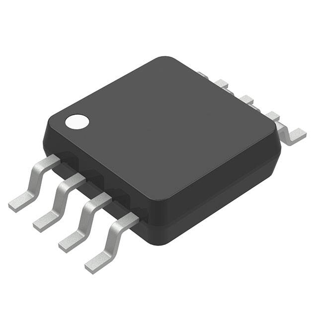
1 Micro8t DM SUFFIX CASE 846A
High Output Current (300 mA Max) Low Output Voltage Noise: 60 mVrms Low Dropout (150 mV @ Iout = 300 mA) Thermal Overload and Short Circuit Protections Very Low Consumption in Shutdown Mode (10 nA) High Power Supply Rejection Ratio (60 dB @ 1.0 kHz) FAULT Indicator Programmable Output Voltage Soft−Start Pb−Free Package is Available
MARKING DIAGRAM
Typical Applications
• Cellular Phone • Handheld Instruments
IN FAULT
LCZ AYW G G 1
Fault Detect Error Amplifier Bandgap − + Drive and Current Limiting OUTPUT BUFFER Feedback Selection Rint1 OUT
LCZ = Specific Device Code A = Assembly Location Y = Year W = Work Week G = Pb−Free Package (Note: Microdot may be in either location)
PIN CONNECTIONS
OUT IN GND OUT 1 2 3 4 (Top View) 8 7 6 5 FAULT STDWN N.C. SET
STDWN
SHUTDOWN
Thermal Sensor
ORDERING INFORMATION
Rint2 Device NCP2860DM277R2 NCP2860DM277R2G Package Micro8 Shipping † 4000/Tape & Reel
Micro8 4000/Tape & Reel (Pb−Free)
GND
SET
†For information on tape and reel specifications, including part orientation and tape sizes, please refer to our Tape and Reel Packaging Specifications Brochure, BRD8011/D. Publication Order Number: NCP2860/D
© Semiconductor Components Industries, LLC, 2006
1
April, 2006 − Rev. 8
�NCP2860
PIN DESCRIPTION
Pin 1, 4 2 3 5 6 7 8 Name OUT IN GND SET N.C. STDWN FAULT Description “OUT’’ is the regulator output. A low ESR, bypass capacitor should be connected for stable operation. “IN’’ is the supply input that is connected to the power source (up to 6.0 V). Bypass with a 2.2 mF capacitor. Ground Ground the “SET’’ pin to set the output voltage to 2.77 V. Refer to the “output voltage setting’’ paragraph if you need to program another value. This pin is non−connected. If the “STDWN’’ pin is low, the circuit enters the shutdown mode. The “FAULT’’ terminal is a high impedance, open drain output. If the circuit is out of regulation, the voltage pin goes low. Otherwise (normal operation or shutdown mode), this pin is high impedance. Connect the pin to ground, if unused.
MAXIMUM RATINGS
Rating Input Voltage, Shutdown Pin, Voltage Range (Note 1) Thermal Resistance (Note 2) Maximum Junction Temperature Storage Temperature Range Lead Temperature (Soldering, 10s) ESD Capability Human Body Model Machine Model Latchup Capability @ 85°C Symbol Vinmax − TJmax TSmax TLmax − − − Value −0.3, +6.0 230 150 − 65 to +150 300 2.0 200 +/−100 Unit V °C/W °C °C °C kV V mA
Stresses exceeding Maximum Ratings may damage the device. Maximum Ratings are stress ratings only. Functional operation above the Recommended Operating Conditions is not implied. Extended exposure to stresses above the Recommended Operating Conditions may affect device reliability. 1. The recommended input voltage range for NCP2860 proper operation is 2.7 V to 6.0 V. 2. Circuit being mounted on a board that has no metal oxide traces attached to the leads. The addition of plated copper can lower the thermal resistance.
http://onsemi.com
2
�NCP2860
TYPICAL ELECTRICAL CHARACTERISTICS (Note 3) (Vin = 3.6 V, SET = GND, TA from −25°C to +85°C, unless otherwise noted.)
Characteristic (2.7 V Option) Output Voltage @ Iout = 100 mA, 300 mA, Vin = 3.2 V and TA = 25°C TA from −25°C to +85°C Supply Current @ Iout = 0, Vin = 3.2 V Supply Current @ Iout = 300 mA, Vin = 3.2 V Supply Current in Shutdown Mode (STDWN Pin Grounded) @ TA = 25°C Dropout Voltage @ Iout = 1.0 mA (Note 4) Dropout Voltage @ Iout = 150 mA (Note 4) Dropout Voltage @ Iout = 300 mA (Note 4) SET Threshold (SET = OUT) @ Iout = 1.0 mA and Vin = 3.6 V or 6.0 V, TA = 25°C TA from −25°C to +85°C SET Input Leakage Current @ VSET = 1.25 V and TA = 25°C Short Circuit Output Current Limitation @ Vin = 3.2 V and Vout = 2.2 V Start−Up Current Limitation @ TA = 25°C, Vin = 3.2 V and Vout = 2.2 V Line Regulation, Vin varying between 3.0 V and 6.0 V @ Iout = 1.0 mA Line Regulation, Vin varying between 3.0 V and 6.0 V @ Iout = 10 mA Line Regulation, Vin varying between 3.0 V and 6.0 V @ Iout = 1.0 mA and (SET = OUT) Line Regulation, Vin varying between 3.0 V and 6.0 V @ Iout = 10 mA and (SET = OUT) Load Regulation, Iout varying from 0.1 mA to 300 mA, SET = OUT, @ Vin = 3.2 V Load Regulation, Iout varying from 0.1 mA to 300 mA, SET Grounded, @ Vin = 3.2 V Output Voltage Noise @ SET = OUT, Cout = 22 mF (Note 5) 10 Hz t f t 10 kHz 10 Hz t f t 100 kHz Output Voltage Noise @ SET = GND, Cout = 22 mF (Note 5) 10 Hz t f t 10 kHz 10 Hz t f t 100 kHz Output Voltage Noise Density @ SET = GND, Cout = 22 mF, 10 Hz t f t 100 kHz (Note 5) Power Supply Rejection Ratio @ 1.0 kHz and Iout = 100 mA Shutdown Threshold (with hysteresis) @ Vin = 5.0 V Shutdown Pin Bias Current @ STDWN = IN or GND and TA = 25°C FAULT Detection Voltage @ Iout = 200 mA FAULT Output Low Voltage @ Isink = 2.0 mA FAULT Output OFF Leakage Current @ TA = 25°C Start−Up Time @ Cout = 10 mF, Vout = 2.7, Iout = 100 mA (Note 5) Thermal Shutdown Threshold Thermal Shutdown Hysteresis Symbol Vout Icc−0 Icc−300 Istdwn Vdrop−1 Vdrop−150 Vdrop−300 Vref Ileak Imax_cc Imax_stup LineReg1 LineReg2 LineReg3 LineReg4 LoadReg1 LoadReg2 − − − − − − − PSRR Vstdwn lstdwn Vfault−th Vfault−out Ifault Tstup Tlimit Htemp − − 0.63 − − − − − − − 35 60 400 60 − − 120 0.15 0.1 60 170 30 − − − − 2.65 100 280 0.4 100 − − − 15 35 − − Min 2.73 2.70 − − − − − − 1.226 1.220 − 310 − −0.1 −0.1 −0.1 −0.1 − − Typ 2.77 2.77 355 1.1 0.01 0.6 75 150 1.244 1.244 10 465 220 0.01 0.01 0.03 0.03 0.0002 0.001 Max 2.81 2.84 700 − 1.0 − 150 250 1.262 1.270 200 700 − 0.1 0.1 0.1 0.1 − − Unit V mA mA mA mV mV mV V nA mA mA %/V %/V %/V %/V %/mA %/mA mVrms
mVrms
nV(Hz)−1/2 dB V nA mV V nA ms °C °C
3. The specification gives the targeted values. This specification may have to be slightly adjusted after the temperature characterization of the die. 4. The dropout voltage is defined as (Vin−Vout) when Vout is 100 mV below the value of Vout when Vin = 3.1 V. 5. Refer to characterization curves for more details.
http://onsemi.com
3
�NCP2860
TYPICAL ELECTRICAL CHARACTERISTICS
(Vin = Vout + 0.5 V, Cin = Cout = 2.2 mF, SET = GND, TA = 25°C, unless otherwise noted.)
0.80 Vout Normalized at Iout = 0 OUTPUT VOLTAGE (%) OUTPUT VOLTAGE (%) 0.40 0.4 0.2 0.0 −0.2 −0.4 −0.6 −0.8 −1.0 −0.80 0 60 120 180 240 300 LOAD CURRENT (mA) −1.2 Vout Normalized at 30°C, Iout = 0 −40 −17 7 30 53 77 100 Iout = 200 mA Iout = 0 mA Iout = 100 mA
0.00
−0.40
TEMPERATURE (°C)
Figure 1. Normalized Output Voltage vs. Load Current
1200 1000 800 TA = 85°C 600 400 200 Vout = 2.77 V 0 0 40 80 120 160 200 240 280 LOAD CURRENT (mA) 0 0.00 TA = 25°C TA = −40°C 600 500
Figure 2. Normalized Output Voltage vs. Temperature
SUPPLY CURRENT (mA)
SUPPLY CURRENT (mA)
TA = 25°C 400 300 TA = −40°C 200 100 Vout = 2.77 V 0.90 1.75 2.60 3.45 4.30 5.15 6.00 TA = +85°C
INPUT VOLTAGE (V)
Figure 3. Supply Current vs. Load Current
180 160 DROPOUT VOLTAGE (mV) 140 120 100 80 60 40 20 0 0 50 100 150 200 250 300 LOAD CURRENT (mA) TA = −40°C TA = 85°C FAULT DETECT THRESHOLD (mV) Vout = 2.77 V TA = 25°C 250
Figure 4. No Load Supply Current vs. Input Voltage
Vout = 2.77 V 200
150
FAULT = HIGH
100
50
FAULT = LOW
0 0 50 100 150 200 250 300 LOAD CURRENT (mA)
Figure 5. Dropout Voltage vs. Load Current
Figure 6. Fault Detect Threshold vs. Load Current
http://onsemi.com
4
�NCP2860
TYPICAL ELECTRICAL CHARACTERISTICS
(Vin = Vout + 0.5 V, Cin = Cout = 2.2 mF, SET = GND, TA = 25°C, unless otherwise noted.)
0 −10 −20 −30 PSSR (dB) −40 −50 −60 −70 −80 −90 0.01 0.1 1 10 100 1000 Cout = 22 mF Vin = 3.26 V SET = GND Iload = 10 mA Vout = 2.77 V
10000
RMS Noise 10 Hz to 100 kHz: 59 mVrms
Cout = 2.2 mF
NOISE (nV/sqrt Hz)
1000
100 Vin = Vout + 1 V Cout = 22 mF Iload = 10 mA Vout = 2.77 V 0.10 1 10 100 1000 FREQUENCY (kHz)
10 0.01
FREQUENCY (kHz)
Figure 7. Power Supply Rejection Ratio
Figure 8. Output Noise Spectral Density
Vout (200 mV/div)
C4 Max 2.780 V C4 Mean 2.7612 V Vin = Vout + 200 mV C4 Min 2.716 V
4.3 V Vin 3.3 V
ILoad = 200 mA
200 mA Iload 0 mA Vout 10 mV/div
Figure 9. Load Transient Response
Figure 10. Line Transient
http://onsemi.com
5
�NCP2860
TYPICAL ELECTRICAL CHARACTERISTICS
(Vin = Vout + 0.5 V, Cin = Cout = 2.2 mF, SET = GND, TA = 25°C, unless otherwise noted.)
Vin (0.5 V/div)
NCP2860DM277
NCP2860DM277 C4 Max 2.79 V C4 Mean 712 mV C4 Min −30 mV Vin (0.5 V/div) Vout (0.5 V/div) C4 Max 2.77 V C4 Mean 711 mV C4 Min −30 mV
FAULT (2 V/div) Vout (0.5 V/div)
FAULT (2 V/div)
Figure 11. Power−Down Response (Iload = 100 mA)
Figure 12. Power−Up Response (Iload = 100 mA)
NCP2860DM277 C4 Max 2.84 V Vout (1 V/div) C4 Mean 1.496 V C4 Min −40 mV Vout (1 V/div)
NCP2860DM277 C4 Max 2.84 V C4 Mean 1.374 V C4 Min 0V
STDWN (2 V/div)
STDWN (2 V/div)
Figure 13. Shutdown/Power−Up (Vin = Vout + 0.5 V, Iload = 50 mA)
Figure 14. Shutdown/Power−Up (Vin = Vout + 0.5 V, Iload = 0 mA)
http://onsemi.com
6
�NCP2860
DETAILED OPERATING DESCRIPTION Internal Pass Transistor The NCP2860 incorporates a 0.5 W typical P−channel MOSFET pass transistor. The P−channel MOSFET requires no drive current and then compared to the PNP based regulators, this solution drastically reduces the quiescent current and associated losses. Shutdown Block The circuit turns into shutdown mode when the shutdown pin is in low state. In this mode, the internal biasing current sources are disconnected so that the pass transistor is off and the consumption reduced to a minimum value. Practically, the shutdown consumption is in the range of 10 nA. When this function is unused, “IN’’ is generally applied to the shutdown pin. Current Limitation The NCP2860 incorporates a short circuit protection that prevents the pass transistor current from exceeding 465 mA typically. The current limit is set to 220 mA during the start−up phase. Thermal Protection The thermal protection protects the die against excessive overheating. Practically, when the junction temperature exceeds 170°C for the 2.77 V option and 150°C for the 3.0 V option, an internal thermal sensor sends a logical signal to the shutdown block so that the circuit enters the shutdown mode. Once the die has cooled enough (typically 30°C), the circuit enters a new working phase. Output Voltage Setting The output voltage is set to 2.77 V if the “SET’’ pin is grounded. It can also be programmed to a different value. To do so, a portion of the output voltage must be applied to the “SET’’ pin. If a (R1, R2) resistors divider is used, then: Vout = (1 + R1/R2) * Vref Therefore, as Vref typically equals 1.244 V: Vout = 1.244 * (1 + R1/R2). Now if R1 and R2 are high impedance resistors, the leakage current that is absorbed by the “SET’’ pin, may have to be taken into account as follows: Vout = [1.244 * (1 + R1/R2)] + (R1*Ilk) where Ilk is the “SET’’ pin leakage current. If the output voltage is directly applied to the “SET’’ pin, Vout = Vref = 1.244 V.
Vout OUT R1 SET R2 NCP2860
Regulation The circuit incorporates a transconductance error amplifier. The error amplifier output varies in response to load and input voltage variations to control the pass transistor current so that the “OUT’’ pin delivers the wished voltage. No compensation capacitor is required. Fault Detection Circuitry The circuit detects when the input−output differential voltage is too low to ensure a correct load and line regulation at the output. The input−output differential threshold scales proportionally with the load current to be always just higher than the dropout. When the circuit detects a fault condition, an internal switch connects “FAULT’’ to ground. In normal operation, the “FAULT’’ terminal is an open−drain−N−channel MOSFET and if a pull−up resistor is connected between “OUT’’ and “FAULT’’, “FAULT’’ goes high. The pullup resistor is generally selected in the range of 100 kW to minimize the current consumption. Application Information It is recommended to use 2.2 mF capacitors on the input and on the output of the NCP2860. Capacitor type is not very critical. Simply the ESR should be lower than 0.5 W to ensure a stable operation over the temperature and output current ranges. It could be convenient to increase the capacitor size and its quality (lower ESR) only if it was necessary to further improve the noise performances, the Power Supply Rejection Ratio or the fast transient response.
http://onsemi.com
7
�NCP2860
IN
(2)
FAULT
(8)
Fault Detect Error Amplifier BANDGAP − + Drive and Current Limiting OUTPUT BUFFER SHUTDOWN Feedback Selection Rint2 Rint1 OUT (1,4) R1 SET (5) R2 GND (3)
R3 100 k
STDWN (7) BATTERY C1 2.2 mF
Thermal Sensor
C2 2.2 mF
Figure 15. With External Output Voltage Adjustment
IN
(2)
FAULT
(8)
Fault Detect Error Amplifier BANDGAP − + Drive and Current Limiting OUTPUT BUFFER SHUTDOWN Feedback Selection Rint2 Rint1
R3 100 k
OUT (1,4) C2 2.2 mF
STDWN (7) BATTERY C1 2.2 mF
Thermal Sensor
GND
(3)
SET
(5)
Figure 16. Application for 2.77 V Output Voltage
http://onsemi.com
8
�NCP2860
PACKAGE DIMENSIONS
Micro8 CASE 846A−02 ISSUE G
D
NOTES: 1. DIMENSIONING AND TOLERANCING PER ANSI Y14.5M, 1982. 2. CONTROLLING DIMENSION: MILLIMETER. 3. DIMENSION A DOES NOT INCLUDE MOLD FLASH, PROTRUSIONS OR GATE BURRS. MOLD FLASH, PROTRUSIONS OR GATE BURRS SHALL NOT EXCEED 0.15 (0.006) PER SIDE. 4. DIMENSION B DOES NOT INCLUDE INTERLEAD FLASH OR PROTRUSION. INTERLEAD FLASH OR PROTRUSION SHALL NOT EXCEED 0.25 (0.010) PER SIDE. 5. 846A−01 OBSOLETE, NEW STANDARD 846A−02. MILLIMETERS NOM MAX −− 1.10 0.08 0.15 0.33 0.40 0.18 0.23 3.00 3.10 3.00 3.10 0.65 BSC 0.40 0.55 0.70 4.75 4.90 5.05 MIN −− 0.05 0.25 0.13 2.90 2.90 INCHES NOM −− 0.003 0.013 0.007 0.118 0.118 0.026 BSC 0.016 0.021 0.187 0.193 MIN −− 0.002 0.010 0.005 0.114 0.114
HE
E
PIN 1 ID
e b 8 PL 0.08 (0.003)
M
TB
S
A
S
−T− PLANE 0.038 (0.0015) A1
SEATING
DIM A A1 b c D E e L HE
MAX 0.043 0.006 0.016 0.009 0.122 0.122 0.028 0.199
A c L
SOLDERING FOOTPRINT*
8X
1.04 0.041
0.38 0.015
8X
3.20 0.126
4.24 0.167
5.28 0.208
6X
0.65 0.0256
SCALE 8:1
mm inches
*For additional information on our Pb−Free strategy and soldering details, please download the ON Semiconductor Soldering and Mounting Techniques Reference Manual, SOLDERRM/D.
Micro8 is a trademark of International Rectifier.
ON Semiconductor and are registered trademarks of Semiconductor Components Industries, LLC (SCILLC). SCILLC reserves the right to make changes without further notice to any products herein. SCILLC makes no warranty, representation or guarantee regarding the suitability of its products for any particular purpose, nor does SCILLC assume any liability arising out of the application or use of any product or circuit, and specifically disclaims any and all liability, including without limitation special, consequential or incidental damages. “Typical” parameters which may be provided in SCILLC data sheets and/or specifications can and do vary in different applications and actual performance may vary over time. All operating parameters, including “Typicals” must be validated for each customer application by customer’s technical experts. SCILLC does not convey any license under its patent rights nor the rights of others. SCILLC products are not designed, intended, or authorized for use as components in systems intended for surgical implant into the body, or other applications intended to support or sustain life, or for any other application in which the failure of the SCILLC product could create a situation where personal injury or death may occur. Should Buyer purchase or use SCILLC products for any such unintended or unauthorized application, Buyer shall indemnify and hold SCILLC and its officers, employees, subsidiaries, affiliates, and distributors harmless against all claims, costs, damages, and expenses, and reasonable attorney fees arising out of, directly or indirectly, any claim of personal injury or death associated with such unintended or unauthorized use, even if such claim alleges that SCILLC was negligent regarding the design or manufacture of the part. SCILLC is an Equal Opportunity/Affirmative Action Employer. This literature is subject to all applicable copyright laws and is not for resale in any manner.
PUBLICATION ORDERING INFORMATION
LITERATURE FULFILLMENT: N. American Technical Support: 800−282−9855 Toll Free Literature Distribution Center for ON Semiconductor USA/Canada P.O. Box 61312, Phoenix, Arizona 85082−1312 USA Phone: 480−829−7710 or 800−344−3860 Toll Free USA/Canada Japan : ON Semiconductor, Japan Customer Focus Center 2−9−1 Kamimeguro, Meguro−ku, Tokyo, Japan 153−0051 Fax: 480−829−7709 or 800−344−3867 Toll Free USA/Canada Phone: 81−3−5773−3850 Email: orderlit@onsemi.com ON Semiconductor Website: http://onsemi.com Order Literature: http://www.onsemi.com/litorder For additional information, please contact your local Sales Representative.
http://onsemi.com
9
NCP2860/D
�


 工商网监
湘ICP备2023018690号
工商网监
湘ICP备2023018690号
