DATA SHEET
www.onsemi.com
Voltage Detector Series
with Programmable Delay
MARKING
DIAGRAM
NCP302, NCP303
5
The NCP302 and NCP303 series are second generation ultra−low
current voltage detectors that contain a programmable time delay
generator. These devices are specifically designed for use as reset
controllers in portable microprocessor based systems where extended
battery life is paramount.
Each series features a highly accurate undervoltage detector with
hysteresis and an externally programmable time delay generator. This
combination of features prevents erratic system reset operation.
The NCP302 series consists of complementary output devices that
are available with either an active high or active low reset. The
NCP303 series has an open drain N−Channel output with an active low
reset output.
Features
•
•
•
•
•
•
•
•
•
Quiescent Current of 0.5 mA Typical
High Accuracy Undervoltage Threshold of 2.0%
Externally Programmable Time Delay Generator
Wide Operating Voltage Range of 0.8 V to 10 V
Complementary or Open Drain Output
Active Low or Active High Reset
Specified Over the −40°C to +125°C Temperature Range
(Except for Voltage Options from 0.9 to 1.1 V)
NCV Prefix for Automotive and Other Applications Requiring
Unique Site and Control Change Requirements; AEC−Q100
Qualified and PPAP Capable
These Devices are Pb−Free and are RoHS Compliant
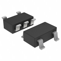
1
TSOP−5/
SOT23−5
CASE 483
xxx
A
Y
W
G
= Specific Device Code
= Assembly Location
= Year
= Work Week
= Pb−Free Package
5
xxx AYWG
G
1
(Note: Microdot may be in either location)
PIN CONNECTIONS
Reset
Output
1
Input
2
Ground
3
5 CD
4 N.C.
(Top View)
ORDERING INFORMATION
See detailed ordering and shipping information in the ordering
information section on page 22 of this data sheet.
Typical Applications
•
•
•
•
Microprocessor Reset Controller
Low Battery Detection
Power Fail Indicator
Battery Backup Detection
© Semiconductor Components Industries, LLC, 2014
August, 2021 − Rev. 27
1
Publication Order Number:
NCP302/D
�NCP302, NCP303
NCP303LSNxxT1
Open Drain Output Configuration
NCP302xSNxxT1
Complementary Output Configuration
2
Input
2
RD
Reset Output
RD
Reset
Output
*
GND 5
1
1
Vref
3
Input
Vref
CD
3
GND 5
CD
* Inverter for active low devices.
* Buffer for active high devices.
This device contains 28 active transistors.
Figure 1. Representative Block Diagrams
MAXIMUM RATINGS
Rating
Symbol
Value
Unit
Vin
12
V
Delay Capacitor Pin Voltage (Pin 5)
VCD
−0.3 to Vin + 0.3
V
Output Voltage (Pin 1)
Complementary, NCP302
N−Channel Open Drain, NCP303
VOUT
Output Current (Pin 1) (Note 2)
IOUT
70
mA
Thermal Resistance Junction−to−Air
RqJA
250
°C/W
Maximum Junction Temperature
TJ
+150
°C
Operating Ambient Temperature Range
All Voltage Options: 0.9 V to 1.1 V
All Voltage Options: 1.2 V to 4.9 V
TA
TA
−40 to +85
−40 to +125
°C
°C
Storage Temperature Range
Tstg
−55 to +150
°C
MSL
1
Input Power Supply Voltage (Pin 2)
Moisture Sensitivity Level
Latchup Performance (Note 3)
Positive
Negative
ILATCHUP
−0.3 to Vin + 0.3
−0.3 to 12
200
200
V
mA
Stresses exceeding those listed in the Maximum Ratings table may damage the device. If any of these limits are exceeded, device functionality
should not be assumed, damage may occur and reliability may be affected.
1. This device series contains ESD protection and exceeds the following tests:
Human Body Model 2000 V per MIL−STD−883, Method 3015.
Machine Model Method 200 V.
2. The maximum package power dissipation limit must not be exceeded.
P
D
+
T
*T
J(max)
A
R
qJA
3. Maximum ratings per JEDEC standard JESD78.
www.onsemi.com
2
�NCP302, NCP303
ELECTRICAL CHARACTERISTICS (For all values TA = −40°C to +125°C, unless otherwise noted.)
Characteristic
Symbol
Min
Typ
Max
Unit
Detector Threshold (Pin 2, Vin Decreasing)
VDET−
0.882
0.900
0.918
V
Detector Threshold Hysteresis (Pin 2, Vin Increasing)
VHYS
0.027
0.045
0.063
NCP302/3 − 0.9 (TA = 255C for voltage options from 0.9 to 1.1 V)
Supply Current (Pin 2)
(Vin = 0.8 V)
(Vin = 2.9 V)
Iin
−
−
0.20
0.45
0.6
1.2
V
mA
Maximum Operating Voltage (Pin 2)
Vin(max)
−
−
10
V
Minimum Operating Voltage (Pin 2)
(TA = −40°C to 85°C)
Vin(min)
−
−
0.55
0.65
0.70
0.80
V
Reset Output Current (Pin 1, Active Low ‘L’ Suffix Devices)
IOUT
Nch Sink Current, NCP302, NCP303
(VOUT = 0.05V, Vin = 0.70V)
(VOUT = 0.50V, Vin = 0.85V)
Pch Source Current, NCP302
(VOUT = 2.4V, Vin = 4.5V)
Reset Output Current (Pin 1, Active High ‘H’ Suffix Devices)
mA
0.01
0.05
0.05
0.50
−
−
1.0
6.0
−
IOUT
mA
Nch Sink Current, NCP302, NCP303
(VOUT = 0.5 V, Vin = 1.5 V)
1.05
2.5
−
Pch Source Current, NCP302
(VOUT = 0.4 V, Vin = 0.7 V)
(VOUT = GND, Vin = 0.8 V)
0.011
0.014
0.04
0.08
−
−
0.50
0.67
0.84
2.0
10
120
300
−
−
CD Delay Pin Threshold Voltage (Pin 5)
(Vin = 0.99 V)
VTCD
V
Delay Capacitor Pin Sink Current (Pin 5)
(Vin = 0.7 V, VCD = 0.1V)
(Vin = 0.85 V, VCD = 0.5V)
ICD
Delay Pullup Resistance (Pin 5)
RD
0.5
1.0
2.0
MW
Detector Threshold (Pin 2, Vin Decreasing) (TA = 25°C)
(TA = −40°C to 125°C)
VDET−
1.764
1.746
1.800
−
1.836
1.854
V
Detector Threshold Hysteresis (Pin 2, Vin Increasing)
VHYS
0.054
0.090
0.126
V
−
−
0.23
0.48
0.7
1.3
mA
NCP302/3 − 1.8
Supply Current (Pin 2)
(Vin = 1.7 V)
(Vin = 3.8 V)
Iin
mA
Maximum Operating Voltage (Pin 2)
Vin(max)
−
−
10
V
Minimum Operating Voltage (Pin 2) (TA = 25°C)
(TA = −40°C to 125°C)
Vin(min)
−
−
0.55
0.65
0.70
0.80
V
Reset Output Current (Pin 1, Active Low ‘L’ Suffix Devices)
IOUT
mA
Nch Sink Current, NCP302, NCP303
(VOUT = 0.05V, Vin = 0.70V)
(VOUT = 0.50V, Vin = 1.5V)
0.01
1.0
0.05
2.0
−
−
Pch Source Current, NCP302
(VOUT = 2.4V, Vin = 4.5V)
1.0
6.0
−
Reset Output Current (Pin 1, Active High ‘H’ Suffix Devices)
IOUT
Nch Sink Current, NCP302, NCP303
(VOUT = 0.5 V, Vin = 5.0 V)
Pch Source Current, NCP302
(VOUT = 0.4 V, Vin = 0.7 V)
(VOUT = GND, Vin = 1.5 V)
CD Delay Pin Threshold Voltage (Pin 5)
(Vin = 1.98 V)
VTCD
www.onsemi.com
3
mA
6.3
11
−
0.011
0.525
0.04
0.6
−
−
0.99
1.34
1.68
V
�NCP302, NCP303
ELECTRICAL CHARACTERISTICS (continued) (For all values TA = −40°C to +125°C, unless otherwise noted.)
Characteristic
Symbol
Min
Typ
Max
2.0
200
120
1600
−
−
Unit
NCP302/3 − 1.8
Delay Capacitor Pin Sink Current (Pin 5)
(Vin = 0.7 V, VCD = 0.1V)
(Vin = 1.5 V, VCD = 0.5V)
ICD
Delay Pullup Resistance (Pin 5)
RD
0.5
1.0
2.0
MW
Detector Threshold (Pin 2, Vin Decreasing) (TA = 25°C)
(TA = −40°C to 125°C)
VDET−
1.96
1.94
2.00
−
2.04
2.06
V
Detector Threshold Hysteresis (Pin 2, Vin Increasing)
VHYS
0.06
0.10
0.14
V
−
−
0.23
0.48
0.8
1.3
mA
NCP302/3 − 2.0
Supply Current (Pin 2)
(Vin = 1.9 V)
(Vin = 4.0 V)
Iin
mA
Maximum Operating Voltage (Pin 2)
Vin(max)
−
−
10
V
Minimum Operating Voltage (Pin 2) (TA = 25°C)
(TA = −40°C to 125°C)
Vin(min)
−
−
0.55
0.65
0.70
0.80
V
Reset Output Current (Pin 1, Active Low ‘L’ Suffix Devices)
IOUT
mA
Nch Sink Current, NCP302, NCP303
(VOUT = 0.05V, Vin = 0.70V)
(VOUT = 0.50V, Vin = 1.5V)
0.01
1.0
0.14
3.5
−
−
Pch Source Current, NCP302
(VOUT = 2.4V, Vin = 4.5V)
1.0
9.7
−
Reset Output Current (Pin 1, Active High ‘H’ Suffix Devices)
IOUT
Nch Sink Current, NCP302, NCP303
(VOUT = 0.5 V, Vin = 5.0 V)
Pch Source Current, NCP302
(VOUT = 0.4 V, Vin = 0.7 V)
(VOUT = GND, Vin = 1.5 V)
mA
6.3
11
−
0.011
0.525
0.04
0.6
−
−
1.10
1.49
1.87
2.0
200
250
3600
−
−
CD Delay Pin Threshold Voltage (Pin 5)
(Vin = 2.2 V)
VTCD
V
Delay Capacitor Pin Sink Current (Pin 5)
(Vin = 0.7 V, VCD = 0.1V)
(Vin = 1.5 V, VCD = 0.5V)
ICD
Delay Pullup Resistance (Pin 5)
RD
0.5
1.0
2.0
MW
Detector Threshold (Pin 2, Vin Decreasing) (TA = 25°C)
(TA = −40°C to 125°C)
VDET−
2.646
2.619
2.700
−
2.754
2.781
V
Detector Threshold Hysteresis (Pin 2, Vin Increasing)
VHYS
0.081
0.135
0.189
mA
NCP302/3− 2.7
Supply Current (Pin 2)
(Vin = 2.6 V)
(Vin = 4.7 V)
Iin
−
−
0.25
0.50
0.8
1.3
V
mA
Maximum Operating Voltage (Pin 2)
Vin(max)
−
−
10
V
Minimum Operating Voltage (Pin 2) (TA = 25°C)
(TA = −40°C to 125°C)
Vin(min)
−
−
0.55
0.65
0.70
0.80
V
Reset Output Current (Pin 1, Active Low ‘L’ Suffix Devices)
IOUT
mA
Nch Sink Current, NCP302, NCP303
(VOUT = 0.05V, Vin = 0.70V)
(VOUT = 0.50V, Vin = 1.5V)
0.01
1.0
0.14
3.5
−
−
Pch Source Current, NCP302
(VOUT = 2.4V, Vin = 4.5V)
1.0
9.7
−
Reset Output Current (Pin 1, Active High ‘H’ Suffix Devices)
IOUT
Nch Sink Current, NCP302, NCP303
(VOUT = 0.5 V, Vin = 5.0 V)
mA
6.3
www.onsemi.com
4
11
−
�NCP302, NCP303
ELECTRICAL CHARACTERISTICS (continued) (For all values TA = −40°C to +125°C, unless otherwise noted.)
Characteristic
Symbol
Min
Typ
Max
0.011
0.525
0.04
0.6
−
−
1.49
2.01
2.53
2.0
200
250
3600
−
−
Unit
NCP302/3− 2.7
Pch Source Current, NCP302
(VOUT = 0.4 V, Vin = 0.7 V)
(VOUT = GND, Vin = 1.5 V)
CD Delay Pin Threshold Voltage (Pin 5)
(Vin = 2.97 V)
VTCD
V
Delay Capacitor Pin Sink Current (Pin 5)
(Vin = 0.7 V, VCD = 0.1V)
(Vin = 1.5 V, VCD = 0.5V)
ICD
Delay Pullup Resistance (Pin 5)
RD
0.5
1.0
2.0
MW
Detector Threshold (Pin 2, Vin Decreasing) (TA = 25°C)
(TA = −40°C to 125°C)
VDET−
2.94
2.91
3.00
−
3.06
3.09
V
Detector Threshold Hysteresis (Pin 2, Vin Increasing)
VHYS
0.09
0.15
0.21
V
−
−
0.25
0.50
0.9
1.3
mA
NCP302/3 − 3.0
Supply Current (Pin 2)
(Vin = 2.87 V)
(Vin = 5.0 V)
Iin
mA
Maximum Operating Voltage (Pin 2)
Vin(max)
−
−
10
V
Minimum Operating Voltage (Pin 2) (TA = 25°C)
(TA = −40°C to 125°C)
Vin(min)
−
−
0.55
0.65
0.70
0.80
V
Reset Output Current (Pin 1, Active Low ‘L’ Suffix Devices)
IOUT
mA
Nch Sink Current, NCP302, NCP303
(VOUT = 0.05V, Vin = 0.70V)
(VOUT = 0.50V, Vin = 1.5V)
0.01
1.0
0.14
3.5
−
−
Pch Source Current, NCP302
(VOUT = 2.4V, Vin = 4.5V)
1.0
9.7
−
Reset Output Current (Pin 1, Active High ‘H’ Suffix Devices)
IOUT
Nch Sink Current, NCP302, NCP303
(VOUT = 0.5 V, Vin = 5.0 V)
Pch Source Current, NCP302
(VOUT = 0.4 V, Vin = 0.7 V)
(VOUT = GND, Vin = 1.5 V)
mA
6.3
11
−
0.011
0.525
0.04
0.6
−
−
1.65
2.23
2.81
2.0
200
250
3600
−
−
CD Delay Pin Threshold Voltage (Pin 5)
(Vin = 3.3 V)
VTCD
V
Delay Capacitor Pin Sink Current (Pin 5)
(Vin = 0.7 V, VCD = 0.1V)
(Vin = 1.5 V, VCD = 0.5V)
ICD
Delay Pullup Resistance (Pin 5)
RD
0.5
1.0
2.0
MW
Detector Threshold (Pin 2, Vin Decreasing) (TA = 25°C)
(TA = −40°C to 125°C)
VDET−
4.410
4.365
4.500
−
4.590
4.635
V
Detector Threshold Hysteresis (Pin 2, Vin Increasing)
VHYS
0.135
0.225
0.315
V
−
−
0.33
0.52
1.0
1.4
mA
NCP302/3 − 4.5
Supply Current (Pin 2)
(Vin = 4.34 V)
(Vin = 6.5 V)
Iin
mA
Maximum Operating Voltage (Pin 2)
Vin(max)
−
−
10
V
Minimum Operating Voltage (Pin 2) (TA = 25°C)
(TA = −40°C to 125°C)
Vin(min)
−
−
0.55
0.65
0.70
0.80
V
Reset Output Current (Pin 1, Active Low ‘L’ Suffix Devices)
IOUT
Nch Sink Current, NCP302, NCP303
(VOUT = 0.05V, Vin = 0.70V)
(VOUT = 0.50V, Vin = 1.5V)
mA
0.01
1.0
www.onsemi.com
5
0.05
2.0
−
−
�NCP302, NCP303
ELECTRICAL CHARACTERISTICS (continued) (For all values TA = −40°C to +125°C, unless otherwise noted.)
Characteristic
Symbol
Min
Typ
Max
1.5
10.5
−
Unit
NCP302/3 − 4.5
Pch Source Current, NCP302
(VOUT = 5.9V, Vin = 8.0V)
Reset Output Current (Pin 1, Active High ‘H’ Suffix Devices)
IOUT
Nch Sink Current, NCP302, NCP303
(VOUT = 0.5 V, Vin = 5.0 V)
Pch Source Current, NCP302
(VOUT = 0.4 V, Vin = 0.7 V)
(VOUT = GND, Vin = 1.5 V)
mA
6.3
11
−
0.011
0.525
0.04
0.6
−
−
2.25
3.04
3.83
2.0
200
120
1600
−
−
CD Delay Pin Threshold Voltage (Pin 5)
(Vin = 4.95 V)
VTCD
V
Delay Capacitor Pin Sink Current (Pin 5)
(Vin = 0.7 V, VCD = 0.1V)
(Vin = 1.5 V, VCD = 0.5V)
ICD
Delay Pullup Resistance (Pin 5)
RD
0.5
1.0
2.0
MW
Detector Threshold (Pin 2, Vin Decreasing) (TA = 25°C)
(TA = −40°C to 125°C)
VDET−
4.606
4.559
4.700
−
4.794
4.841
V
Detector Threshold Hysteresis (Pin 2, Vin Increasing)
VHYS
0.141
0.235
0.329
V
−
−
0.34
0.53
1.0
1.4
mA
NCP302/3 − 4.7
Supply Current (Pin 2)
(Vin = 4.54 V)
(Vin = 6.7 V)
Iin
mA
Maximum Operating Voltage (Pin 2)
Vin(max)
−
−
10
V
Minimum Operating Voltage (Pin 2) (TA = 25°C)
(TA = −40°C to 125°C)
Vin(min)
−
−
0.55
0.65
0.70
0.80
V
Reset Output Current (Pin 1, Active Low ‘L’ Suffix Devices)
IOUT
mA
Nch Sink Current, NCP302, NCP303
(VOUT = 0.05V, Vin = 0.70V)
(VOUT = 0.50V, Vin = 1.5V)
0.01
1.0
0.05
2.0
−
−
Pch Source Current, NCP302
(VOUT = 5.9V, Vin = 8.0V)
1.5
10.5
−
Reset Output Current (Pin 1, Active High ‘H’ Suffix Devices)
IOUT
Nch Sink Current, NCP302, NCP303
(VOUT = 0.5 V, Vin = 5.0 V)
Pch Source Current, NCP302
(VOUT = 0.4 V, Vin = 0.7 V)
(VOUT = GND, Vin = 1.5 V)
CD Delay Pin Threshold Voltage (Pin 5)
(Vin = 5.17 V)
VTCD
Delay Capacitor Pin Sink Current (Pin 5)
(Vin = 0.7 V, VCD = 0.1V)
(Vin = 1.5 V, VCD = 0.5V)
ICD
Delay Pullup Resistance (Pin 5)
RD
mA
6.3
11
−
0.011
0.525
0.04
0.6
−
−
2.59
3.49
4.40
2.0
200
120
1600
−
−
0.5
1.0
2.0
V
mA
MW
Product parametric performance is indicated in the Electrical Characteristics for the listed test conditions, unless otherwise noted. Product
performance may not be indicated by the Electrical Characteristics if operated under different conditions.
www.onsemi.com
6
�NCP302, NCP303
NCP302L
NCP303L
VDET+ + 2.0 V
VDET+ + 2.0 V
0.7 V
0.7 V
GND
GND
Input Voltage,
Pin 2
Reset Output
Voltage, Pin 1
VDET+ + 2.0 V
5.0 V
VDET+ + 2.0 V
2
2.5 V
GND
GND
tD1
tD2
tD1
tD2
NCP302 and NCP303 series are measured with a 10 pF capacitive load. NCP303 has an additional 470 k pullup resistor
connected from the reset output to +5.0 V. The reset output voltage waveforms are shown for the active low ‘L’ devices. Output
time delay tD1 and tD2 are dependent upon the delay capacitance. Refer to Figures 30, 31, and 32. The upper detector
threshold, VDET+ is the sum of the lower detector threshold, VDET− plus the input hysteresis, VHYS.
Figure 2. Measurement Conditions for tD1 and tD2
www.onsemi.com
7
�NCP302, NCP303
Table 1. ELECTRICAL CHARACTERISTIC TABLE FOR 0.9 − 4.9 V
NCP302 Series
Detector Threshold
Detector Threshold
Hysteresis
Vin Low
Vin High
Vin Low
Vin High
Pch
Source
Current
VHYS (V)
Iin (mA)
(Note 5)
Iin (mA)
(Note 6)
IOUT (mA)
(Note 7)
IOUT (mA)
(Note 8)
IOUT(mA)
(Note 9)
VDET− (V) (Note 4)
Part Number
Supply Current
Nch Sink Current
Min
Typ
Max
Min
Typ
Max
Typ
Typ
Typ
Typ
Typ
NCP302LSN09T1
0.882
0.9
0.918
0.027
0.045
0.063
0.20
0.45
0.05
0.5
2.0
NCP302LSN15T1
1.470
1.5
1.530
0.045
0.075
0.105
NCP302LSN18T1
1.764
1.8
1.836
0.054
0.090
0.126
0.23
0.48
NCP302LSN20T1
1.960
2.0
2.040
0.060
0.100
0.140
NCP302LSN27T1
2.646
2.7
2.754
0.081
0.135
0.189
0.25
0.50
NCP302LSN30T1,
2.940
3.0
3.060
0.090
0.150
0.210
NCV302LSN30T1,
2.940
3.0
3.060
0.090
0.150
0.210
NCP302LSN33T1
3.234
3.3
3.366
0.099
0.165
0.231
NCP302LSN38T1
3.724
3.8
3.876
0.114
0.190
0.266
NCP302LSN40T1
3.920
4.0
4.080
0.120
0.200
0.280
NCP302LSN43T1
4.214
4.3
4.386
0.129
0.215
0.301
NCP302LSN45T1
4.410
4.5
4.590
0.135
0.225
0.315
0.33
0.52
NCP302LSN47T1
4.606
4.7
4.794
0.141
0.235
0.329
0.34
0.53
3.0
4. Values shown apply at +25°C only. For voltage options greater than 1.1 V, VDET− limits over operating temperature range (−40°C to +125°C)
are VNOM ±3%. For voltage options < 1.2 V, VDET− is guaranteed only at +25°C.
5. Condition 1: 0.9 — 2.9 V, Vin = VDET− − 0.10 V; 3.0 — 3.9 V, Vin = VDET− − 0.13 V; 4.0 — 4.9 V, Vin = VDET− − 0.16 V
6. Condition 2: 0.9 — 4.9 V, Vin = VDET− + 2.0 V
7. Condition 3: 0.9 — 4.9 V, Vin = 0.7 V, VOUT = 0.05 V, Active Low ‘L’ Suffix Devices
8. Condition 4: 0.9 — 1.0 V, Vin = 0.85 V, VOUT = 0.5 V; 1.1 — 1.5 V, Vin = 1.0 V, VOUT = 0.5 V; 1.6 — 4.9 V, Vin = 1.5 V, VOUT = 0.5 V,
Condition 4: Active Low ‘L’ Suffix Devices
9. Condition 5: 0.9 — 3.9 V, Vin = 4.5 V, VOUT = 2.4 V; 4.0 — 4.9 V, Vin = 8.0 V, VOUT = 5.9 V, Active Low ‘L’ Suffix Devices
Table 2. ELECTRICAL CHARACTERISTIC TABLE FOR 0.9 − 4.9 V
NCP302 Series
Part Number
Supply Current
Detector Threshold
Detector Threshold
Hysteresis
Vin Low
Vin High
Nch Sink
Current
VDET− (V) (Note 10)
VHYS (V)
Iin (mA)
(Note 11)
Iin (mA)
(Note 12)
Pch Source Current
Vin Low
Vin High
IOUT (mA)
(Note 13)
IOUT (mA)
(Note 14)
IOUT (mA)
(Note 15)
Min
Typ
Max
Min
Typ
Max
Typ
Typ
Typ
Typ
Typ
NCP302HSN09T1
0.882
0.9
0.918
0.027
0.045
0.063
0.20
0.45
2.5
0.04
0.08
NCP302HSN18T1
1.764
1.8
1.836
0.054
0.090
0.126
0.23
0.48
NCP302HSN27T1
2.646
2.7
2.754
0.081
0.135
0.189
0.25
0.50
NCP302HSN30T1
2.940
3.0
3.060
0.090
0.150
0.210
NCP302HSN40T1
3.920
4.0
4.080
0.120
0.200
0.280
NCP302HSN45T1
4.410
4.5
4.590
0.135
0.225
0.315
0.33
0.52
10. Values shown apply at +25°C only. For voltage options greater than 1.1 V, VDET− limits over operating temperature range (−40°C to +125°C)
are VNOM ±3%. For voltage options < 1.2 V, VDET− is guaranteed only at +25°C.
11. Condition 1: 0.9 — 2.9 V, Vin = VDET− − 0.10 V; 3.0 — 3.9 V, Vin = VDET− − 0.13 V; 4.0 — 4.9 V, Vin = VDET− − 0.16 V
12. Condition 2: 0.9 — 4.9 V, Vin = VDET− + 2.0 V
13. Condition 3: 0.9 — 1.4 V, Vin = 1.5 V, VOUT = 0.5 V; 1.5 — 4.9 V, Vin = 5.0 V, VOUT = 0.5 V, Active High ‘H’ Suffix Devices
14. Condition 4: 0.9 — 4.9 V, Vin = 0.7 V, VOUT = 0.4 V, Active High ‘H’ Suffix Devices
15. Condition 5: 0.9 — 1.0 V, Vin = 0.8 V, VOUT = GND; 1.1 — 1.5 V, Vin = 1.0 V, VOUT = GND; 1.6 — 4.9 V, Vin = 1.5 V, VOUT = GND,
Active High ‘H’ Suffix Devices
www.onsemi.com
8
�NCP302, NCP303
Table 3. ELECTRICAL CHARACTERISTIC TABLE FOR 0.9 − 4.9 V
NCP303 Series
Detector Threshold
Nch Sink Current
Vin Low
Vin High
Vin Low
Vin High
VHYS (V)
Iin (mA)
(Note 17)
Iin (mA)
(Note 18)
IOUT (mA)
(Note 19)
IOUT (mA)
(Note 20)
VDET− (V) (Note 16)
Part Number
Supply Current
Detector Threshold
Hysteresis
Min
Typ
Max
Min
Typ
Max
Typ
Typ
Typ
Typ
NCP303LSN09T1
0.882
0.9
0.918
0.027
0.045
0.063
0.20
0.45
0.05
0.5
NCP303LSN10T1
0.980
1.0
1.020
0.030
0.050
0.070
NCP303LSN11T1
1.078
1.1
1.122
0.033
0.055
0.077
NCP303LSN13T1
1.274
1.3
1.326
0.039
0.065
0.091
NCP303LSN14T1
1.372
1.4
1.428
0.042
0.070
0.098
NCP303LSN15T1
1.470
1.5
1.530
0.045
0.075
0.105
NCP303LSN16T1
1.568
1.6
1.632
0.048
0.080
0.112
NCP303LSN17T1
1.666
1.7
1.734
0.051
0.085
0.119
NCP303LSN18T1
1.764
1.8
1.836
0.054
0.090
0.126
NCP303LSN20T1
1.960
2.0
2.040
0.060
0.100
0.140
NCP303LSN22T1
2.156
2.2
2.244
0.066
0.110
0.154
NCP303LSN23T1
2.254
2.3
2.346
0.069
0.115
0.161
NCP303LSN24T1
2.352
2.4
2.448
0.072
0.120
0.168
NCP303LSN25T1
2.450
2.5
2.550
0.075
0.125
0.175
NCP303LSN26T1
2.548
2.6
2.652
0.078
0.130
0.182
NCP303LSN27T1
2.646
2.7
2.754
0.081
0.135
0.189
NCP303LSN28T1
2.744
2.8
2.856
0.084
0.140
0.196
NCP303LSN29T1
2.842
2.9
2.958
0.087
0.145
0.203
NCP303LSN30T1
2.940
3.0
3.060
0.090
0.150
0.210
NCP303LSN31T1
3.038
3.1
3.162
0.093
0.155
0.217
NCP303LSN32T1
3.136
3.2
3.264
0.096
0.160
0.224
NCP303LSN33T1
3.234
3.3
3.366
0.099
0.165
0.231
NCP303LSN34T1
3.332
3.4
3.468
0.102
0.170
0.238
NCP303LSN36T1
3.528
3.6
3.672
0.108
0.180
0.252
NCP303LSN38T1
3.724
3.8
3.876
0.114
0.190
0.266
NCP303LSN40T1
3.920
4.0
4.080
0.120
0.200
0.280
NCP303LSN42T1
4.116
4.2
4.284
0.126
0.210
0.294
NCP303LSN44T1
4.312
4.4
4.488
0.132
0.220
0.308
NCP303LSN45T1
4.410
4.5
4.590
0.135
0.225
0.315
NCP303LSN46T1
4.508
4.6
4.692
0.138
0.230
0.322
NCP303LSN47T1
4.606
4.7
4.794
0.141
0.235
0.329
NCP303LSN49T1
4.802
4.9
4.998
0.147
0.245
0.343
1.0
2.0
0.23
0.48
0.25
0.50
0.33
0.52
0.34
0.53
16. Values shown apply at +25°C only. For voltage options greater than 1.1 V, VDET− limits over operating temperature range (−40°C to +125°C)
are VNOM ±3%. For voltage options < 1.2 V, VDET− is guaranteed only at +25°C.
17. Condition 1: 0.9 — 2.9 V, Vin = VDET− − 0.10 V; 3.0 — 3.9 V, Vin = VDET− − 0.13 V; 4.0 — 4.9 V, Vin = VDET− − 0.16 V
18. Condition 2: 0.9 — 4.9 V, Vin = VDET− + 2.0 V
19. Condition 3: 0.9 — 4.9 V, Vin = 0.7 V, VOUT = 0.05 V, Active Low ‘L’ Suffix Devices
20. Condition 4: 0.9 — 1.0 V, Vin = 0.85 V, VOUT = 0.5 V; 1.1 — 1.5 V, Vin = 1.0 V, VOUT = 0.5 V; 1.6 — 4.9 V, Vin = 1.5 V, VOUT = 0.5 V,
Condition 4: Active Low ‘L’ Suffix Devices
www.onsemi.com
9
�NCP302, NCP303
1.0
10.5
0.9
0.8
Iin, INPUT CURRENT (mA)
Iin, INPUT CURRENT (mA)
TA = 25°C
TA = 25°C
0.7
0.6
0.5
0.4
0.3
0.2
0.1
0
0
2.0
4.0
6.0
10
8.0
2.5
2.0
1.5
1.0
0.5
0
12
0
2.0
Vin, INPUT VOLTAGE (V)
Figure 3. NCP302/3 Series 0.9 V
Input Current vs. Input Voltage
VDET, DETECTOR THRESHOLD VOLTAGE (V)
Iin, INPUT CURRENT (mA)
TA = 25°C
2.5
2.0
1.5
1.0
0.5
0
2.0
4.0
8.0
6.0
10
12
Vin, INPUT VOLTAGE (V)
0.95
VDET+
2.75
2.70
VDET−
−25
0
25
50
75
100
TA, AMBIENT TEMPERATURE (°C)
125
VDET, DETECTOR THRESHOLD VOLTAGE (V)
VDET, DETECTOR THRESHOLD VOLTAGE (V)
2.85
2.60
−50
VDET+
0.90
VDET−
0.85
0.80
−50
0
−25
25
75
50
100
TA, AMBIENT TEMPERATURE (°C)
Figure 6. NCP302/3 Series 0.9 V
Detector Threshold Voltage vs. Temperature
2.90
2.65
12
1.00
Figure 5. NCP302/3 Series 4.5 V
Input Current vs. Input Voltage
2.80
10
Figure 4. NCP302/3 Series 2.7 V
Input Current vs. Input Voltage
17.2
0
6.0
4.0
8.0
Vin, INPUT VOLTAGE (V)
4.9
4.8
VDET+
4.7
4.6
4.5
VDET−
4.4
4.3
−50
Figure 7. NCP302/3 Series 2.7 V
Detector Threshold Voltage vs. Temperature
−25
0
25
50
75
100
TA, AMBIENT TEMPERATURE (°C)
Figure 8. NCP302/3 Series 4.5 V
Detector Threshold Voltage vs. Temperature
www.onsemi.com
10
125
�NCP302, NCP303
3.5
VOUT, OUTPUT VOLTAGE (V)
VOUT, OUTPUT VOLTAGE (V)
1.0
0.8
0.6
TA = −40°C (303L only)
0.4
TA = 25°C (303L only)
0.2
0
3.0
2.5
2.0
1.5
TA = 125°C (303L only)
1.0
TA = −40°C (303L only)
0.5
TA = 25°C (303L only)
0
0
0.4
0.6
Vin, INPUT VOLTAGE (V)
0.2
0.8
1.0
0
Figure 9. NCP302L/3L Series 0.9 V
Reset Output Voltage vs. Input Voltage
IOUT, OUTPUT SINK CURRENT (mA)
VOUT, OUTPUT VOLTAGE (V)
1.6
5.0
4.0
3.0
TA = −40°C (303L only)
TA = 25°C (303L only)
1.0
0
0
1.0
2.0
4.0
3.0
Vin, INPUT VOLTAGE (V)
5.0
6.0
TA = −40°C
1.2
1.0
0.8
0.6
TA = 25°C
0.4
TA = 85°C
0.2
0
0
0.4
0.2
0.6
0.8
1.0
Vin, INPUT VOLTAGE (V)
Figure 12. NCP302H/3L Series 0.9 V
Reset Output Sink Current vs. Input Voltage
12
20
VOUT = 0.5 V
10
IOUT, OUTPUT SINK CURRENT (mA)
IOUT, OUTPUT SINK CURRENT (mA)
3.5
VOUT = 0.5 V
1.4
Figure 11. NCP302L/3L Series 4.5 V
Reset Output Voltage vs. Input Voltage
TA = −40°C
8.0
6.0
TA = 25°C
4.0
TA = 125°C
2.0
0
3.0
Figure 10. NCP302L/3L Series 2.7 V
Reset Output Voltage vs. Input Voltage
6.0
2.0
1.5
2.5
1.0
2.0
Vin, INPUT VOLTAGE (V)
0.5
0
0.5
1.0
1.5
2.0
2.5
3.0
VOUT = 0.5 V
TA = −40°C
15
10
TA = 25°C
TA = 125°C
5.0
0
0
1.0
2.0
3.0
4.0
Vin, INPUT VOLTAGE (V)
Vin, INPUT VOLTAGE (V)
Figure 13. NCP302H/3L Series 2.7 V
Reset Output Sink Current vs. Input Voltage
Figure 14. NCP302H/3L Series 4.5 V
Reset Output Sink Current vs. Input Voltage
www.onsemi.com
11
5.0
�20
VOUT = Vin −2.1 V
TA = 25°C
IOUT, OUTPUT SOURCE CURRENT (mA)
IOUT, OUTPUT SOURCE CURRENT (mA)
NCP302, NCP303
15
Vin −1.5 V
10
Vin −1.0 V
5.0
Vin −0.5 V
0
0
2.0
4.0
8.0
6.0
10
20
VOUT = Vin −2.1 V
TA = 25°C
15
Vin −1.5 V
Vin −1.0 V
10
Vin −0.5 V
5.0
0
0
4.0
2.0
TA = 25°C
VOUT = Vin −2.1 V
15
Vin −1.5 V
10
Vin −1.0 V
5.0
Vin −0.5 V
0
0
2.0
4.0
8.0
6.0
1.5
TA = 25°C
1.0
Vin = 0.85 V
0.5
Vin = 0.7 V
0
10
0
IOUT, OUTPUT SINK CURRENT (mA)
IOUT, OUTPUT SINK CURRENT (mA)
35
Vin = 2.5 V
10
Vin = 2.0 V
5.0
Vin = 1.5 V
0
1.0
0.8
1.0
Figure 18. NCP302H/3L Series 0.9 V
Reset Output Sink Current vs. Output Voltage
15
0.5
0.6
VOUT, OUTPUT VOLTAGE (V)
Figure 17. NCP302L Series 4.5 V
Reset Output Source Current vs. Input Voltage
0
0.4
0.2
Vin, INPUT VOLTAGE (V)
TA = 25°C
10
Figure 16. NCP302L Series 2.7 V
Reset Output Source Current vs. Input Voltage
IOUT, OUTPUT SINK CURRENT (mA)
IOUT, OUTPUT SOURCE CURRENT (mA)
Figure 15. NCP302L Series 0.9 V
Reset Output Source Current vs. Input Voltage
20
8.0
6.0
Vin, INPUT VOLTAGE (V)
Vin, INPUT VOLTAGE (V)
1.5
2.0
2.5
TA = 25°C
30
Vin = 4.0 V
25
Vin = 3.5 V
20
Vin = 3.0 V
15
Vin = 2.5 V
10
Vin = 2.0 V
5.0
0
Vin = 1.5 V
0
1.0
2.0
3.0
VOUT, OUTPUT VOLTAGE (V)
VOUT, OUTPUT VOLTAGE (V)
Figure 19. NCP302H/3L Series 2.7 V
Reset Output Sink Current vs. Output Voltage
Figure 20. NCP302H/3L Series 4.5 V
Reset Output Sink Current vs. Output Voltage
www.onsemi.com
12
4.0
�1.6
ICD, CD DELAY PIN SINK CURRENT (mA)
ICD, CD DELAY PIN SINK CURRENT (mA)
NCP302, NCP303
VCD = 0.5 V
1.4
1.2
1.0
0.8
0.6
TA = 25°C
0.4
TA = 85°C
0.2
0
0
0.4
0.2
TA = −40°C
0.6
1.0
0.8
14
VCD = 0.5 V
12
TA = −40°C
10
8.0
TA = 25°C
6.0
4.0
TA = 125°C
2.0
0
0
1.0
0.5
Vin, INPUT VOLTAGE (V)
ICD, CD DELAY PIN SINK CURRENT (mA)
TA = −40°C
12
TA = 25°C
8.0
TA = 125°C
4.0
16
1.0
2.0
3.0
5.0
4.0
1.0
Vin = 0.85 V
0.5
0
Vin = 0.7 V
0
0.2
0.4
0.6
0.8
Figure 23. NCP302/3 Series 4.5 V
CD Delay Pin Sink Current vs. Input Voltage
Figure 24. NCP302/3 Series 0.9 V
CD Delay Pin Sink Current vs. Voltage
TA = 25°C
Vin = 2.5 V
Vin = 2.0 V
8.0
Vin = 1.5 V
4.0
0
TA = 25°C
VCD, DELAY PIN VOLTAGE (V)
12
0
1.5
Vin, INPUT VOLTAGE (V)
ICD, CD DELAY PIN SINK CURRENT (mA)
ICD, CD DELAY PIN SINK CURRENT (mA)
ICD, CD DELAY PIN SINK CURRENT (mA)
VCD = 0.5 V
0
0.5
1.0
1.5
3.0
Figure 22. NCP302/3 Series 2.7 V
CD Delay Pin Sink Current vs. Input Voltage
20
0
2.5
2.0
Vin, INPUT VOLTAGE (V)
Figure 21. NCP302/3 Series 0.9 V
CD Delay Pin Sink Current vs. Input Voltage
16
1.5
2.5
2.0
40
TA = 25°C
Vin = 4.0 V
30
Vin = 3.5 V
20
Vin = 3.0 V
Vin = 2.5 V
10
0
0
1.0
2.0
3.0
VCD, DELAY PIN VOLTAGE (V)
VCD, DELAY PIN VOLTAGE (V)
Figure 26. NCP302/3 Series 4.5 V
CD Delay Pin Sink Current vs. Voltage
Figure 25. NCP302/3 Series 2.7 V
CD Delay Pin Sink Current vs. Voltage
www.onsemi.com
13
1.0
4.0
�0.9
Vin = 0.99 V
0.8
0.7
0.6
0.5
0.4
0.3
−50
−25
0
75
25
50
TA, AMBIENT TEMPERATURE (°C)
2.2
VTCD, CD PIN THRESHOLD VOLTAGE (V)
VTCD, CD PIN THRESHOLD VOLTAGE (V)
NCP302, NCP303
100
Vin = 2.97 V
2.1
2.0
1.9
1.8
1.7
−50
125
10000
3.7
TA = 25°C
Vin = 4.95 V
3.6
1000
3.5
3.4
3.3
3.2
−50
0
−25
25
50
75
100
tD1 (ms)
100
tD2 (ms)
10
1.0
0.1
0.00001
125
0.0001
0.001
0.01
0.1
1.0
CD, DELAY PIN CAPACITANCE ( mF)
TA, AMBIENT TEMPERATURE (°C)
Figure 29. NCP302/3 Series 4.5 V
CD Delay Pin Threshold Voltage vs. Temperature
Figure 30. NCP302/3 Series 0.9 V
Output Time Delay vs. Capacitance
10000
10000
TA = 25°C
1000
t D1, t D2 , OUTPUT TIME DELAY
TA = 25°C
t D1, t D2 , OUTPUT TIME DELAY
0
75
100
25
50
TA, AMBIENT TEMPERATURE (°C)
Figure 28. NCP302/3 Series 2.7 V
CD Delay Pin Threshold Voltage vs. Temperature
t D1, t D2 , OUTPUT TIME DELAY
VTCD, CD PIN THRESHOLD VOLTAGE (V)
Figure 27. NCP302/3 Series 0.9 V
CD Delay Pin Threshold Voltage vs. Temperature
−25
1000
tD1 (ms)
100
10
tD2 (ms)
1.0
0.1
0.00001
0.0001
0.001
0.01
0.1
1.0
tD1 (ms)
100
10
tD2 (ms)
1.0
0.1
0.00001
0.0001
0.001
0.01
0.1
CD, DELAY PIN CAPACITANCE ( mF)
CD, DELAY PIN CAPACITANCE ( mF)
Figure 31. NCP302/3 Series 2.7 V
Output Time Delay vs. Capacitance
Figure 32. NCP302/3 Series 4.5 V
Output Time Delay vs. Capacitance
www.onsemi.com
14
1.0
�NCP302, NCP303
160
250
tD2, OUTPUT TIME DELAY (ms)
tD2, OUTPUT TIME DELAY (ms)
CD = 0.1 mF
200
160
120
80
40
0
−50
−25
0
25
75
50
CD = 0.1 mF
140
120
100
80
60
40
20
0
−50
100
−25
Figure 33. NCP302/3 Series 0.9 V
Reset Output Time Delay vs. Temperature
50
75
100
125
1.6
RD, DELAY RESISTANCE (MW)
tD2, OUTPUT TIME DELAY (ms)
25
Figure 34. NCP302/3 Series 2.7 V
Reset Output Time Delay vs. Temperature
250
CD = 0.1 mF
200
150
100
50
0
−50
0
TA, AMBIENT TEMPERATURE (°C)
TA, AMBIENT TEMPERATURE (°C)
−25
0
25
50
75
1.2
0.8
0.4
0
−50
100
TA, AMBIENT TEMPERATURE (°C)
−25
0
25
50
75
100
TA, AMBIENT TEMPERATURE (°C)
Figure 35. NCP302/3 Series 4.5 V
Reset Output Time Delay vs. Temperature
Figure 36. NCP302/3 Series
Delay Resistance vs. Temperature
www.onsemi.com
15
125
�NCP302, NCP303
OPERATING DESCRIPTION
Vin will again return to its nominal level and become greater
than the VDET+. The voltage detector will turn off the
N−Channel MOSFET and allow pullup resistor RD to charge
external capacitor CD, thus creating a programmable delay
for releasing the reset signal. When the voltage at Pin 5
exceeds the inverter/buffer threshold, typically 0.675 Vin,
the reset output will revert back to its original state. The reset
output time delay versus capacitance is shown in Figures 30
through 32. The voltage detector and inverter/buffer have
built−in hysteresis to prevent erratic reset operation.
Although these device series are specifically designed for
use as reset controllers in portable microprocessor based
systems, they offer a cost−effective solution in numerous
applications where precise voltage monitoring and time
delay are required. Figures 38 through 46 show various
application examples.
The NCP302 and NCP303 series devices consist of a
precision voltage detector that drives a time delay generator.
Figures 37 and 38 show a timing diagram and a typical
application. Initially consider that input voltage Vin is at a
nominal level and it is greater than the voltage detector upper
threshold (VDET+). The voltage at Pin 5 and capacitor CD
will be at the same level as Vin, and the reset output (Pin 1)
will be in the high state for active low devices, or in the low
state for active high devices. If there is a power interruption
and Vin becomes significantly deficient, it will fall below the
lower detector threshold (VDET−) and the external time
delay capacitor CD will be immediately discharged by an
internal N−Channel MOSFET that connects to Pin 5. This
sequence of events causes the Reset output to be in the low
state for active low devices, or in the high state for active
high devices. After completion of the power interruption,
Input Voltage, Pin 2
Vin
VDET+
VDET−
Vin
Capacitor, Pin 5
Reset Output (Active Low), Pin 1
0.675 Vin
Vin
VDET−
0V
Reset Output (Active High), Pin 1
Vin
VDET−
0V
tD2
Figure 37. Timing Waveforms
www.onsemi.com
16
�NCP302, NCP303
APPLICATION CIRCUIT INFORMATION
VDD
2
5
CD
CD
VDD
Input
*
1
NCP302
Series
* Required for
GND
3
Microprocessor
Reset
Reset Output
GND
NCP303
Figure 38. Microprocessor Reset Circuit
2.85 V
2.70 V
Vin < 2.7 ON
2
5
CD
Input
1
NCP302
LSN27T1
To Additional Circuitry
Reset Output
Vin > 2.835 ON
3
GND
Figure 39. Battery Charge Indicator
Vsupply
5.0 V
1.0 V
0V
2
5
CD
CD
NCP303
LSN45T1
3
470 k
Input
1
Reset Output
To Additional Circuitry
0.001 mF
Missing Pulse
GND
Input
0V
Vin
[0.675*Vin
CD
Reset Output
tD2
Figure 40. Missing Pulse Detector or Frequency Detector
www.onsemi.com
17
�NCP302, NCP303
VDD
RH
2
VDD
Input
RL
5
CD
1
NCP301
NCP303
LSN27T1
Reset
Reset Output
Microprocessor
GND
3
GND
Figure 41. Microprocessor Reset Circuit with Additional Hysteresis
Comparator hysteresis can be increased with the addition of
resistor RH. The hysteresis equations have been simplified and
do not account for the change of input current Iin as Vin crosses
the comparator threshold. The internal resistance, Rin is simply
calculated using Iin = 0.26 mA at 2.6 V.
Vin Decreasing:
V th +
ǒRR
Vin Increasing:
V th +
ǒ
H
in
Ǔ
) 1 ǒV DET*Ǔ
Ǔ
RH
) 1 ǒV DET* ) V HYSǓ
R in ø R L
VHYS = Vin Increasing − Vin Decreasing
Test Data
ÁÁÁÁÁÁÁÁÁÁÁÁÁÁÁÁÁÁÁÁ
ÁÁÁÁÁÁ
ÁÁÁÁÁÁ
ÁÁÁ
ÁÁÁ
ÁÁ
ÁÁÁÁÁÁÁÁÁÁÁÁÁÁÁÁÁÁÁÁ
ÁÁÁÁÁÁÁÁÁÁÁÁÁÁÁÁÁÁÁÁ
ÁÁÁÁÁÁ
ÁÁÁÁÁÁ
ÁÁÁ
ÁÁÁ
ÁÁ
ÁÁÁÁÁÁ
ÁÁÁÁÁÁ
ÁÁÁ
ÁÁÁ
ÁÁ
ÁÁÁÁÁÁ
ÁÁÁÁÁÁ
ÁÁÁ
ÁÁÁ
ÁÁ
ÁÁÁÁÁÁÁÁÁÁÁÁÁÁÁÁÁÁÁÁ
Vth Decreasing
(V)
Vth Increasing
(V)
VHYS
(V)
RH
(W)
RL
(kW)
2.70
2.70
2.70
2.70
2.70
2.70
2.70
2.70
2.70
2.70
2.84
2.87
2.88
2.91
2.90
2.94
2.98
2.70
3.04
3.15
0.135
0.17
0.19
0.21
0.20
0.24
0.28
0.27
0.34
0.35
0
100
100
100
220
220
220
470
470
470
−
10
6.8
4.3
10
6.8
4.3
10
6.8
4.3
5.0 V
100 k
Test Data
C
2
5
CD
Input
NCP301
NCP302
HSN27T1
LSN27T1
3
C (mF)
fOSC (kHz)
IQ (mA)
0.01
2590
21.77
1
0.1
490
21.97
Reset Output
1.0
52
22.07
82 k
GND
Figure 42. Simple Clock Oscillator
www.onsemi.com
18
�NCP302, NCP303
Vsupply
Load
Rsense
2
5
CD
3
VDD
Input
NCP301
NCP303
LSN09T1
LSN27T1
This circuit monitors the current at the load. As
current flows through the load, a voltage drop with
respect to ground appears across Rsense where
Vsense = Iload * Rsense. The following conditions apply:
If:
ILoad t VDET − /Rsense
ILoad w (VDET −+VHYS)/Rsense
50 k
1
Then:
Reset Output = 0 V
Reset Output = VDD
Microcontroller
Reset Output
GND
GND
Figure 43. Microcontroller Systems Load Sensing
Vsupply
2
5
CD
5
CD
Input
NCP303
NCP301
LSN27T1
LSN45T1
3
GND
2
Input
NCP303
NCP301
LSN27T1
3
GND
2
Input
1
Reset
Output
1
Reset
Output
Vin = 1.0 V to 10 V
5
CD
NCP303
NCP301
LSN27T1
LSN18T1
3
1
Reset
Output
GND
A simple voltage monitor can be constructed by connecting several voltage detectors as shown above. Each LED will
sequentially turn on when the respective voltage detector threshold (VDET− +VHYS) is exceeded. Note that detector
thresholds (VDET−) that range from 0.9 V to 4.9 V in 100 mV steps can be manufactured.
Figure 44. LED Bar Graph Voltage Monitor
www.onsemi.com
19
�NCP302, NCP303
VDD
2
Input
EN
5
IN
CD
Logic 1
NCP302L
Series
CD
3
1
To MCU or
Logic Circuitry
Reset Output
GND
VDD
NCP302
Input Pin
VDET
0V
Logic 1
Enable
Pin
CD Pin
1
0
VDD
VTCD
0V
Reset
Output
0V
Note: Logic 1 is in tristate when EN = 0,
VTCD � 0.675 * VDD
tD2
tD2
Figure 45. Undervoltage Detection with Independent Reset Signal Control
logic gate is tristated the undervoltage detector will behave
normally. If the tristate is de−asserted, the logic gate will pull
the CD pin low resulting in the Reset Output pin changing to
an active state. This independent control is useful in power
supply sequencing applications when the Reset Output is
tied to the enable input of an LDO or DC−DC converter.
This circuit monitors VDD for undervoltage. If the VDD
input falls below the detector threshold (VDET−), then the
capacitor on the CD pin will be immediately discharged
resulting in the reset output changing to its active state
indicating that an undervoltage event has been detected. The
addition of a logic gate (Logic 1) provides for reset output
control which is independent of VDD. If the output of the
www.onsemi.com
20
�NCP302, NCP303
Power Supply 1
(System Core)
R1 is Optional CD Pin Pullup
2
R1
5
CD
CD
Input
NCP302L
Series
3.3 V Power Supply 2
(I/O Subsystem)
3
GND
2
Input
NCP301
LSN30T1
5.0 V Power Supply 3
(Peripheral Subsystem)
3
GND
2
Input
NCP301
LSN45T1
3
VP
1
*
RP
To MCU or
Logic Circuitry
Reset Output
*Required for
NCP303
1
Reset Output
1
Reset Output
GND
VIN
Power Supply 1
0V
Power Supply 2
0V
Power Supply 3
0V
CD Pin
VIN
VTCD
0V
NCP302L
RESET Output
0V
Note: VTCD � 0.675 * VIN
tD2
tD2
tD2
tD2
Figure 46. Multi−Rail Supply Undervoltage Monitor with Power Good
This circuit monitors multiple power supply rails for
undervoltage conditions. If any of the three power supplies
are in an undervoltage condition, the NCP302 reset output
will be immediately set to an active low level. All three
power supplies must be above their minimum voltage levels
for the NCP302 reset output to generate a “Power Good”
level (Reset Output = Power Supply 1 or VP).
Optionally, R1 may be added to provide a smaller
effective CD pin pullup resistance, (RD’), where
RD’ = R1 || RD, with RD (internal CD pin pullup resistance)
approximately equal to 1.0 MW, and R1 > 5 kW. If R1