NCP5623
Triple Output I2C Controlled
RGB LED Driver
The NCP5623 mixed analog circuit is a triple output LED driver
dedicated to the RGB illumination or backlight LCD display.
Features
•
•
•
•
•
•
•
http://onsemi.com
2.7 to 5.5 V Input Voltage Range
RGB Function Fully Supported
Programmable Integrated Gradual Dimming
90 mA Total LED Current Capability
Provides Three Independent LED Drives
Support I2C Protocol
This is a Pb−Free Device
MARKING
DIAGRAM
14
•
•
•
•
1
1
Typical Applications
5623
A
L
Y
W
G
Multicolor Illuminations
Portable Back Light
Digital Cellular Phone Camera Photo Flash
LCD and Key Board Simultaneous Drive
5623
ALYWG
G
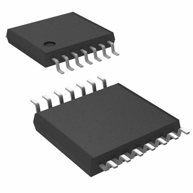
TSSOP−14
CASE 948G
14
= Specific Device Code
= Assembly Location
= Wafer Lot
= Year
= Work Week
= Pb−Free Package
(Note: Microdot may be in either location)
+Vbat
+Vcc
GND
MCU
C2
1 mF/6.3 V
13
C1
12
SDA
9
SCL
11
R1 10
I2C Port
62 k
GND
GND
6
2
+5 V
U1
NCP5623
GND
Vbat
Vdet
SDA
LED1
SCL
IREF
LED2
GND
LED3
GND
IC NC NC IC
1
7
5
6
4
2
3
5
8 14
1 mF/6.3 V
D1
ORDERING INFORMATION
Device
R
G
B
Package
Shipping†
TSSOP−14
(Pb−Free)
2500 /
Tape & Reel
1
NCP5623DTBR2G
3
†For information on tape and reel specifications,
including part orientation and tape sizes, please
refer to our Tape and Reel Packaging Specification
Brochure, BRD8011/D.
4
LRTB−G6T
Figure 1. Typical Multiple Color LED Driver
© Semiconductor Components Industries, LLC, 2008
October, 2008 − Rev. 6
1
Publication Order Number:
NCP5623/D
�NCP5623
TSSOP−14
14 IC
IC 1
GND 2
13 Vbat
LED3 3
12 Vdet
LED2 4
11 SCL
LED1 5
10 IREF
GND 6
9 SDA
8 NC
NC 7
(Top View)
Figure 2. Pin Assignments
12
7
8
14
NC
NC
IC
+5 V
Vbat
1 mF/6.3 V
GND
1
IC
C2
1.0 mF/6.3 V
13
NCP5623
C1
6
GND
SDA
SCL
9
62 k
GND
D3
LED3
3
11
GND
Vbat
R1
Vbat
DIGITAL CONTROL
10
LED2
4
PWM LED#1
ANALOG
FUNCTIONS
PWM LED#2
PWM LED#3
GND LED1
5
GND
CURRENT GND
MIRRORS
Figure 3. Simplified Block Diagram
http://onsemi.com
2
2
GND
D2
D1
GND
�NCP5623
PIN ASSIGNMENT
Pin
Name
1
IC
Type
Description
2
GND
POWER
This pin is the GROUND signal for the analog and digital blocks and output current control. The
pin must be connected to the system ground, a ground plane being strongly recommended.
3
LED3
OUTPUT,
POWER
This pin sinks to ground and monitors the current flowing into the BLUE LED, intended to be
used in illumination application (Note 1). The Anode of the associated LED shall be connected
to the Vbat supply.
4
LED2
OUTPUT,
POWER
This pin sinks to ground and monitors the current flowing into the GREEN LED, intended to be
used in illumination application (Note 1). The Anode of the associated LED shall be connected
to the Vbat supply.
5
LED1
OUTPUT,
POWER
This pin sinks to ground and monitors the current flowing into the RED LED, intended to be
used in illumination application (Note 1). The anode of the associated LED shall be connected
to the Vbat supply.
6
GND
ANALOG
GROUND
This pin copies the Analog Ground and shall be connected to the system ground plane.
7, 8
NC
9
SDA
INPUT,
DIGITAL
This pin carries the data provided by the I2C protocol. The content of the SDA byte is used to
program the mode of operation and to set up the output current.
10
IREF
ANALOG
This pin provides the reference current, based on the internal band−gap voltage reference, to
control the output current flowing in the LED. A 1% tolerance, or better, resistor shall be used to
get the highest accuracy of the LED current. An external current mirror can be used to bias this
pin to dynamically set up the LED maximum current.
In no case shall the voltage at IREF pin be forced either higher or lower than the 600 mV
provided by the internal reference.
11
SCL
INPUT,
DIGITAL
This pin carries the I2C clock to control the I2C communication. The SCL clock is associated
with the SDA signal.
12
Vdet
INPUT
This pin provides a DC bias to the internal circuit and must be connected to the same voltage
that the one applied to the Vbat pin 13.
13
Vbat
POWER
14
IC
This pin is internally connected. It must be left open.
This pin must be left floating with no connection.
This pin is the input Battery voltage to supply the analog and digital blocks. The pin must be
decoupled to ground by a 1 mF or higher ceramic capacitor (Note 2).
This pin is internally connected. It must be left open.
1. The maximum current is 37 mA for each LED
2. Using low ESR ceramic capacitor, X5R type, is recommended.
http://onsemi.com
3
�NCP5623
MAXIMUM RATINGS
Symbol
Vbat
SDA, SCL
Rating
Power Supply (see Figure 4)
Digital Input Voltage
Value
Unit
−0.3 < Vbat < 7.0
V
−0.3 < V < Vbat
V
ESD
Human Body Model: R = 1500 W, C = 100 pF (Note 3)
Machine Model
2
200
kV
V
PD
RqJC
RqJA
Power Dissipation @ TA = +85°C (Note 4)
Thermal Resistance Junction to Case
Thermal Resistance Junction to Air
235
46
170
mW
°C/W
°C/W
TA
Operating Ambient Temperature Range
−40 to +85
°C
TJ
Operating Junction Temperature Range
−40 to +125
°C
TJmax
Tstg
ILATCHUP
Maximum Junction Temperature
Storage Temperature Range
+150
°C
−65 to +150
°C
±100
mA
Latch−up current maximum rating per JEDEC standard: JESD78.
Stresses exceeding Maximum Ratings may damage the device. Maximum Ratings are stress ratings only. Functional operation above the
Recommended Operating Conditions is not implied. Extended exposure to stresses above the Recommended Operating Conditions may affect
device reliability.
Moisture Sensitivity Level (MSL): 1 per IPC/JEDEC standard: J−STD−020A.
3. This device series contains ESD protection and exceeds the following tests:
Human Body Model (HBM) ±2.0 kV per JEDEC standard: JESD22−A114
Machine Model (MM) ±200 V per JEDEC standard: JESD22−A115
4. The maximum package power dissipation limit must not be exceeded.
POWER SUPPLY SECTION:
(Typical values are referenced to TA = +25°C, Min & Max values are referenced −40°C to +85°C ambient temperature, unless otherwise
noted), operating conditions 2.85 V < Vbat < 5.5 V, unless otherwise noted.
Pin
Symbol
Rating
Min
Typ
13
Vbat
Power Supply
13
Istdb
Stand By Current
3.0 V ≤ Vbat ≤ 4.2 V, ILED = 0 mA
0.8
13
Iop
Operating Current,
@ILED = 0 mA, 3.0 V ≤ Vbat ≤ 4.2 V
350
mA
3,4,5
ITOL
RGB Output Current Tolerance
@Vbat = 3.6 V, ILED = 10 mA
−25°C < TA < 85°C
±3
%
3,4,5
IMATCH
RGB Output Current LED Matching
@Vbat = 3.6 V, ILED = 5.0 mA
±0.5
%
Fpwr
Internal Clock Operating Frequency
−40°C < TA < 85°C
2.7
0.8
http://onsemi.com
4
1
Max
Unit
5.5
V
1.0
mA
1.2
MHz
�NCP5623
ANALOG SECTION:
(Typical values are referenced to TA = +25°C, Min & Max values are referenced −40°C to +85°C ambient temperature, unless otherwise
noted), operating conditions 2.85 V < Vbat < 5.5 V, unless otherwise noted.
Pin
Symbol
Rating
10
IREF
Reference current @VREF = 600 mV
(Note 5, Note 8)
10
VREF
Reference Voltage (Note 5)
ILEDR
Reference Current (IREF) current ratio
10
Rbias
External Reference current Bias resistor (Note 6)
3,4,5
FPWM
Internal PWM Frequency (Note 7)
Min
Typ
Max
Unit
3
12.5
20
mA
−3%
600
+3%
mV
200
kW
2400
30
48
2.1
kHz
5. The external circuit must not force the IREF pin voltage either higher or lower than the 600 mV specified. The system is optimized with a
12.5 mA reference current.
6. The overall output current tolerance depends upon the accuracy of the external resistor. Using 1% or better resistor is recommended.
7. This parameter, derived from the 1 MHz clock, is guaranteed by design, not tested in production.
DIGITAL PARAMETERS SECTION:
(Typical values are referenced to TA = +25°C, Min & Max values are referenced −40°C to +85°C ambient temperature, unless otherwise
noted), operating conditions 2.85 V < Vbat < 5.5 V, unless otherwise noted.
Pin
Symbol
Rating
Min
11
FSCL
9,11
VIH
Positive going Input High Voltage Threshold,
SDA, SCL signals (Note 8)
9,11
VIL
Negative going Input Low Voltage Threshold,
SDA, SCL signals (Note 8)
Typ
Max
Unit
400
kHz
1.6
Vbat
V
0
0.4
V
Input I2C clock frequency
NOTE: Digital inputs undershoot ≤ 0.30 V to ground, Digital inputs overshoot < 0.30 V to Vbat
8. Test guaranteed by design and fully characterized, not implemented in production.
The chip might be damaged or destroyed
when Vbat is above 7.0 V
Chip functionnal, but no parameter guaranteed
when Vbat is between 5.5 V & 7.0 V
7.0 V
Absolute Maximum Rating
5.5 V
Maximum Voltage Operation
4.2 V
NORMAL Li−IonOPERATION
3.0 V
2.7 V
2.0 V
Power On Reset
No operation during POR
Reserved for internal Reset
Note: the internal POR sequence is 850 ms maximum long
Figure 4. Understanding Integrated Circuit Voltage Limitations
http://onsemi.com
5
�NCP5623
with: n = step value @ 1 ≤ n ≤ 31
with: Rbias = reference resistance
with: k = internal multiplier constant = 2400
Note: n=0 − ILED is set to zero
n = 31 − ILED is set to the same current as n = 30
LED MAXIMUM CURRENT CALCULATION
The load current is derived from the 600 mV reference
voltage provided by the internal Band Gap associated to the
external resistor connected across IREF pin and Ground.
Note : due to the internal structure of this pin, no voltage,
either downward or upward, shall be forced at the IREF pin.
The reference current is multiplied by the constant
k = 2400 to yield the output load current. Since the reference
voltage is based on a temperature compensated Band Gap,
a tight tolerance resistor will provide a very accurate load
current. The resistor is calculated from the Ohm’s law (Rbias
= VREF/IREF) and a more practical equation can be arranged
to define the resistor value for a given maximum output
current ILEDmax:
Rbias = (VREF*k)/ILEDmax
[1]
Rbias = (0.6*2400)/ILEDmax
Rbias = 1440/ILEDmax
[2]
Since the IREF to ILEDmax ratio is very high, it is strongly
recommended to set up the reference current at 12.5 mA to
optimize the tolerance of the output current. Although it is
possible to use higher or lower value, as defined in the
analog section, a 48 kW / 1% resistor will provide the best
compromise, the dimming being performed by the
appropriate PWM registers.
On the other hand, care must be observed to avoid leakage
current flowing into either the IREF pin of the bias resistor
network.
Finally, for any desired ILED current, the curve provided
Figure 5 can be recalculated according to the equation:
ILED +
I REF @ k
31 * n
V REF
ILED +
B7
B6
R bias
LOAD CONNECTION
The primary function of the NCP5623 is to control three
LED arranged in the RGB color structure (reference
OSRAM LATB G66x). The brightness of each LED is
independently controlled by a set of dedicated PWM
structure embedded into the silicon chip. The maximum
current, identical for each LED, is programmable by means
of the I2C data byte. With 32 steps per PWM, the chip
provides 32768 colors hue in a standard display.
Moreover, a built−in gradual dimming provides a smooth
brightness transition for any current level, in both Upward
and Downward direction. The dimming function is
controlled by the I2C interface: see Table 2.
The NCP5623 chip is capable to drive the three LED
simultaneously, as depicted in Figure 1, but the load can be
arranged to accommodate several LED if necessary in the
application. Finally, the three current mirrors can be
connected in parallel to drive a single powerful LED, thus
yielding 90 mA current capability in a single LED.
I2C PROTOCOL
The NCP5623 is programmed by means of the standard
I2C protocol controlled by an external MCU. The
communication takes place with two serial bytes sharing the
same I2C frame:
− Byte#1 ³ physical I2C address
− Byte#2 ³ Selected internal registers & function
(eq. 1)
@ 2400
(eq. 2)
31 * n
B5
B4
B3
B2
B1
B0
Byte#1 : I2C Physical Address, based 7 bits : % 011 1000 ³ $38 *
0
1
1
1
0
0
0
R/W
RLED0
BLED4
BLED3
BLED2
BLED1
BLED0
Byte#2 : DATA register
RLED2
RLED1
*Note: according to the I2C specifications, the physical address is based on 7 bits out of the SDA byte, the 8th bit representing the R/W command.
Since the NCP5623 is a receiver only, the R/W command is 0 and the hexadecimal byte send by the MCU is %0111 0000 = $70
http://onsemi.com
6
�NCP5623
B[7:5] : Internal Register Selection:
B7
B6
B5
Function
0
0
0
Chip Shut Down ³ all LED current = zero
0
0
1
Set up the maximum Output LED Current
0
1
0
PWM1 : Red LED control
0
1
1
PWM2 : Green LED control
1
0
0
PWM3 : Blue LED control
1
0
1
Set the Upward Iend target
1
1
0
Set the Downward Iend target
1
1
1
Gradual Dimming Step Time and Run
The contain of bits B[4:0] depends upon the type of function selected by bits B[7:5] as depicted in Table 1
Table 1. Internal Register Bits Assigment
B7
B6
B5
B4
B3
B2
B1
B0
Comments
0
0
0
X
X
X
X
X
Shut down
0
0
1
16
8
4
2
1
LED Current Step, see Figure 5 (Note 9)
0
1
0
BPWM16
BPWM8
BPWM4
BPWM2
BPWM1
Red PWM
0
1
1
BPWM16
BPWM8
BPWM4
BPWM2
BPWM1
Green PWM
1
0
0
BPWM16
BPWM8
BPWM4
BPWM2
BPWM1
Blue PWM
1
0
1
GDIM5
16
GDIM4
8
GDIM3
4
GDIM2
2
GDIM1
1
Set Gradual Dimming
Upward Iend Target (Note 10)
1
1
0
GDIM5
16
GDIM4
8
GDIM3
4
GDIM2
2
GDIM1
1
Set Gradual Dimming
Downward Iend Target (Note 10)
1
1
1
GDIM5
128 ms
GDIM4
64 ms
GDIM3
32 ms
GDIM2
16 ms
GDIM1
8 ms
Gradual Dimming
Time & run
9. The programmed current applies to the three LED simultaneously, the gradual dimming is not engaged
10. The bit values represent the steps count, not the ILED current: see equations 1 & 2, page 6, to derive the ILED value.
GRADUAL DIMMING
In the event of software error, the system checks that neither
the maximum output current (30 mA), nor the zero level are
forced out of their respective bounds. Similarly, software
errors shall not force the NCP5623 into an uncontrolled
mode of operation.
The dimming is built with 30 steps and the time delay
encoded into the second byte of the I2C transaction: see
Table 1.
When the gradual dimming is deactivated (B7 = B6 = 0,
B5 = 1), the output current is straightforwardly set up to the
level defined by the contain of the related register upon
acknowledge of the output current byte.
The gradual dimming sequence must be set up before a
new output current data byte is send to the NCP5623 . At this
point, the brightness sequence takes place when the new data
byte is acknowledged by the internal I2C decoder. Since the
six registers are loaded on independent byte flow associated
to the I2C address, any parameter of the NCP5623 chip can
be updated ahead of the next function as depicted in Table 2.
The purpose of that function is to gradually Increase or
Decrease the brightness of the backlight LED upon
command from the external MCU. The function is activated
and controlled by means of the I2C protocol.
In order to avoid arithmetic division functions at silicon
level, the period (either upward or downward) is equal to the
time defined for each step, multiplied by the number of
steps.
To operate such a function, the MCU will provide two
information:
1 – The target current level (either upward or downward)
2 – The time per step and run
When a new gradual dimming sequence is requested, the
output current increases, according to an exponential curve,
from the existing start value to the end value. The end current
value is defined by the contain of the Upward or Downward
registers, the width of each step is defined by the Time and
run register, the number of step being in the 1 to 31 range.
http://onsemi.com
7
�NCP5623
Table 2. Basic Programming Sequences
I2C Address
COMMAND Bits[7:0]
Operation
Note
$70
000X XXXX
System Shut Down
Bits[4:0] are irrelevant
$70
0010 0000
0011 1111
Set Up the ILED current
ILED register
Bits[4:0] contain the ILED value as defined by the IREF value
$70
0100 0000
0101 1111
Set Up the RED PWM
REDPWM
Bits[4:0] contain the PWM value
$70
0110 0000
0111 1111
Set Up the GREEN PWM
GREENPWM
Bits[4:0] contain the PWM value
$70
1000 0000
1001 1111
Set Up the BLUE PWM
BLUEPWM
Bits[4:0] contain the PWM value
$70
1010 0000
1011 1111
Set Up the IEND Upward
UPWARD
Bits[4:0] contain the IEND value
$70
1100 0000
1101 1111
Set Up the IEND Downward
DWNWRD
Bits[4:0] contain the IEND value
$70
1110 0001
1111 1111
Set Up the Gradual Dimming
time and run the sequence
GRAD
Bits[4:0] contain the TIME value
To select the direction of the gradual dimming (either
Upward or Downward), one shall send the appropriate
register before to activate the sequence as depicted below:
1010 1111 ³ 1110 0011 ³ select an UPWARD sequence
with 24 ms/step, the end ILED current being
(IREF*2400)/(31−15)
1100 0001 ³ 1110 0100 ³ select the DOWNWARD
sequence with 32 ms/step, the end ILED current being
(IREF*2400)/(31−1).
The number of step for a given sequence, depends upon
the start and end output current range: since the ILED value
is encoded in the Bits[4:0] binary scale, a maximum of 31
steps is achievable during a gradual dimming operation.
The number of steps will be automatically recalculated by
the chip according to the equation:
Nstep = | existing step position − new step position |
As an example, assuming the previously programmed
step was 5 and the new one is 15, then we will have 10 steps
to run between the actual location to the end value. If the
timing was set at 16 ms, the total gradual dimming sequence
will be 160 ms.
Table 3. Output Current Programmed Value (ILED = F(Step))
Step
ILED (mA)
Step
ILED (mA)
Step
ILED (mA)
Step
ILED (mA)
0 / $00
0
9 / $09
1.25
18 / $12
2.12
27 $1B
6.90
1 / $01
0.92
10 / $0A
1.31
19 / $13
2.30
28 / $1C
9.20
2 / $02
0.95
11 / $0B
1.38
20 / $14
2.50
29 / $1D
13.80
3 / $03
0.98
12 / $0C
1.45
21 / $15
2.76
30 / $1E
27.60
4 / $04
1.02
13 / $0D
1.53
22 / $16
3.06
31 / $1F
27.60
5 / $05
1.06
14 / $0E
1.62
23 / $17
3.45
6 / $06
1.10
15 / $0F
1.72
24 / $18
3.94
7 / $07
1.15
16 / $10
1.84
25 / $19
4.60
8 / $08
1.20
17 / $11
1.97
26 / $1A
5.52
NOTE:
The table assumes IREF = 11.5 mA
http://onsemi.com
8
�NCP5623
30
25
ILED (mA)
20
15
10
5
0
0
5
10
15
20
30
25
35
Step
Figure 5. Output Current Programmed Value ( ILED = F(Step) )
PWM OPERATION
− PWM = $1F ³ the associated LED is fully ON, the
current being the one defined by the ILED value.
Each PWM is programmable, via the I2C port as depicted,
at any time under any sequence arrangement as requested by
the end system’s designer. The PWM does not change the
ILED value, but merely modulate the ON/OFF ratio of the
associated LED. Each step of the PWM represent 100/31 =
3.225% of the full range, the clock being 2.1 kHz (typical).
The built−in PWM are fully independent and can be
programmed to any value during the normal operation of the
NCP5623 chip. The PWM operate with five bits, yielding a
32 steps range to cover the full modulation (0 to 100%) of
the associated LED:
− PWM = $00 ³ the associated LED is fully OFF,
whatever be the programmed ILED value
− PWM > $00 but < $1F ³ the brightness of the
associated LED is set depending upon the PWM
modulation value
+Vbat
+Vcc
1 mF/6.3 V
GND
MCU
13
C1
12
SDA
9
SCL
11
R1 10
I2C Port
62 k
GND
6
2
GND
+5 V
C2
U1
NCP5623
GND
Vbat
Vdet
SDA
LED1
SCL
IREF
LED2
GND
LED3
GND
IC NC NC IC
1
7
5
6
4
2
3
5
8 14
Figure 6. Basic RGB Application
http://onsemi.com
9
1 mF/6.3 V
D1
R
G
B
LRTB−G6T
1
3
4
�MECHANICAL CASE OUTLINE
PACKAGE DIMENSIONS
TSSOP−14 WB
CASE 948G
ISSUE C
14
DATE 17 FEB 2016
1
SCALE 2:1
14X K REF
0.10 (0.004)
0.15 (0.006) T U
M
T U
V
S
S
S
N
2X
14
L/2
0.25 (0.010)
8
M
B
−U−
L
PIN 1
IDENT.
N
F
7
1
0.15 (0.006) T U
NOTES:
1. DIMENSIONING AND TOLERANCING PER
ANSI Y14.5M, 1982.
2. CONTROLLING DIMENSION: MILLIMETER.
3. DIMENSION A DOES NOT INCLUDE MOLD
FLASH, PROTRUSIONS OR GATE BURRS.
MOLD FLASH OR GATE BURRS SHALL NOT
EXCEED 0.15 (0.006) PER SIDE.
4. DIMENSION B DOES NOT INCLUDE
INTERLEAD FLASH OR PROTRUSION.
INTERLEAD FLASH OR PROTRUSION SHALL
NOT EXCEED 0.25 (0.010) PER SIDE.
5. DIMENSION K DOES NOT INCLUDE DAMBAR
PROTRUSION. ALLOWABLE DAMBAR
PROTRUSION SHALL BE 0.08 (0.003) TOTAL
IN EXCESS OF THE K DIMENSION AT
MAXIMUM MATERIAL CONDITION.
6. TERMINAL NUMBERS ARE SHOWN FOR
REFERENCE ONLY.
7. DIMENSION A AND B ARE TO BE
DETERMINED AT DATUM PLANE −W−.
S
DETAIL E
K
A
−V−
K1
J J1
ÉÉÉ
ÇÇÇ
ÇÇÇ
ÉÉÉ
SECTION N−N
−W−
C
0.10 (0.004)
−T− SEATING
PLANE
H
G
D
DETAIL E
DIM
A
B
C
D
F
G
H
J
J1
K
K1
L
M
MILLIMETERS
INCHES
MIN
MAX
MIN MAX
4.90
5.10 0.193 0.200
4.30
4.50 0.169 0.177
−−−
1.20
−−− 0.047
0.05
0.15 0.002 0.006
0.50
0.75 0.020 0.030
0.65 BSC
0.026 BSC
0.50
0.60 0.020 0.024
0.09
0.20 0.004 0.008
0.09
0.16 0.004 0.006
0.19
0.30 0.007 0.012
0.19
0.25 0.007 0.010
6.40 BSC
0.252 BSC
0_
8_
0_
8_
GENERIC
MARKING DIAGRAM*
14
SOLDERING FOOTPRINT
XXXX
XXXX
ALYWG
G
7.06
1
1
0.65
PITCH
14X
0.36
14X
1.26
DIMENSIONS: MILLIMETERS
DOCUMENT NUMBER:
98ASH70246A
DESCRIPTION:
TSSOP−14 WB
A
L
Y
W
G
= Assembly Location
= Wafer Lot
= Year
= Work Week
= Pb−Free Package
(Note: Microdot may be in either location)
*This information is generic. Please refer to
device data sheet for actual part marking.
Pb−Free indicator, “G” or microdot “ G”,
may or may not be present.
Electronic versions are uncontrolled except when accessed directly from the Document Repository.
Printed versions are uncontrolled except when stamped “CONTROLLED COPY” in red.
PAGE 1 OF 1
ON Semiconductor and
are trademarks of Semiconductor Components Industries, LLC dba ON Semiconductor or its subsidiaries in the United States and/or other countries.
ON Semiconductor reserves the right to make changes without further notice to any products herein. ON Semiconductor makes no warranty, representation or guarantee regarding
the suitability of its products for any particular purpose, nor does ON Semiconductor assume any liability arising out of the application or use of any product or circuit, and specifically
disclaims any and all liability, including without limitation special, consequential or incidental damages. ON Semiconductor does not convey any license under its patent rights nor the
rights of others.
© Semiconductor Components Industries, LLC, 2019
www.onsemi.com
�onsemi,
, and other names, marks, and brands are registered and/or common law trademarks of Semiconductor Components Industries, LLC dba “onsemi” or its affiliates
and/or subsidiaries in the United States and/or other countries. onsemi owns the rights to a number of patents, trademarks, copyrights, trade secrets, and other intellectual property.
A listing of onsemi’s product/patent coverage may be accessed at www.onsemi.com/site/pdf/Patent−Marking.pdf. onsemi reserves the right to make changes at any time to any
products or information herein, without notice. The information herein is provided “as−is” and onsemi makes no warranty, representation or guarantee regarding the accuracy of the
information, product features, availability, functionality, or suitability of its products for any particular purpose, nor does onsemi assume any liability arising out of the application or use
of any product or circuit, and specifically disclaims any and all liability, including without limitation special, consequential or incidental damages. Buyer is responsible for its products
and applications using onsemi products, including compliance with all laws, regulations and safety requirements or standards, regardless of any support or applications information
provided by onsemi. “Typical” parameters which may be provided in onsemi data sheets and/or specifications can and do vary in different applications and actual performance may
vary over time. All operating parameters, including “Typicals” must be validated for each customer application by customer’s technical experts. onsemi does not convey any license
under any of its intellectual property rights nor the rights of others. onsemi products are not designed, intended, or authorized for use as a critical component in life support systems
or any FDA Class 3 medical devices or medical devices with a same or similar classification in a foreign jurisdiction or any devices intended for implantation in the human body. Should
Buyer purchase or use onsemi products for any such unintended or unauthorized application, Buyer shall indemnify and hold onsemi and its officers, employees, subsidiaries, affiliates,
and distributors harmless against all claims, costs, damages, and expenses, and reasonable attorney fees arising out of, directly or indirectly, any claim of personal injury or death
associated with such unintended or unauthorized use, even if such claim alleges that onsemi was negligent regarding the design or manufacture of the part. onsemi is an Equal
Opportunity/Affirmative Action Employer. This literature is subject to all applicable copyright laws and is not for resale in any manner.
PUBLICATION ORDERING INFORMATION
LITERATURE FULFILLMENT:
Email Requests to: orderlit@onsemi.com
onsemi Website: www.onsemi.com
◊
TECHNICAL SUPPORT
North American Technical Support:
Voice Mail: 1 800−282−9855 Toll Free USA/Canada
Phone: 011 421 33 790 2910
Europe, Middle East and Africa Technical Support:
Phone: 00421 33 790 2910
For additional information, please contact your local Sales Representative
�


 工商网监
湘ICP备2023018690号
工商网监
湘ICP备2023018690号
