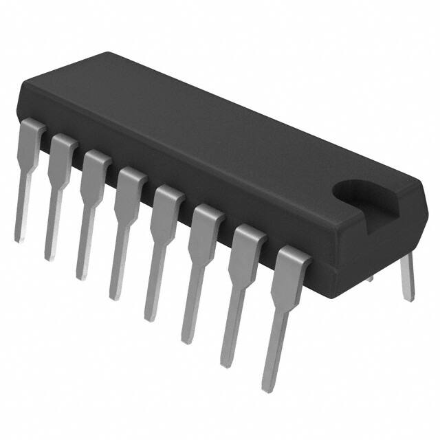
NCV7601
Quad Driver
This automotive grade product provides a versatile interface
between control logic and many types of loads. The inputs accept a
wide range of control signal levels while the open-collector outputs
feature independent thermal and current limiting. Integral transient
suppression diodes are provided at all inputs and outputs.
http://onsemi.com
Features
•�Operation in -40°C - 125°C Environment
•�TTL/DTL/CMOS Compatible Inputs
•�NAND Logic with Common Enable
•�VCEX ≥ 60 V, VCE(SUS) ≥ 40 V
•�VCE(SAT) ≤ 650 mV @ IC = 600 mA
•�Thermally Efficient Fused-Lead Package
•�Pin Compatible with:
-�CA3242/CA3262
-�UDx2543/UDx2549/UDx2559
-�L6220/L6221/L9222
•�AEC Qualified
•�PPAP Capable
•�Pb-Free Package is Available*
1
PDIP-16
P SUFFIX
CASE 648
MARKING DIAGRAM
16
Typical Applications
NCV7601P
AWLYYWWG
•�Body and Drivetrain Electronics
•�Incandescent Lamp/LED Loads
•�Solenoid/Relay/Inductor Loads
•�Heater/Resistor Loads
•�Stepper/DC Motor Loads
1
A
WL
YY
WW
G
ABSOLUTE MAXIMUM RATINGS
Rating
Value
Unit
VCC
-0.3 to 7.0
V
Logic Input Voltage (INA, INB, INC, IND, ENABLE)
-0.3 to 15
V
Power Output (OUTA, OUTB, OUTC, OUTD)
-0.3 to 60
V
Junction Temperature Range, TJ
-40 to 150
°C
Storage Temperature Range
-55 to 150
°C
ESD Susceptibility (Human Body Model)
2.0
kV
Package Thermal Resistance
Junction-to-Case, RqJC
Junction-to-Ambient, RqJA
15
50
°C/W
°C/W
260 peak
°C
Lead Temperature Soldering: Wave Solder (through
hole styles only) (Note 1)
Stresses exceeding Maximum Ratings may damage the device. Maximum
Ratings are stress ratings only. Functional operation above the Recommended
Operating Conditions is not implied. Extended exposure to stresses above the
Recommended Operating Conditions may affect device reliability.
1. 10 second maximum.
*For additional information on our Pb-Free strategy and soldering details, please
download the ON Semiconductor Soldering and Mounting Techniques
Reference Manual, SOLDERRM/D.
©� Semiconductor Components Industries, LLC, 2007
October, 2007 - Rev. 5
1
= Assembly Location
= Wafer Lot
= Year
= Work Week
= Pb-Free Package
PIN CONNECTIONS
1
16
OUTA
INA
CLAMPAB
OUTB
INB
ENABLE
GND
GND
GND
GND
OUTC
CLAMPCD
VCC
INC
OUTD
IND
ORDERING INFORMATION
Device
NCV7601P
NCV7601PG
Package
Shipping
PDIP-16
25 Units/Rail
PDIP-16
(Pb-Free)
25 Units/Rail
Publication Order Number:
NCV7601/D
�NCV7601
+14 V
NCV7601
1
16
A
2
15
Heater
B
3
ENA
4
13
5
12
VCC
Solenoid or Relay
14
6
Controller
+5.0 V
11
C
30 V
10
7
194 Lamp
D
9
8
Figure 1. Typical Driver Applications
ELECTRICAL CHARACTERISTICS (4.0 V ≤ VCC ≤ 5.5 V, -40°C ≤ TJ ≤ 125°C, unless otherwise specified.) Note 2
Characteristic
Test Conditions
Min
Typ
Max
Unit
Outputs Off, VCC = 5.5 V
Note 3 IOUT = 600 mA, VCC = VIN = 5.5 V
(four outputs on)
(one output on)
-
-
5.0
mA
-
-
65
20
mA
mA
IOUT = 600 mA, VIN = 2.0 V, VCC = 4.0 V
-
-
650
mV
VOUT = 60 V, VIN = 0.8 V, VCC = 5.5 V
-
-
50
mA
4.5 V < VOUT < 16 V, VCC = 5.0 V
-
-
1.8
A
-
150
180
210
°C
VCC = 5.5 V
40
-
-
V
Forward Voltage
IF = 1.5 A, VCC = 5.5 V
-
-
2.0
V
Leakage Current
VR = 60 V, VCC = 5.5 V
-
-
100
mA
Input Current
0 V ≤ VIN ≤ VCC
-2.0
-
10
mA
Input High Voltage
IOUT = 600 mA
2.0
-
-
V
Input Low Voltage
IOUT = 600 mA
-
-
0.8
V
IOUT = 500 mA
-
-
10
ms
GENERAL
VCC Supply Current
OUTPUT DRIVERS
Saturation Voltage
Leakage Current
Current Limit
Thermal Shutdown
Sustaining Voltage, VCE(SUS)
CLAMP DIODES
INPUT
AC CHARACTERISTICS (Note 4)
Turn-On Delay, Turn-Off Delay
2. Designed to meet these characteristics over the stated temperature range, though may not be 100% parametrically tested in production.
3. Pulse test.
4. Input rise time ≤ 10 ns, falltime ≤ 10 ns, measured at 50% points.
http://onsemi.com
2
�NCV7601
PACKAGE PIN DESCRIPTION
PACKAGE PIN #
PIN SYMBOL
FUNCTION
1
OUTA
2
CLAMPAB
3
OUTB
Driver B Output
4
GND
Ground
5
GND
Ground
Driver A Output
Diode Clamp to Driver A and Driver B
6
OUTC
7
CLAMPCD
Driver C Output
8
OUTD
9
IND
Driver D Input
10
INC
Driver C Input
11
VCC
5.0 V Input Supply Voltage
12
GND
Ground
13
GND
Ground
14
ENABLE
15
INB
Driver B Input
16
INA
Driver A Input
Diode Clamp to Driver C and Driver D
Driver D Output
ENABLE Input to all Drivers
VCC
OUTX = INX • ENA
Thermal Limit
+
-
CLAMP
DT
J
OUTx
Predriver
INx
Current Limit
ENABLE
+
18 V
18 V
V
1.35 V
-
Figure 2. Simplified Block Diagram - Each Driver
http://onsemi.com
3
D
I
很抱歉,暂时无法提供与“NCV7601P”相匹配的价格&库存,您可以联系我们找货
免费人工找货