ON Semiconductor
Is Now
To learn more about onsemi™, please visit our website at
www.onsemi.com
onsemi and and other names, marks, and brands are registered and/or common law trademarks of Semiconductor Components Industries, LLC dba “onsemi” or its affiliates and/or
subsidiaries in the United States and/or other countries. onsemi owns the rights to a number of patents, trademarks, copyrights, trade secrets, and other intellectual property. A listing of onsemi
product/patent coverage may be accessed at www.onsemi.com/site/pdf/Patent-Marking.pdf. onsemi reserves the right to make changes at any time to any products or information herein, without
notice. The information herein is provided “as-is” and onsemi makes no warranty, representation or guarantee regarding the accuracy of the information, product features, availability, functionality,
or suitability of its products for any particular purpose, nor does onsemi assume any liability arising out of the application or use of any product or circuit, and specifically disclaims any and all
liability, including without limitation special, consequential or incidental damages. Buyer is responsible for its products and applications using onsemi products, including compliance with all laws,
regulations and safety requirements or standards, regardless of any support or applications information provided by onsemi. “Typical” parameters which may be provided in onsemi data sheets and/
or specifications can and do vary in different applications and actual performance may vary over time. All operating parameters, including “Typicals” must be validated for each customer application
by customer’s technical experts. onsemi does not convey any license under any of its intellectual property rights nor the rights of others. onsemi products are not designed, intended, or authorized
for use as a critical component in life support systems or any FDA Class 3 medical devices or medical devices with a same or similar classification in a foreign jurisdiction or any devices intended for
implantation in the human body. Should Buyer purchase or use onsemi products for any such unintended or unauthorized application, Buyer shall indemnify and hold onsemi and its officers, employees,
subsidiaries, affiliates, and distributors harmless against all claims, costs, damages, and expenses, and reasonable attorney fees arising out of, directly or indirectly, any claim of personal injury or death
associated with such unintended or unauthorized use, even if such claim alleges that onsemi was negligent regarding the design or manufacture of the part. onsemi is an Equal Opportunity/Affirmative
Action Employer. This literature is subject to all applicable copyright laws and is not for resale in any manner. Other names and brands may be claimed as the property of others.
�NCV7702B
1 A Dual H-Bridge Driver
This dual full-bridge driver IC is intended for 14 V automotive
stepper and DC motor applications. Its four half-bridge outputs are
configured as two channels and are programmed by six TTL
compatible inputs, allowing flexible control of bridge operation. The
device operates in standby mode, run mode, or brake mode and
typically consumes less than 1 mA while in standby. In run mode,
each half-bridge output can deliver load current in either direction.
Brake mode activates the low side transistors or high side transistors
at the selected outputs. On-chip recirculation diodes are provided,
and the IC has multiple fault protection modes. Overcurrent
detection protects against shorted loads between outputs and shorts
to supply or ground at each output. An overcurrent fault condition
activates an internal timer, which modulates faulted outputs at low
duty cycle. An overcurrent condition in one channel does not affect
operation in the other. Overvoltage and overtemperature detection
are also provided, and turn off all bridge outputs during these fault
conditions. Recovery from all fault conditions is automatic; the IC
will resume normal operation in its previously selected mode upon
fault resolution. Diagnostic ability is provided by two open-collector
STATUS outputs which report the fault status of each channel
independently during overcurrent faults, and together during
overvoltage or overtemperature faults.
Features
http://onsemi.com
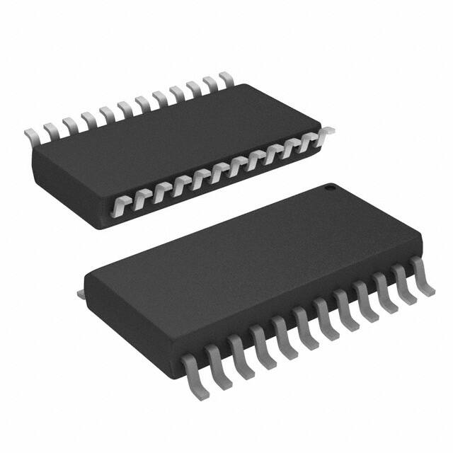
SO-24L
DW SUFFIX
CASE 751E
24
1
MARKING DIAGRAM
24
NCV7702B
AWLYYWWG
1
A
WL
YY
WW
G
•�Single 7 V-16 V Supply
•�Low Standby Current:
= Assembly Location
= Wafer Lot
= Year
= Work Week
= Pb-Free Device
PIN CONNECTIONS
1.0 mA Typically
•�3.3 V / 5 V Compatible Inputs
•�Independent Channel Enable
•�Channels Configurable as:
♦�Full-Bridge Drive
♦�Half-Bridge, High Side or Low Side Drive
•�On-Chip Recirculation Diodes
•�Fault Protection with Automatic Recovery for:
♦�Overcurrent
♦�Overvoltage
♦�Overtemperature
•�Fault Diagnostic STATUS Outputs
•�Internally Fused Leads in SO–24L Package
•�AEC Qualified
•�PPAP Capable
•�These are Pb-Free Devices*
♦�<
VB1
OUT1B
OUT1A
STATUS1
PGND
PGND
PGND
PGND
IN1A
IN1B
AGND
EN1
1
24
VB2
OUT2B
OUT2A
STATUS2
PGND
PGND
PGND
PGND
IN2A
IN2B
CT
EN2
ORDERING INFORMATION
Device
Applications
•�Automotive and Industrial Driver for:
Package
Shipping†
NCV7702BDWG
SO-24L
(Pb-Free)
31 Units/Rail
NCV7702BDWR2G
SO-24L 1000 Tape & Reel
(Pb-Free)
†For information on tape and reel specifications,
including part orientation and tape sizes, please
refer to our Tape and Reel Packaging Specifications
Brochure, BRD8011/D.
♦�DC
or Stepper Motors
♦�Relays or Solenoids
♦�Unipolar or Bipolar Loads
*For additional information on our Pb-Free strategy and soldering details, please download the ON Semiconductor Soldering and Mounting
Techniques Reference Manual, SOLDERRM/D.
©� Semiconductor Components Industries, LLC, 2007
October, 2007 - Rev. 1
1
Publication Order Number:
NCV7702B/D
�NCV7702B
OUT1A
VB1
OUT1B
OUT2A
Overvolt.
Bandgap
Regulator
VB2
OUT2B
STATUS2
Overtemp.
VBG
OV
OT
OC
Half-Bridge Control
Half-Bridge Control
OC
Overcurrent
Duty Cycle
OC
Half-Bridge Control
VBG
Half-Bridge Control
STATUS1
OC
OV
OT
OV
OT
PGND PGND PGND PGND EN1 IN1A IN1B
CT
AGND
IN2B IN2A EN2 PGND PGND PGND PGND
Figure 1. Block Diagram
MAXIMUM RATINGS
Rating
Value
Unit
-0.5 to 30
V
60
V
-0.3 to 7.0
V
150
°C
Storage Temperature Range
-65 to 150
°C
Package Thermal Resistance:
Junction-to-Case, RqJC
Junction-to-Ambient, RqJA
9
55
°C/W
°C/W
2.0
200
kV
V
260 peak
°C
3
-
Power Supply Voltage, VB
Peak Transient Voltage (46 V Load Dump @ VB = 14 V)
Logic Inputs & Status Outputs
Junction Temperature, TJ
ESD Capability
Human Body Model
Machine Model
Peak Reflow Soldering Temperature (60 to 150 seconds at 217°C) (Note 1)
Moisture Sensitivity Level (MSL)
Stresses exceeding Maximum Ratings may damage the device. Maximum Ratings are stress ratings only. Functional operation above the
Recommended Operating Conditions is not implied. Extended exposure to stresses above the Recommended Operating Conditions may affect
device reliability.
1. For additional information on our Pb-Free strategy and soldering details, please download the ON Semiconductor Soldering and Mounting
Techniques Reference Manual, SOLDERRM/D.
http://onsemi.com
2
�NCV7702B
ELECTRICAL CHARACTERISTICS (7.0 V v VB v 16 V, -40°C v TJ v 125°C; unless otherwise specified.) Notes 2 and 3.
Test Conditions
Characteristic
Min
Typ
Max
Unit
-
1.0
-
10
40
mA
mA
General Characteristics
Quiescent Current
Standby Mode, VB ≤ 12.8 V
Run Mode, IOUT = 750 mA, Both Channels
Logic Inputs
High Level Input Voltage, VIH
-
2.0
-
-
V
Low Level Input Voltage, VIL
-
-
-
0.8
V
INX Input Current
VIN = 5.0 V
VIN = 0 V
-5.0
0
0
5.0
-
mA
mA
ENX Input Current
VIN = 5.0 V
VIN = 0 V
-5.0
130
0
200
5.0
mA
mA
ENX Delay, tPE
50% of ENX to 50% of OUTX; Note 4 Turn ON
Turn Off
-
-
25
60
ms
Saturation Voltage, VSL
ISTATUS = 4.0 mA
-
-
0.4
V
Leakage Current
VSTATUS = 5.0 V
-
-
10
mA
Total Output Saturation Voltage
IOUT = 750 mA, Each Channel
-
2.5
3.0
V
Output Saturation Voltage High
IOUT = 750 mA, VB - VOUT, Each Driver
-
1.25
1.6
V
Output Saturation Voltage Low
IOUT = 750 mA, VOUT - VPGND, Each Driver
-
1.25
1.6
V
Output Leakage
VOUT = VB
VOUT = VPGND
-5.0
0
0
5.0
-
mA
mA
Overcurrent Threshold, IOC
Low Side, Each Channel
High Side, Each Channel
0.9
0.775
1.25
0.900
1.6
1.10
A
Overcurrent Duty Cycle
470 pF ≤ CT ≤ 1500 pF; Note 5
3.0
4.0
6.0
%
Switching Delay, tPI
Sink to Source
Source to Sink
50% of INX to 60% of OUTX; Note 6
50% of INX to 40% of OUTX; Note 6
0.20
0.20
-
14
10
Dead Band Time, tDB
Note 6
0.10
-
10
ms
Recirculation Diode Forward Voltage
IDIODE = 750 mA
-
-
2.5
V
Status Outputs
Half-Bridge Driver Outputs
ms
Delay Timer
Charge Current, ICHG
-
-85
-65
-45
mA
Discharge Current, IDCH
-
1.25
2.0
3.25
mA
Input Threshold High, VCH
-
1.85
2.0
2.15
V
Input Threshold Low, VDC
-
200
300
400
mV
Global Fault Protection
Overtemperature Detection Threshold
Note 7
150
-
210
°C
Overtemperature Hysteresis
Note 7
-
15
-
°C
Overvoltage Detection Threshold
Note 8
Overvoltage Hysteresis
-
26
28
30
V
500
850
1200
mV
2. Designed to meet these characteristics over the stated voltage and temperature recommended operating ranges, though may not be 100%
parametrically tested in production.
3. Operation is guaranteed down to VB = 6.0 V. Electrical characteristics may be outside the limits at that voltage.
4. See Figures 2 and 3; VB = 14 V, R = 100 W.
5. CT must remain in this range to guarantee proper operation, and to ensure part integrity, during hard short conditions.
6. See Figures 2 and 4; VB = 14 V, R = 100 W.
7. Guaranteed by design.
8. Consult factory for no overvoltage detection or lower overvoltage detection threshold options.
http://onsemi.com
3
�NCV7702B
PACKAGE PIN DESCRIPTION
PACKAGE PIN #
PIN SYMBOL
FUNCTION
1
VB1
2
OUT1B
Half-bridge output controlled by IN1B.
3
OUT1A
Half-bridge output controlled by IN1A.
4
STATUS1
5
PGND
Power supply return.
6
PGND
Power supply return.
7
PGND
Power supply return.
8
PGND
Power supply return.
9
IN1A
Logic level input.
10
IN1B
Logic level input.
11
AGND
12
EN1
Enable for OUT1A and OUT1B.
13
EN2
Enable for OUT2A and OUT2B.
14
CT
15
IN2B
Logic level input.
16
IN2A
Logic level input.
17
PGND
Power supply return.
18
PGND
Power supply return.
19
PGND
Power supply return.
20
PGND
Power supply return.
21
STATUS2
22
OUT2A
Half-bridge output controlled by IN2A.
23
OUT2B
Half-bridge output controlled by IN2B.
24
VB2
Power supply input voltage; overvoltage detection occurs at this pin.
Diagnostic output; reports channel #1 fault condition.
Analog supply return; reference for external CT capacitor, device substrate.
External capacitor; sets overcurrent delay time and duty cycle.
Diagnostic output; reports channel #2 fault condition.
Power supply input voltage.
http://onsemi.com
4
�NCV7702B
INPUT LOGIC TABLE
EN1 = EN2 = 0 = Standby Mode
Channel #1
Channel #2
EN1
IN1A
IN1B
OUT1A
OUT1B
Mode
EN2
IN2A
IN2B
OUT2A
OUT2B
Mode
1
0
0
Low
Low
Brake Low
1
0
0
Low
Low
Brake Low
1
0
1
Low
High
Run
1
0
1
Low
High
Run
1
1
0
High
Low
Run
1
1
0
High
Low
Run
1
1
1
High
High
Brake High
1
1
1
High
High
Brake High
0
X
X
|Z|
|Z|
Off
0
X
X
|Z|
|Z|
Off
NOTE:
X = Don't Care; |Z| = Output Off.
STATUS OUTPUT TABLE
STATUS1
STATUS2
Fault Diagnostic
1
1
No Fault.
0
1
Channel 1 Overcurrent; Note 9
1
0
Channel 2 Overcurrent; Note 9
0
0
Overvoltage, Overtemperature or Overcurrent in Both Channels; Notes 9 and 10
9. During overcurrent, the STATUS outputs will be modulated at the overcurrent duty cycle rate. See Figure 5.
10. During overtemperature, the STATUS outputs will be modulated by the thermal time constants.
+14 V
1
24
VB2
VB1
R
OUTX
R
OUT1B
OUT2B
OUT1A
OUT2A
STATUS2
STATUS1
PGND
PGND
PGND
PGND
NCV7702B
PGND
PGND
PGND
PGND
INX
IN1A
IN2A
IN1B
IN2B
CT
AGND
12
ENX
13
EN2
EN1
Figure 2. Propagation Delay and Dead Band Timing Test Circuit
http://onsemi.com
5
�NCV7702B
VIH
ENX
VIL
tPE
ON
OUTX
OFF
T
Figure 3. ENX Propagation Delay
VIH
INX
VIL
tPI
tPI
VSRC
OUTX
60%
½VB
40%
VSNK
tDB
tDB
T
Figure 4. OUTX Propagation Delay and Dead Band Timing
STATUSX
VSH
VSL
IOC
ION
OUTX
OFF
CT
VCH
tON
tOFF
VDC
0
T
Figure 5. Overcurrent, Status and Duty Cycle Timing
http://onsemi.com
6
�NCV7702B
Functional Description
The NCV7702B is arranged as four half-bridge drivers in
two independent channels. Each channel can be operated as
a full-bridge or half-bridge to drive multiple load
configurations. Separate ENable inputs are used to control
which channel is active. Each ENable input has a nominal
50 kW internal pull-down resistor to ensure that the outputs
remain off during power-up. The four INX control inputs
address each half-bridge output, and each output follows the
state of its input. When INX is at logic one, OUTX is sourcing
current from the VB supply; when INX is at logic zero,
OUTX is sinking current to the PGND return.
current IDCH. Upon detection of overcurrent, charging
current ICHG is switched on and the CT capacitor begins
charging from zero towards the timer's upper threshold
(VDH.) When the capacitor voltage crosses VDH the faulted
channel's outputs are switched off and the channel's
STATUS output is switched from VSH to VSL (see Figure 5.)
The charging current is switched off, and the capacitor
voltage decreases toward the timer's lower (VDL) threshold.
Upon crossing the lower threshold, the channel's outputs are
switched on and the channel's STATUS output returns to its
VSH voltage. This behavior continues until the fault
condition is resolved. If the fault condition is resolved
before VDH is reached, the timer is reset and no modulation
of the previously faulted channel's half-bridge or STATUS
outputs occurs.
After the timer's initial charge cycle, the output off time
is:
tOFF = CT (VCH - VDc)/ IDCH.
The output on time is: tON = CT (VCH - VDc)/ ICHG.
The timer period is:
T = tOFF + tON.
The value of the CT capacitor is required to be in the range
of 470 to 1500 pF. Values below 470 pF may cause timer
mis-operation due to internal delays, while values above
1500 pF may cause excessive power dissipation.
Connecting the CT pin to ground will prevent operation of
the current limit function.
Half-Bridge Drivers
The half-bridge drivers of each OUTX are comprised of
an NPN Darlington driver on the low-side and a compound
PNP-NPN driver on the high-side. Each half-bridge driver
is capable of 1 A (min) peak current and is overcurrent
protected against load and system faults. Cross conduction
currents within each half-bridge are suppressed by the use
of a dead-band timer. Each INX input contains an
independent dead-band timer that is activated on either
edge of the input transition.
Overcurrent detection circuitry is provided in both the
low-side and high-side drivers of each half-bridge output.
When activated, the overcurrent detectors trigger an internal
timer which causes both half-bridge drivers in the same
channel to be modulated at 4% (Typ.) duty cycle. The timer
also activates the channel's STATUS output, causing it to be
similarly modulated (see Figure 5.) Upon removal of the
fault condition, the channel automatically resumes
operation in its previously programmed mode and its
STATUS output returns to a no-fault state.
Recirculation diodes at each OUTX clamp load transients
to either VB or PGND and help contain switching currents
within each load loop.
Overvoltage and Overtemperature Protection
Overvoltage detection circuitry is intended to allow
limited operation of the NCV7702B during double-battery
conditions. Detection is via the VB1 pin and causes both
channels of the IC to be switched off when the detection
threshold is exceeded. Hysteresis is provided to improve
noise immunity of the overvoltage function.
Overtemperature detection circuitry monitors the
junction temperature internal to the IC and is intended to
ensure reliability by preventing excessive power
dissipation. The detection circuitry is centrally located on
the IC and causes both channels of the IC to be switched off
when the detection threshold is exceeded. Hysteresis is
provided to improve noise immunity of the overtemperature
function.
Both STATUS outputs are switched to the VSL state
during either overvoltage or overtemperature faults. Normal
operation of the IC is resumed automatically upon resolution
the fault, and the STATUS outputs return to the VSH State.
Overcurrent Duty Cycle Timer
A single timer for overcurrent duty cycle is common to
both channels. The timer is triggered when a half-bridge in
either channel has detected an overcurrent fault. An external
capacitor connected to the NCV7702B's CT pin is used to
program the period of the timer, and the ratio of two
internally fixed currents programs the timer's duty cycle.
The capacitor voltage is normally kept at zero by discharge
http://onsemi.com
7
�NCV7702B
33
2.54
31
2.52
29
2.50
25
VSAT (V)
IVB (mA)
27
VB = 7 V
23
21
VB = 16 V
2.46
2.44
VB = 16 V
19
2.48
VB = 7 V
2.42
17
15
-50
0
50
100
2.40
-50
150
0
TEMPERATURE (°C)
Figure 6. Run Mode Bias Current vs. Temperature
50
TEMPERATURE (°C)
100
150
Figure 7. Total VSAT vs. Temperature
MBR2040LT3
1000 mF
50 V
47 nF
+
1
24
VB2
VB1
22 nF
OUT1B
OUT2B
OUT1A
OUT2A
STATUS1
PGND
STATUS2
PGND
VIGN
PGND
PGND
NCV7702B
PGND
PGND
PGND
NCV8501
VOUT
VIN
+
VBAT
7 V - 16 V
PGND
RESET ENABLE
IN1A
IN2A
IN1B
IN2B
AGND
CT
12
FLAG
DELAY
MON
GND
13
EN1
EN2
CT
1.0 nF
Microcontroller
VDD
RST
I/O
+
Figure 8. Application Diagram
NOTE:
Both VB inputs must be connected to the power supply. All PGND pins must be connected to the power supply return (GND).
For best thermal performance, the PGND pins should be connected to a thermal plane (heat sink) on the PC board.
http://onsemi.com
8
�NCV7702B
PACKAGE DIMENSIONS
SO-24L
DW SUFFIX
CASE 751E-04
ISSUE E
-A24
NOTES:
1. DIMENSIONING AND TOLERANCING PER ANSI
Y14.5M, 1982.
2. CONTROLLING DIMENSION: MILLIMETER.
3. DIMENSIONS A AND B DO NOT INCLUDE
MOLD PROTRUSION.
4. MAXIMUM MOLD PROTRUSION 0.15 (0.006)
PER SIDE.
5. DIMENSION D DOES NOT INCLUDE DAMBAR
PROTRUSION. ALLOWABLE DAMBAR
PROTRUSION SHALL BE 0.13 (0.005) TOTAL IN
EXCESS OF D DIMENSION AT MAXIMUM
MATERIAL CONDITION.
13
-B-
12X
P
0.010 (0.25)
1
M
B
M
12
24X
D
J
0.010 (0.25)
M
T A
S
B
S
F
R
X 45 _
C
-TSEATING
PLANE
M
22X
G
K
DIM
A
B
C
D
F
G
J
K
M
P
R
MILLIMETERS
MIN
MAX
15.25
15.54
7.40
7.60
2.35
2.65
0.35
0.49
0.41
0.90
1.27 BSC
0.23
0.32
0.13
0.29
0_
8_
10.05
10.55
0.25
0.75
INCHES
MIN
MAX
0.601
0.612
0.292
0.299
0.093
0.104
0.014
0.019
0.016
0.035
0.050 BSC
0.009
0.013
0.005
0.011
0_
8_
0.395
0.415
0.010
0.029
ON Semiconductor and
are registered trademarks of Semiconductor Components Industries, LLC (SCILLC). SCILLC reserves the right to make changes without further notice
to any products herein. SCILLC makes no warranty, representation or guarantee regarding the suitability of its products for any particular purpose, nor does SCILLC assume any liability
arising out of the application or use of any product or circuit, and specifically disclaims any and all liability, including without limitation special, consequential or incidental damages.
“Typical” parameters which may be provided in SCILLC data sheets and/or specifications can and do vary in different applications and actual performance may vary over time. All
operating parameters, including “Typicals” must be validated for each customer application by customer's technical experts. SCILLC does not convey any license under its patent rights
nor the rights of others. SCILLC products are not designed, intended, or authorized for use as components in systems intended for surgical implant into the body, or other applications
intended to support or sustain life, or for any other application in which the failure of the SCILLC product could create a situation where personal injury or death may occur. Should
Buyer purchase or use SCILLC products for any such unintended or unauthorized application, Buyer shall indemnify and hold SCILLC and its officers, employees, subsidiaries, affiliates,
and distributors harmless against all claims, costs, damages, and expenses, and reasonable attorney fees arising out of, directly or indirectly, any claim of personal injury or death
associated with such unintended or unauthorized use, even if such claim alleges that SCILLC was negligent regarding the design or manufacture of the part. SCILLC is an Equal
Opportunity/Affirmative Action Employer. This literature is subject to all applicable copyright laws and is not for resale in any manner.
PUBLICATION ORDERING INFORMATION
LITERATURE FULFILLMENT:
Literature Distribution Center for ON Semiconductor
P.O. Box 5163, Denver, Colorado 80217 USA
Phone: 303-675-2175 or 800-344-3860 Toll Free USA/Canada
Fax: 303-675-2176 or 800-344-3867 Toll Free USA/Canada
Email: orderlit@onsemi.com
N. American Technical Support: 800-282-9855 Toll Free
USA/Canada
Europe, Middle East and Africa Technical Support:
Phone: 421 33 790 2910
Japan Customer Focus Center
Phone: 81-3-5773-3850
http://onsemi.com
9
ON Semiconductor Website: www.onsemi.com
Order Literature: http://www.onsemi.com/orderlit
For additional information, please contact your local
Sales Representative
NCV7702B/D
�