NSVR201MX
Schottky Barrier Diode
for Mixer and Detector
Automotive Schottky Barrier Diode designed for compact and
efficient designs. AEC−Q101 qualified Schottky Barrier Diode and
PPAP capable suitable for automotive applications.
www.onsemi.com
Features
•
•
•
•
•
•
Small Interterminal Capacitance
Less Parasitic Components
Small Forward Voltage
Small−sized Package
Pb−Free, Halogen Free and RoHS Compliant
AEC−Q101 Qualified and PPAP Capable
2 V, 50 mA
C = 0.15 pF typ.
Schottky Barrier Diode
Typical Applications
• Microwave and Submilliwave Mixer
• Microwave and Submilliwave Detector
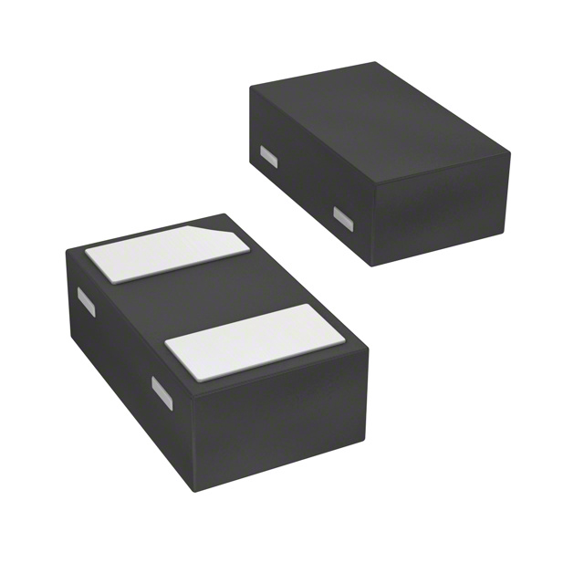
X2DFN2 1.0 x 0.6, 0.65P
CASE 714AB
Specifications
Table 1. ABSOLUTE MAXIMUM RATINGS at TA = 25°C
ELECTRICAL CONNECTION
Symbol
Value
Unit
Reverse Voltage
VR
2
V
Forward Current
IF
50
mA
TJ, Tstg
−55 to +150
°C
Parameter
Operating Junction
and Storage Temperature
1
Cathode
Anode
MARKING DIAGRAM
Stresses exceeding those listed in the Maximum Ratings table may damage the
device. If any of these limits are exceeded, device functionality should not be
assumed, damage may occur and reliability may be affected.
RF M
RF
M
= Specific Device Code
= Date Code
ORDERING INFORMATION
See detailed ordering and shipping information on page 2 of
this data sheet.
© Semiconductor Components Industries, LLC, 2016
January, 2019 − Rev. 2
1
Publication Order Number:
NSVR201MX/D
�NSVR201MX
Table 2. ORDERING INFORMATION
Device
Marking
Package
Shipping†
NSVR201MXT5G
RF
X2DFN2 1.0 x 0.65 P
(Pb−Free / Halogen Free)
8,000 / Tape & Real
†For information on tape and reel specifications, including part orientation and tape sizes, please refer to our Tape and Reel Packaging
Specification Brochure, BRD8011/D.
Table 3. ELECTRICAL CHARACTERISTICS at TA = 25°C (Notes 1, 2)
Value
Parameter
Symbol
Conditions
Min
Reverse Voltage
VR
IR = 10 μA
2
Forward Voltage
VF
IF = 1 mA
Series Resistance
RS
IF = 10 mA
Interterminal Capacitance
C
VR = 0 V, f = 1 MHz
Typ
Max
Units
320
mV
14
18
Ω
0.15
0.20
pF
V
1. Product parametric performance is indicated in the Electrical Characteristics for the listed test conditions, unless otherwise noted. Product
performance may not be indicated by the Electrical Characteristics if operated under different conditions.
2. Pay attention to handling since it is liable to be affected by static electricity due to the high−frequency process adopted.
www.onsemi.com
2
�IF − VF
10
7
5
3
2
TAA = 25°C
1.0
7
5
3
2
0.1
7
5
3
2
0.01
7
5
3
2
0.1
0.2
0.3
0.4
Forward Voltage, VF − V
0.4
0.3
1 mA
0.2
100 μA
0
−100
−50
0
50
100
Ambient Temperature, TA − °C
IT18041
150
200
IT18042
IR − TA
100
TA = 25°C
Reverce Current, IR − μA
Reverce Current, IR − μA
10 mA
0.5
IR − VR
10
7
5
3
2
1.0
7
5
3
2
0.1
7
5
3
2
10
1.0
0.1
0.01
0.001
0
0.5
1.0
1.5
2.0
Reverce Voltage, VR − V
0.0001
−100
2.5
5
100
150
200
IT18044
0.50
Series inductance, Ls − nH
3
2
0.1
7
5
3
2
0.40
0.30
0.20
1.5
Reverce Voltage, VR − V
TA = 25°C
f = 100 MHz
0.10
0.00
0.01
1.0
50
0.60
TA = 25°C
f = 1 MHz
0.5
0
Ambient Temperature, TA − °C
Ls − IF
7
0
−50
IT18043
C − VR
1.0
Interterminal Capacitance, C − pF
0.5
0.1
0.001 0
0.01
7
5
3
2
0.001
VF − TA
0.6
Forward Voltage, VF − V
Forward Current, IF − mA
NSVR201MX
2.0
0
10
20
30
40
Forward Current, IF − mA
IT18045
Figure 1.
www.onsemi.com
3
50
60
�NSVR201MX
Table 4. S PARAMETER (ZO = 50 Ω)
I = 0 mA
I = 0.02 mA
I = 0.05 mA
I = 0.1 mA
I = 0.2 mA
I = 0.5 mA
Freq
[GHz]
MAG
ANG
MAG
ANG
MAG
ANG
MAG
ANG
MAG
ANG
MAG
ANG
1
0.964
−4.4
0.988
−4.3
0.978
−4.3
0.963
−4.3
0.933
−4.4
0.845
−4.3
2
0.967
−9.7
0.990
−9.6
0.981
−9.6
0.966
−9.7
0.937
−9.7
0.852
−9.5
3
0.957
−15.2
0.981
−15.1
0.971
−15.2
0.956
−15.2
0.925
−15.4
0.838
−15.7
4
0.956
−20.5
0.980
−20.3
0.970
−20.5
0.956
−20.5
0.925
−20.6
0.840
−20.4
5
0.961
−26.0
0.986
−25.7
0.977
−25.9
0.960
−26.0
0.929
−26.2
0.838
−26.3
6
0.954
−32.3
0.981
−31.9
0.970
−32.1
0.953
−32.3
0.919
−32.5
0.822
−32.5
7
0.943
−39.2
0.969
−38.7
0.959
−39.0
0.942
−39.2
0.909
−39.6
0.814
−40.4
8
0.943
−45.7
0.967
−45.2
0.958
−45.4
0.942
−45.7
0.911
−46.2
0.823
−47.4
9
0.947
−52.8
0.975
−52.2
0.963
−52.5
0.946
−52.8
0.910
−53.3
0.809
−54.2
10
0.940
−60.6
0.968
−59.9
0.957
−60.2
0.938
−60.6
0.902
−61.2
0.799
−62.6
11
0.921
−69.7
0.950
−68.9
0.939
−69.3
0.919
−69.7
0.883
−70.4
0.777
−72.0
12
0.895
−80.4
0.928
−79.4
0.914
−79.9
0.893
−80.4
0.852
−81.2
0.738
−83.5
13
0.882
−88.8
0.912
−87.7
0.900
−88.2
0.881
−88.8
0.843
−89.6
0.735
267.9
14
0.872
261.9
0.906
263.1
0.893
262.4
0.871
261.9
0.831
261.0
0.715
258.8
15
0.870
252.7
0.900
253.9
0.887
253.2
0.868
252.6
0.830
251.6
0.723
249.0
16
0.874
242.8
0.903
244.1
0.891
243.4
0.873
242.7
0.838
241.6
0.733
238.1
17
0.874
231.6
0.907
233.1
0.894
232.3
0.873
231.6
0.833
230.4
0.720
227.0
18
0.877
220.8
0.911
222.5
0.898
221.6
0.875
220.7
0.833
219.3
0.715
215.4
19
0.860
210.3
0.895
212.1
0.881
211.1
0.859
210.2
0.817
208.7
0.700
204.2
20
0.847
198.7
0.880
200.7
0.866
199.6
0.845
198.7
0.806
197.2
0.692
192.7
21
0.841
185.5
0.875
187.4
0.860
186.4
0.840
185.4
0.800
184.0
0.687
179.7
22
0.847
171.1
0.883
173.3
0.868
172.2
0.846
171.1
0.803
169.3
0.683
164.0
23
0.845
157.2
0.877
159.6
0.864
158.3
0.843
157.1
0.804
155.1
0.696
149.5
24
0.822
142.0
0.854
144.5
0.840
143.2
0.821
142.1
0.782
140.1
0.680
134.7
25
0.823
130.3
0.852
132.6
0.840
131.4
0.822
130.3
0.788
128.6
0.695
123.3
26
0.833
118.3
0.863
120.7
0.850
119.5
0.832
118.2
0.797
116.5
0.703
111.1
50
25
I = 0.02 mA
25 GHz
0.05 mA
0.1 mA
0.2 mA
0.5 mA
100
250
10
0
10
25
50
100
250
1 GHz
20 GHz
−250
5 GHz
−10
−25
−100
10 GHz
15 GHz
−50
Figure 2.
www.onsemi.com
4
IT18046
�MECHANICAL CASE OUTLINE
PACKAGE DIMENSIONS
X2DFN2 1.0x0.6, 0.65P
CASE 714AB
ISSUE B
DATE 21 NOV 2017
SCALE 8:1
NOTES:
1. DIMENSIONING AND TOLERANCING PER
ASME Y14.5M, 1994.
2. CONTROLLING DIMENSION: MILLIMETERS.
3. EXPOSED COPPER ALLOWED AS SHOWN.
0.10 C
A B
D
É
PIN 1
INDICATOR
E
DIM
A
A1
b
D
E
e
L
0.05 C
TOP VIEW
A
NOTE 3
0.10 C
0.10 C
A1
C
SIDE VIEW
GENERIC
MARKING DIAGRAM*
SEATING
PLANE
XX M
e
b
e/2
MILLIMETERS
MIN
NOM MAX
0.34
0.37
0.40
−−−
0.03
0.05
0.45
0.50
0.55
0.95
1.00
1.05
0.55
0.60
0.65
0.65 BSC
0.20
0.25
0.30
0.05
M
XX = Specific Device Code
M = Date Code
C A B
RECOMMENDED
SOLDER FOOTPRINT*
1
2X
L
0.05
M
C A B
BOTTOM VIEW
1.20
2X
0.47
2X
0.60
PIN 1
DIMENSIONS: MILLIMETERS
*This information is generic. Please refer to
device data sheet for actual part marking.
Pb−Free indicator, “G” or microdot “ G”,
may or may not be present. Some products
may not follow the Generic Marking.
DOCUMENT NUMBER:
DESCRIPTION:
98AON98172F
X2DFN2 1.0X0.6, 0.65P
Electronic versions are uncontrolled except when accessed directly from the Document Repository.
Printed versions are uncontrolled except when stamped “CONTROLLED COPY” in red.
PAGE 1 OF 1
ON Semiconductor and
are trademarks of Semiconductor Components Industries, LLC dba ON Semiconductor or its subsidiaries in the United States and/or other countries.
ON Semiconductor reserves the right to make changes without further notice to any products herein. ON Semiconductor makes no warranty, representation or guarantee regarding
the suitability of its products for any particular purpose, nor does ON Semiconductor assume any liability arising out of the application or use of any product or circuit, and specifically
disclaims any and all liability, including without limitation special, consequential or incidental damages. ON Semiconductor does not convey any license under its patent rights nor the
rights of others.
© Semiconductor Components Industries, LLC, 2019
www.onsemi.com
�onsemi,
, and other names, marks, and brands are registered and/or common law trademarks of Semiconductor Components Industries, LLC dba “onsemi” or its affiliates
and/or subsidiaries in the United States and/or other countries. onsemi owns the rights to a number of patents, trademarks, copyrights, trade secrets, and other intellectual property.
A listing of onsemi’s product/patent coverage may be accessed at www.onsemi.com/site/pdf/Patent−Marking.pdf. onsemi reserves the right to make changes at any time to any
products or information herein, without notice. The information herein is provided “as−is” and onsemi makes no warranty, representation or guarantee regarding the accuracy of the
information, product features, availability, functionality, or suitability of its products for any particular purpose, nor does onsemi assume any liability arising out of the application or use
of any product or circuit, and specifically disclaims any and all liability, including without limitation special, consequential or incidental damages. Buyer is responsible for its products
and applications using onsemi products, including compliance with all laws, regulations and safety requirements or standards, regardless of any support or applications information
provided by onsemi. “Typical” parameters which may be provided in onsemi data sheets and/or specifications can and do vary in different applications and actual performance may
vary over time. All operating parameters, including “Typicals” must be validated for each customer application by customer’s technical experts. onsemi does not convey any license
under any of its intellectual property rights nor the rights of others. onsemi products are not designed, intended, or authorized for use as a critical component in life support systems
or any FDA Class 3 medical devices or medical devices with a same or similar classification in a foreign jurisdiction or any devices intended for implantation in the human body. Should
Buyer purchase or use onsemi products for any such unintended or unauthorized application, Buyer shall indemnify and hold onsemi and its officers, employees, subsidiaries, affiliates,
and distributors harmless against all claims, costs, damages, and expenses, and reasonable attorney fees arising out of, directly or indirectly, any claim of personal injury or death
associated with such unintended or unauthorized use, even if such claim alleges that onsemi was negligent regarding the design or manufacture of the part. onsemi is an Equal
Opportunity/Affirmative Action Employer. This literature is subject to all applicable copyright laws and is not for resale in any manner.
PUBLICATION ORDERING INFORMATION
LITERATURE FULFILLMENT:
Email Requests to: orderlit@onsemi.com
onsemi Website: www.onsemi.com
◊
TECHNICAL SUPPORT
North American Technical Support:
Voice Mail: 1 800−282−9855 Toll Free USA/Canada
Phone: 011 421 33 790 2910
Europe, Middle East and Africa Technical Support:
Phone: 00421 33 790 2910
For additional information, please contact your local Sales Representative
�