Ordering number : ENA1346A
PCP1103
Bipolar Transistor
–30V, –1.5A, Low VCE(sat) PNP Single PCP
http://onsemi.com
Applications
•
DC / DC converters, relay drivers, lamp drivers, motor drivers, IGBT gate drivers
Features
•
•
•
Adoption of MBIT process
Low collector to emitter saturation voltage
High allowable power dissipation
•
•
•
Large current capacity
High speed switching
Halogen free compliance
Specifications
Absolute Maximum Ratings at Ta=25°C
Parameter
Symbol
Collector to Base Voltage
Conditions
Ratings
VCBO
VCEO
Collector to Emitter Voltage
Emitter to Base Voltage
VEBO
IC
ICP
Collector Current
Collector Current (Pulse)
Unit
--30
V
--30
V
--5
V
--1.5
A
--5
A
Continued on next page.
Stresses exceeding Maximum Ratings may damage the device. Maximum Ratings are stress ratings only. Functional operation above the Recommended Operating
Conditions is not implied. Extended exposure to stresses above the Recommended Operating Conditions may affect device reliability.
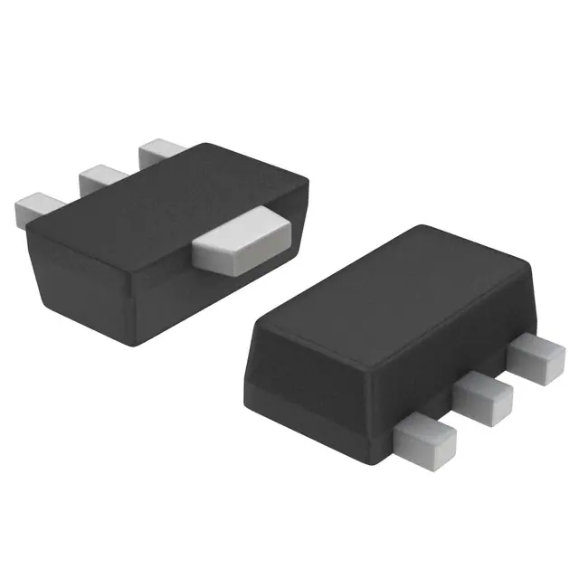
Package Dimensions
Product & Package Information
unit : mm (typ)
7007B-004
• Package
: PCP
• JEITA, JEDEC
: SC-62, SOT-89, TO-243
• Minimum Packing Quantity : 1,000 pcs./reel
Top View
PCP1103-TD-H
1.6
1
2
Marking
RF
Packing Type: TD
4.0
1.0
2.5
1.5
LOT No.
4.5
TD
3
0.4
0.4
0.5
1.5
Electrical Connection
3.0
2
1
0.75
3
1 : Base
2 : Collector
3 : Emitter
Bottom View
PCP
Semiconductor Components Industries, LLC, 2013
December, 2013
D1113 TKIM TC-00003073/N1208EA MSIM TC-00001718 No.A1346-1/5
�PCP1103
Continued from preceding page.
Parameter
Symbol
Base Current
Conditions
Ratings
IB
Unit
--300
Collector Dissipation
PC
Junction Temperature
Tj
Storage Temperature
Tstg
mA
When mounted on ceramic substrate (450mm2×0.8mm)
1.3
W
Tc=25°C
3.5
W
150
°C
--55 to +150
°C
Electrical Characteristics at Ta=25°C
Parameter
Symbol
Collector Cutoff Current
ICBO
IEBO
hFE
Emitter Cutoff Current
DC Current Gain
Gain-Bandwidth Product
Collector to Emitter Saturation Voltage
VCE= --2V, IC= --100mA
Collector to Base Breakdown Voltage
Collector to Emitter Breakdown Voltage
Turn-On Time
Storage Time
μA
μA
560
MHz
9
IC= --1mA, RBE=∞
IE= --10μA, IC=0A
pF
--250
--375
--0.85
--1.2
mV
V
--30
V
--30
V
--5
V
See specified Test Circuit.
tstg
tf
Fall Time
--0.1
--0.1
450
IC= --0.75A, IB= --15mA
IC= --10μA, IE=0A
V(BR)EBO
ton
Unit
max
200
VCB= --10V, f=1MHz
IC= --0.75A, IB= --15mA
V(BR)CBO
V(BR)CEO
Emitter to Base Breakdown Voltage
typ
VCE= --10V, IC= --300mA
VCE(sat)
VBE(sat)
Base to Emitter Saturation Voltage
min
VCB= --30V, IE=0A
VEB= --4V, IC=0A
fT
Cob
Output Capacitance
Ratings
Conditions
35
ns
115
ns
30
ns
Switching Time Test Circuit
IB1
PW=50μs
D.C.≤1%
OUTPUT
IB2
INPUT
RB
RL
50Ω
+
820μF
VCC= --12V
IC=20IB1= --20IB2= --0.75A
Ordering Information
Package
Shipping
memo
PCP
1,000pcs./reel
Pb Free and Halogem Free
IC -- VCE
Collector Current, IC -- A
--1.6
--20mA
--1.4
--1.2
--8mA
--10mA
--6mA
--4mA
--0.8
--0.6
--2mA
--0.4
VCE= --2V
--1.4
--1.2
--1.0
--0.8
--0.6
--0.4
--25°C
A
--50m
A
--40m
A
--30m
--1.8
--1.0
IC -- VBE
--1.6
Collector Current, IC -- A
--2.0
Ta=7
5°C
25°C
Device
PCP1103-TD-H
--0.2
--0.2
IB=0mA
0
0
--0.1
--0.2
--0.3
--0.4
--0.5
--0.6
--0.7
--0.8
Collector to Emitter Voltage, VCE -- V
--0.9 --1.0
IT14106
0
0
--0.2
--0.4
--0.6
--0.8
--1.0
Base to Emitter Voltage, VBE -- V
--1.2
IT14107
No.A1346-2/5
�PCP1103
hFE -- IC
7
Gain-Bandwidth Product, f T -- MHz
DC Current Gain, hFE
Ta=75°C
25°C
--25°C
2
VCE= --10V
2
5
3
f T -- IC
3
VCE= --2V
100
7
1000
7
5
3
2
100
7
5
3
5
--0.01
2
3
5
7 --0.1
2
3
5
7 --1.0
2
Collector Current, IC -- A
2
--0.01
3
3
5
7 --0.1
2
3
5
Collector Current, IC -- A
Cob -- VCB
100
2
IT14108
VCE(sat) -- IC
5
f=1MHz
IC / IB=20
7
Collector to Emitter
Saturation Voltage, VCE(sat) -- V
3
Output Capacitance, Cob -- pF
5
3
2
10
7
5
3
2
--0.1
°C
25
7
5
C
75°
Ta=
5°C
--2
3
2
--0.01
2
0.1
2
3
5 7 1.0
2
3
5 7 10
2
3
Collector to Base Voltage, VCB -- V
7
--0.01
5
2
3
5
7 --0.1
2
3
5
7 --1.0
Collector Current, IC -- A
IT01681
VCE(sat) -- IC
2
Base to Emitter
Saturation Voltage, VBE(sat) -- V
Collector to Emitter
Saturation Voltage, VCE(sat) -- V
7
5
3
2
25°
7
C
75°C
Ta=
C
--25°
5
3
2
--0.01
--0.01
2
3
5
7 --0.1
2
3
5
7 --1.0
2
Collector Current, IC -- A
μs
100
s
0μ
3
2
3
5
n
io
at
er
op
1m
s
)
°C
25
a=
(T
--0.1
7
5
Ta=25°C
Single pulse
When mounted on ceramic substrate (450mm2×0.8mm)
2 3
5 7--1.0
2 3
5 7 --10
Collector to Emitter Voltage, VCE -- V
2 3
7 --0.1
2
3
5
7 --1.0
Collector Current, IC -- A
Collector Dissipation, PC -- W
C
Collector Current, IC -- A
25°C
2
3
IT14111
PC -- Ta
When mounted on ceramic substrate
(450mm2×0.8mm)
1.4
50
D
3
2
5 7--0.1
75°C
5
很抱歉,暂时无法提供与“PCP1103-TD-H”相匹配的价格&库存,您可以联系我们找货
免费人工找货- 国内价格 香港价格
- 1+6.655681+0.86149
- 10+4.1456610+0.53660
- 100+2.66390100+0.34481
- 500+2.02407500+0.26199
- 国内价格 香港价格
- 1+6.660681+0.86213