STK5C4U3XXJGEVB
STK5C4U3xx Series
Evaluation Board
User's�Manual
www.onsemi.com
Introduction
By using this board, STK5C4U3xx series (DIPS) can be evaluated.
ONPN of EVAL Board
ONPN of IPM
Io
STK5C4U332JGEVB
STK5C4U332J−E
3A
EVAL BOARD USER’S MANUAL
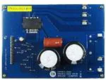
Surface
Back side
Figure 1. Evaluation Board Photos
© Semiconductor Components Industries, LLC, 2015
July, 2015 − Rev. 1
1
Publication Order Number:
EVBUM2296/D
�STK5C4U3XXJGEVB
CIRCUIT DIAGRAM
Evaluation board
+
−
2.2 �F / 630 V
470 �F / 450 V
U
+
−
38. VCC1
22 �F / 50 V
+
−
0.1 �F
V
W
+
−
+
−
2. VDD
34. VB1
32. VS1,U
28. VB2
26. VS2,V
220 �F / 35 V
VSS
−
+
1. VSS
+
STK5C4U3xxJ−E
VDD
0.1 �F
3. HIN1
HIN1
4. HIN2
HIN2
5. HIN3
HIN3
6. LIN1
LIN1
7. LIN2
LIN2
8. LIN3
LIN3
22. VB3
100
100 pF
20. VS3,W
9. FAULT
VEXT
20 k�
RF
10. ITRIP
Shunt
resistor
−
19. W-
ITRIP
11. ENABLE
ENABLE
12. RCIN
18. V-
Fault
RCIN
13. TH1
17. U-
14. TH2
TH
200 �
Figure 2. Circuit Diagram
www.onsemi.com
2
10 nF
�STK5C4U3XXJGEVB
PIN DESCRIPTION
Figure 3. Pin Description 1
Figure 4. Pin Description 2
www.onsemi.com
3
�STK5C4U3XXJGEVB
OPERATION PROCEDURE
Figure 5. Connection Example
Step 4. By inputting signal to the logic part, IPM control
is started.
(Therefore, please set electric charge to the
boot-strap capacitor of upper side to turn on lower
side IGBT before running.)
Step 1. Please connect IPM, each power supply, logic
parts, and the motor to the evaluation board, and
confirm that each power supply is OFF at this
time.
Step 2. Please impress the power supply of DC 15 V.
Step 3. Please perform a voltage setup according to
specifications, and impress the power supply
between the “+” and the “−” terminal.
NOTE: When turning off the power supply part and the
logic part, please carry out in the reverse order
to above steps.
www.onsemi.com
4
�STK5C4U3XXJGEVB
LAYOUT (TOP VIEW)
Figure 6. Layout − Surface
Figure 7. Layout − Back Side
Length: 124 mm
Side: 170 mm
Thickness: 1.6 mm
Rigid double−sided substrate (Material: FR−4)
Both sides resist coating
Copper foil thickness: 70 �m
www.onsemi.com
5
�STK5C4U3XXJGEVB
BILL OF MATERIALS
Table 1. BILL OF MATERIALS
Tolerance
Designator
Qty
Description
Value
4
Shunt resistor
27 m� /
2W
R2
1
Setting fault clear time /
resistor
R3
1
Setting time constant /
resistor
200 � /
0.1 W
±1%
SMD
1608
KOA
RK73H1JTTD2000F
Yes
R4 − R6
3
Fault, ENABLE, TH pull−up /
resistor
20 k� /
0.1 W
±1%
SMD
1608
KOA
RK73H1JTTD2002F
Yes
R7 − R12
6
Signal input low pass filter /
resistor
100 � /
0.1 W
±1%
SMD
1608
KOA
RK73H1JTTD1000F
Yes
C1, C2
2
Aluminum electrolytic
capacitor, Plus − Minus
470 �F /
450 V
±20%
Through−
hole
Rubycon
450MXC470MEFCSN35X50
Yes
C3
1
Film capacitor
Plus − Minus, Snubber
2.2 �F /
630 V
±5%
Through−
hole
PANASONIC
ECQE6225JT
Yes
C4
1
Aluminum electrolytic
capacitor, VDD − VSS
220 �F /
35 V
±20%
Through−
hole
Nippon
Chemi−Con
EKMG350ELL221MHB5D
Yes
C5 − C7, C11
4
VBx − VSx, VDD − VSS /
capacitor
0.1 �F /
50 V
±10%
SMD
1608
MURATA
GRM188B31H104K
Yes
C8 − C10
3
VBx − VSx / capacitor
22 �F /
25 V
±20%
SMD
3225
MURATA
GRM32ER71E226ME15
Yes
C13
1
Setting time constant /
capacitor
10 nF /
50 V
±10%
SMD
1608
MURATA
GRM188B11H103K
Yes
C14 − C19
6
Signal input low pass filter /
capacitor
100 pF /
50 V
±5%
SMD
1608
MURATA
GRM1882C1H101J
Yes
CN1
1
Header − 18 Pin
Through−
hole
2.54 pitch
HIROSE
ELECTRIC
A2−18PA−2.54DSA(71)
Yes
VSS, VDD,
U−, RCIN,
ITRIP, VEXT,
TH,
ENABLE,
FAULT,
HIN1−3,
LIN1−3, +, −
17
Test Pins
Through−
hole
Mac8
ST−1−3
Yes
U, V, W, +, −
5
Faston terminal (Tab)
Through−
hole
IC1
1
Inverter IPM
DIP−38
optional
Manufacturer
SMD
6432
SUSUMU
Substitution
Allowed
R1−1 − R1−4
±1%
Footprint
Manufacturer
Part Number
KRL3264E−C−R027−F
(for 332)
SMD
1608
NOTE All Components are lead free.
www.onsemi.com
6
Yes
Yes
Yes
ON
Semiconductor
STK5C4U3xxJ−E
No
�STK5C4U3XXJGEVB
HEAT SINK MOUNTING
Table 2. MOUNTING CONDITION
Item
Recommended Condition
Pitch
26.0 ± 0.1 mm (Please refer to Package Outline
Diagram)
Screw
Diameter: M3
Bind machine screw, Truss machine screw, Pan
machine screw
Washer
Heat
Sink
Plane washer
Don’t use spring washer.
The size is D = 7 mm, d = 3.2 mm and t = 0.5 mm
(Figure 9) JIS B 1256
Material: copper or Aluminum
Warpage (the surface that contacts IPM):
−50 ∼ 50 �m
Screw holes must be countersunk.
No contamination on the heat sink surface that
contacts IPM.
Torque
Final tightening: 0.4 ∼ 0.6 Nm
Temporary tightening: 50 ∼ 60% of final tightening
Grease
Silicone grease
Thickness: 50 ∼ 100 �m
Uniformly apply silicone grease to whole back.
(Figure 10)
Figure 8. Mounting Composition
t
D
d
Figure 9. Size of Washer
Procedure for the Heat Sink Mounting
1st step: Tighten the screws until the torque of temporary
tightening while maintaining the balance of
left (1) and right (2).
nd
2 step: Tighten them until the torque of final tightening.
Figure 10. Grease Application
www.onsemi.com
7
�onsemi,
, and other names, marks, and brands are registered and/or common law trademarks of Semiconductor Components Industries, LLC dba “onsemi” or its affiliates
and/or subsidiaries in the United States and/or other countries. onsemi owns the rights to a number of patents, trademarks, copyrights, trade secrets, and other intellectual property. A
listing of onsemi’s product/patent coverage may be accessed at www.onsemi.com/site/pdf/Patent−Marking.pdf. onsemi is an Equal Opportunity/Affirmative Action Employer. This
literature is subject to all applicable copyright laws and is not for resale in any manner.
The evaluation board/kit (research and development board/kit) (hereinafter the “board”) is not a finished product and is not available for sale to consumers. The board is only intended
for research, development, demonstration and evaluation purposes and will only be used in laboratory/development areas by persons with an engineering/technical training and familiar
with the risks associated with handling electrical/mechanical components, systems and subsystems. This person assumes full responsibility/liability for proper and safe handling. Any
other use, resale or redistribution for any other purpose is strictly prohibited.
THE BOARD IS PROVIDED BY ONSEMI TO YOU “AS IS” AND WITHOUT ANY REPRESENTATIONS OR WARRANTIES WHATSOEVER. WITHOUT LIMITING THE FOREGOING,
ONSEMI (AND ITS LICENSORS/SUPPLIERS) HEREBY DISCLAIMS ANY AND ALL REPRESENTATIONS AND WARRANTIES IN RELATION TO THE BOARD, ANY
MODIFICATIONS, OR THIS AGREEMENT, WHETHER EXPRESS, IMPLIED, STATUTORY OR OTHERWISE, INCLUDING WITHOUT LIMITATION ANY AND ALL
REPRESENTATIONS AND WARRANTIES OF MERCHANTABILITY, FITNESS FOR A PARTICULAR PURPOSE, TITLE, NON−INFRINGEMENT, AND THOSE ARISING FROM A
COURSE OF DEALING, TRADE USAGE, TRADE CUSTOM OR TRADE PRACTICE.
onsemi reserves the right to make changes without further notice to any board.
You are responsible for determining whether the board will be suitable for your intended use or application or will achieve your intended results. Prior to using or distributing any systems
that have been evaluated, designed or tested using the board, you agree to test and validate your design to confirm the functionality for your application. Any technical, applications or
design information or advice, quality characterization, reliability data or other services provided by onsemi shall not constitute any representation or warranty by onsemi, and no additional
obligations or liabilities shall arise from onsemi having provided such information or services.
onsemi products including the boards are not designed, intended, or authorized for use in life support systems, or any FDA Class 3 medical devices or medical devices with a similar
or equivalent classification in a foreign jurisdiction, or any devices intended for implantation in the human body. You agree to indemnify, defend and hold harmless onsemi, its directors,
officers, employees, representatives, agents, subsidiaries, affiliates, distributors, and assigns, against any and all liabilities, losses, costs, damages, judgments, and expenses, arising
out of any claim, demand, investigation, lawsuit, regulatory action or cause of action arising out of or associated with any unauthorized use, even if such claim alleges that onsemi was
negligent regarding the design or manufacture of any products and/or the board.
This evaluation board/kit does not fall within the scope of the European Union directives regarding electromagnetic compatibility, restricted substances (RoHS), recycling (WEEE), FCC,
CE or UL, and may not meet the technical requirements of these or other related directives.
FCC WARNING – This evaluation board/kit is intended for use for engineering development, demonstration, or evaluation purposes only and is not considered by onsemi to be a finished
end product fit for general consumer use. It may generate, use, or radiate radio frequency energy and has not been tested for compliance with the limits of computing devices pursuant
to part 15 of FCC rules, which are designed to provide reasonable protection against radio frequency interference. Operation of this equipment may cause interference with radio
communications, in which case the user shall be responsible, at its expense, to take whatever measures may be required to correct this interference.
onsemi does not convey any license under its patent rights nor the rights of others.
LIMITATIONS OF LIABILITY: onsemi shall not be liable for any special, consequential, incidental, indirect or punitive damages, including, but not limited to the costs of requalification,
delay, loss of profits or goodwill, arising out of or in connection with the board, even if onsemi is advised of the possibility of such damages. In no event shall onsemi’s aggregate liability
from any obligation arising out of or in connection with the board, under any theory of liability, exceed the purchase price paid for the board, if any.
The board is provided to you subject to the license and other terms per onsemi’s standard terms and conditions of sale. For more information and documentation, please visit
www.onsemi.com.
PUBLICATION ORDERING INFORMATION
LITERATURE FULFILLMENT:
Email Requests to: orderlit@onsemi.com
onsemi Website: www.onsemi.com
◊
TECHNICAL SUPPORT
North American Technical Support:
Voice Mail: 1 800−282−9855 Toll Free USA/Canada
Phone: 011 421 33 790 2910
www.onsemi.com
1
Europe, Middle East and Africa Technical Support:
Phone: 00421 33 790 2910
For additional information, please contact your local Sales Representative
�