10-Watt Lednium SMD (120° Viewing Angle)
OVTL09LG3x Series
• • • • •
Revolutionary 3-dimensional packaged LED source Robust energy-efficient design with long operating life Low thermal resistance (2.5° C/W) Exceptional spatial uniformity Available in amber, blue, green, red, cool white, daylight white, warm white and multi-colored
The OVTL09LG3x Series surface mount provides a 10-Watt energy-efficient 3-dimensional packaged LED source that offers high luminance, low thermal resistance @ 2.5° C/W and a long operating lifespan. Devices offer a 120° viewing angle and are available in amber, blue, green, red, cool white, daylight white, warm white and multicolored.
Applications
• • • Automotive exterior and interior lighting Architectural lighting Electronic signs and signals
Flux Characteristics (IF = 1.05 A, TJ = 25° C)
Part Number OVTL09LG3A OVTL09LG3B OVTL09LG3G OVTL09LG3R OVTL09LG3W OVTL09LG3WD OVTL09LG3WW OVTL09LG3M Viewing Angle Emitted Color
Amber Blue Green Red Cool White Daylight White Warm White Red/Green/Blue
120°
Typical Luminous Flux (lm) 270 70 250 230 250 275 230 221
Lens Color
Water Clear
RoHS
Moisture
DO NOT LOOK DIRECTLY AT LED WITH UNSHIELDED EYES OR DAMAGE TO RETINA MAY OCCUR.
OPTEK reserves the right to make changes at any time in order to improve design and to supply the best product possible.
OPTEK Technology Inc. — 1645 Wallace Drive, Carrollton, Texas 75006 Phone: (972) 323-2200 or (800) 341-4747 FAX: (972) 323-2396 visibleLED@optekinc.com www.optekinc.com
Issue B 0507 Page 1 of 11
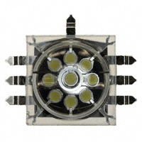
�10-Watt Lednium SMD
OVTL09LG3x Series Package Drawing:
OPTEK reserves the right to make changes at any time in order to improve design and to supply the best product possible. Issue B 0507 Page 2 of 11 OPTEK Technology Inc. — 1645 Wallace Drive, Carrollton, Texas 75006 Phone: (972) 323-2200 or (800) 341-4747 FAX: (972) 323-2396 visibleLED@optekinc.com www.optekinc.com
�10-Watt Lednium SMD
OVTL09LG3x Series Absolute Maximum Ratings
DC Forward Current Peak Pulsed Forward Current Reverse Voltage Maximum Allowable Junction Temperature2 Storage and Operating Temperature
Notes: 1. Pulse width 1 ms maximum, duty cycle 1/16. 2. Thermal resistance junction to board (TJB) is 2.5° C/W.
1
1.05 A 3A 15 V 130° C -50° ~ +85 ° C
Electrical Characteristics (IF = 1.05 A, TJ = 25° C)
SYMBOL PARAMETER
Forward Voltage (Amber) Forward Voltage (Blue)
MIN 5.7 8.7 9.6 5.7 8.5 8.7 -------------
TYP 6.9 10.2 10.8 6.9 9.2 10.2 -6.0 -4.8 -5.0 120
MAX 7.8 11.1 12.0 7.8 9.9 11.1 -------------
UNITS V V V V V V mV/° C mV/° C mV/° C deg
VF
Forward Voltage (Green) Forward Voltage (Red) Forward Voltage (Red/Green/Blue) Forward Voltage (White)
VF Temperature Co-efficient (Amber, Red) VF Temperature Co-efficient (White, Blue) VF Temperature Co-efficient (Green) 2 Θ½
50% Power Angle
Optical Characteristics (IF = 1.05 A, TJ = 25° C)
COLOR
Amber Blue Green Red DOMINANT WAVELENGTH MIN 590 455 510 620 TYP 595 460 515 625 MAX 600 465 520 630 SPECTRAL FULL-WIDTHHALF-MAXIMUM 16 nm 24 nm 40 nm 18 nm DOMINANT WAVELENGTH TEMPERATURE DEPENDENCE 0.08 nm/° C 0.05 nm/° C 0.04 nm/° C 0.05 nm/° C
Color
Cool White
Minimum CCT (° K) Maximum CCT (° K)
6400 7600 Cx Cy
Chromaticity Coordinates
.298 .314 .313 .341 .395 .372 .306 .288 .318 .300 .395 .390 .313 .34 .334 .326 .435 .426 .317 .307 .338 .382 .435 .443
Daylight White
5200
6400
Cx Cy Cx Cy
Warm White
3200
3800
OPTEK reserves the right to make changes at any time in order to improve design and to supply the best product possible. OPTEK Technology Inc. — 1645 Wallace Drive, Carrollton, Texas 75006 Phone: (972) 323-2200 or (800) 341-4747 FAX: (972) 323-2396 visibleLED@optekinc.com www.optekinc.com Issue B 0507 Page 3 of 11
�10-Watt Lednium SMD
OVTL09LG3x Series CIE Chromaticity Diagram
Y
X
Spatial Intensity Distribution
-100
-80
-60
-40
-20
0
20
40
60
80
100
Angle (degrees)
Normalized Spectral Intensity vs Angular Displacement
OPTEK reserves the right to make changes at any time in order to improve design and to supply the best product possible. Issue B 0507 Page 4 of 11 OPTEK Technology Inc. — 1645 Wallace Drive, Carrollton, Texas 75006 Phone: (972) 323-2200 or (800) 341-4747 FAX: (972) 323-2396 visibleLED@optekinc.com www.optekinc.com
�10-Watt Lednium SMD
OVTL09LG3x Series Typical Electro-Optical Characteristics Curves
Input Current = 1.05 A, TJ = 25° C Input Current = 1.05A, TJ = 25° C
Normalized Spectral Intensity
1.0 0.8 0.6 0.4 0.2 0.0 380
1.0
——Cool White
0.8 0.6 0.4 0.2 0.0 430 480 530 580 630 680 730 780 200 300 400 500 600 700 780
W avelength (nm)
W avelength Characteristics
Input Current = 1.05A, TJ = 25° C
W avelength Characteristics
Input Current = 1.05A, TJ = 25° C
Normalized Spectral Intensity
Normalized Spectral Intensity
1.0
——Daylight White
1.0
——Warm White
0.8 0.6 0.4 0.2 0.0 200 300 400 500 600 700 780
W avelength (nm)
0.8 0.6 0.4 0.2 0.0 200
300
400
500
600
700
780
W avelength (nm)
W avelength Characteristics
Luminosity normalized to TJ = 25° C
W avelength Characteristics
Luminosity normalized to TJ = 25° C
2.0 1.8 1.6 1.4 1.2 1.0 0.8 0.6 0.4 0.2 0.0 0 20 40 60 80 100 120 140 160
Junction Temperature ° C
OPTEK Part Number
OVTLO9LG3A OVTLO9LG3B OVTLO9LG3G OVTLO9LG3R OVTLO9LG3W OVTLO9LG3WD OVTLO9LG3WW
% Normalized Luminosity at Junction Temperature (° C)
0 125 107 110 135 105 105 105 25 100 100 100 100 100 100 100 50 85 95 95 90 93 93 93 75 70 87 85 75 82 82 82 100 60 75 70 65 68 68 68 125 45 65 65 50 60 60 60
Normalized Luminosity
Junction Temperature Characteristics
Junction Temperature Characteristics
OPTEK reserves the right to make changes at any time in order to improve design and to supply the best product possible. OPTEK Technology Inc. — 1645 Wallace Drive, Carrollton, Texas 75006 Phone: (972) 323-2200 or (800) 341-4747 FAX: (972) 323-2396 visibleLED@optekinc.com www.optekinc.com Junction Temperature ° C Issue B 0507 Page 5 of 11
�10-Watt Lednium SMD
OVTL09LG3x Series
IF vs VF
1600 1400 1200 1000 800 600 400 200 0 4.0 5.0 6.0
red amber blue green
IF (mA)
7.0
8.0 VF (V)
9.0
10.0
11.0
12.0
Forward Current vs. Forward Voltage
Derating of continuous forward current must be observed to prevent maximum junction temperature from being exceeded.
Derating of continuous forward current must be observed to prevent maximum junction temperature from being exceeded.
120 100
Maximum Current (%)
120 100 80 60 40 20 20 40 60 80 100 120 140 0 20 40 60 80 100 120 140
80 60 40 20 0
Ambient Temperature ° C
Maximum Current (%)
Ambient Temperature ° C
Derating Curves - Blue, Green and White LEDs
Derating Curves - Amber and Red LEDs
Critical Thermal Conditions (To maintain junction temperature (TJ) at 85° C)
WHEN MOUNTED ON: FR4 PC BOARD USE SAFE OPERATING CURRENT OF: 200 mA IMS 500 mA SPREADER PLATE 700 mA 3x3x1 in. FIN EXTRUSION 800 mA ACTIVE HEATSINK 1000 mA
NOTE: Refer to OPTEK Application Note #228 on thermal management (www.optekinc.com/pdf/AppNote228.pdf).
OPTEK reserves the right to make changes at any time in order to improve design and to supply the best product possible. Issue B 0507 Page 6 of 11 OPTEK Technology Inc. — 1645 Wallace Drive, Carrollton, Texas 75006 Phone: (972) 323-2200 or (800) 341-4747 FAX: (972) 323-2396 visibleLED@optekinc.com www.optekinc.com
�10-Watt Lednium SMD
OVTL09LG3x Series OPTEK 10-watt Lednium Markings
Θ
Cathode
OVTL09LG3X
Date Code-Batch Number
MALAYSIA
FRONT
BACK
Packaging: 25 pieces per tray
OPTEK’s Lednium Series Solid State Lighting products package the highest quality LED chips. Typically, the lumen output of these chips can be as high as 70% after 50,000 hours of operation. This prediction is based on specific test results and on tests on similar materials, and relies on strict observation of the design limits and ratings included in this data sheet.
OPTEK reserves the right to make changes at any time in order to improve design and to supply the best product possible. OPTEK Technology Inc. — 1645 Wallace Drive, Carrollton, Texas 75006 Phone: (972) 323-2200 or (800) 341-4747 FAX: (972) 323-2396 visibleLED@optekinc.com www.optekinc.com Issue B 0507 Page 7 of 11
�10-Watt Lednium SMD
OVTL09LG3x Series
Thermal Resistance
Optek Lednium Series 1-watt Cup – Measured value 2oC/w Optek Lednium Series 10-watt Matrix – Measured value 2.5oC/w
Theory In line with industry practice, the thermal resistance (Rth) of our LED packages is stated as Rθ j-b, thermal resistance from the junction region ( j ) of the die, to the board (b) - PCB or other mounting surface. What this means in a practical sense, is that when operating at rated input (1watt approx.) the junction of a die in a cup product will attain a temperature that is 2oC higher than a reference point on the mounting surface beneath it. In the case of a 10-watt Matrix product, the maximum temperature difference between any junction and the reference point is 25oC (2.5oC/w x 10w). The thermal path thus quantified is a composite of a number of thermally resistive elements in a series and or parallel configuration, but lumped together into a single parameter for convenience. For an end user of LED products then, this constant allows the junction temperature to be determined by a simple measurement of the temperature of the mounting surface. Optek recommends that the design value of sustained die junction temperature be limited to 80oC. In an ambient temperature of 25oC, the board temperature of a 10-watt device must be constrained below 55oC to comply with this recommendation, and for a 1-watt cup the board can theoretically operate at up to 78oC.
(OVTL01LGAxx) (OVTL09LG3xx)
From the diagram above it can be seen that the heat generated in the junction region follows a somewhat serial conductive path through the package to the major radiating surface – which in this example is a single sided PCB. Some additional radiation may occur directly from the upper surface of the package (not shown). This would be conducted upward from the die surface through the transparent encapsulating material to the package surface and be radiated from there. To all practical purposes this is a very minor effect. The polymer encapsulants in normal use are poor conductors of heat.
OPTEK reserves the right to make changes at any time in order to improve design and to supply the best product possible. Issue B 0507 Page 8 of 11 OPTEK Technology Inc. — 1645 Wallace Drive, Carrollton, Texas 75006 Phone: (972) 323-2200 or (800) 341-4747 FAX: (972) 323-2396 visibleLED@optekinc.com www.optekinc.com
�10-Watt Lednium SMD
OVTL09LG3x Series
Typical elements in the conducting path and corresponding nominal thermal conductivities are:
Elements Epilayers Substrate Die attach material Package Solder Copper cladding GaN/InGaN Sapphire Conductive epoxy Silver plated copper Solder (Sn/Ag/Cu) Copper
w/mK 150 50 10 350 35 300
Note : Thermal conductivity is a physical constant. For the materials above, the respective contribution each makes to the overall thermal resistance (Rθ j-b) is a function of the thickness of each material layer, and the surface area. Thermal Conductivity (TC) is defined to be the heat conducted in time (t), through thickness (T) in a direction normal to a surface area (A), due to a temperature difference (δT). Therefore TC= q/t x {T/[A x δT]} and δT = [Q x T]/[A x TC] where δT = Temp. difference (K) Q = Power (w) A = Surface area (m2) T = layer thickness (m) TC = Thermal Conductivity (w/mK)
Theoretical Calculation (for 1 watt dissipated in a cup product via a single 40mil die) GaN Thickness approx 10 x 10-6 Area 10-6 T = 60 x 10-6 T = 20 x 10-6 A = 2 x 10⁻⁶ T = 0.4x10⁻³ A = 6x10⁻⁶ T = 60x10-6 A = 6x10-6 = 1 x 10x10-6/ 10-6 x 150 = 0.07 K = 1 x 60x10-6/ 10-6 x 50 = 1.2 K = 1 x 20x10-6 / 2x10-6 x 10 =1 = 1 x 0.4x10-3/ 6x10-6 x 350 = 0.19 = 1 x 60x10-6/6x10-6 x 25 = 0.4 Total Calculated δT = 2.86K
Substrate Die attach
Package Solder
OPTEK reserves the right to make changes at any time in order to improve design and to supply the best product possible. OPTEK Technology Inc. — 1645 Wallace Drive, Carrollton, Texas 75006 Phone: (972) 323-2200 or (800) 341-4747 FAX: (972) 323-2396 visibleLED@optekinc.com www.optekinc.com Issue B 0507 Page 9 of 11
�10-Watt Lednium SMD
OVTL09LG3x Series
Power input is 1 watt; however, some power is converted into light energy. Assuming this is of the order of 200mw, the adjusted value of δT is 2.29K. The calculation now assumes that all of the dissipation, 800mw of heat, is conducted along the thermal path, thereby ignoring any conduction and subsequent radiation that is not directionally normal to the surfaces considered, ie: conduction through the encapsulant material vertically away from the board, and conduction horizontally away from the heat source. The calculation also assumes that there is no contribution to thermal resistance at the boundaries between material layers. In practice it is improbable that perfect transfer will occur at these transition regions, even though the bonding between layers in this example are of high quality. In general, the calculation indicates that the measurements below are of the order of magnitude that can be expected. The alternate matrix product range is of a much more complicated thermal design, which does not lend itself to a simple theoretical calculation similar to that shown above. There are multiple incident heat sources, parallel heat conduction paths, and significantly larger surface area for stray radiation, eg. Cup above has a surface area available for stray radiation of approximately, 25mm2 per watt of input power. A 10-watt matrix product has approximately 92.5mm2 of exposed surface per input watt.
Measurements The key to an accurate measurement of thermal resistance is to obtain a reliable value for the junction temperature (Tj). Since the die itself is, and must be, encapsulated during testing, and the junction is contained within the structure of the die, direct measurement of the junction temperature by normal means is not possible. Two methods of non-contact thermography are available, both of which rely on emitted infrared detection. Infrared imagery by calibrated radiograph is a possibility; however, in the instance of a cup product only a small value of δT is expected which makes accurate estimation of the actual temperature gradient difficult using colorimetry. The alternative measurement type is digital infrared thermography. This means there is an inherent uncertainty in the calculation algorithm, which sometimes gives results considered unacceptably inaccurate. In this instance absolute accuracy is of secondary importance because the value to be determined is a temperature difference (δT) which requires only relative values – any error in a first reading will also be present in subsequent readings that are about the same value. The difference between readings is accurate. The other significant drawback to infrared thermometers is a limitation to minimizing the spot size over which the measurement is made. This poses a difficulty for small assemblies like an LED cup, and in particular the added complication that the calculated temperature is an average value for the area being interrogated further complicates the issue. Another concern is sometimes raised about the ability of this type of instrument to detect a heated surface beyond the closest transparent radiating surface. This is a significant issue for far field measurements; however, it is simple to demonstrate that this does not hold true for the near field, and particularly when the incident beam has a known focal length.
OPTEK reserves the right to make changes at any time in order to improve design and to supply the best product possible. Issue B 0507 Page 10 of 11 OPTEK Technology Inc. — 1645 Wallace Drive, Carrollton, Texas 75006 Phone: (972) 323-2200 or (800) 341-4747 FAX: (972) 323-2396 visibleLED@optekinc.com www.optekinc.com
�10-Watt Lednium SMD
OVTL09LG3x Series
Measurement Instrument: IR Thermometer Auto ranging: -100 to 1200oC Spot size 3mm D. Focus 25.4mm Cup Product Input 350mA at 3.3V(1watt)
Averaged Test Results Tj Tb 32 30.2
δT 1.8
Rth 1.8oC/W
Matrix Product Input 1050mA at 10.2V(10.7watts) Averaged Test Results Tj Tb δT 89 62 27
Rth 2.52° C/W
OPTEK reserves the right to make changes at any time in order to improve design and to supply the best product possible. OPTEK Technology Inc. — 1645 Wallace Drive, Carrollton, Texas 75006 Phone: (972) 323-2200 or (800) 341-4747 FAX: (972) 323-2396 visibleLED@optekinc.com www.optekinc.com Issue B 0507 Page 11 of 11
�