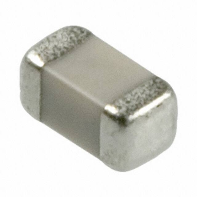
Thick Film Chip Resistors
(CR, CJ Series)
How to Order
CR 05 - 472 J - H
Features
• Low Noise
• Nickel Barrier Terminations
q
w
qSeries
CR : Resistor
CJ : Jumper
wSize(EIA)
Application
• General Purpose
03
05
10
Structure and material
Code
Structure
Material
A
A
B
B
C
D
E
e r t
Coating
Glass or Epoxy
Resistor
RuO2 Resistor
(The same material
of Termination for
chip jumper)
0201
0402
0603
21
32
0805
1206
eResistance Value(3 digits or 4 digits)
Ex. 562 : 56×102=5600Ω
4021 : 402×101=4020Ω
Chip Jumper : 000
rTolerance
D
±0.5%
J
±5%
F
±1%
Blank Jumper chips
tPackaging
Taping Paper φ178 4mm 5,000pcs
Taping Paper φ178 2mm 10,000pcs
T
∗H
∗ Available for CR05 and CR03
C
Substrate
96% Alumina
D
Termination
Silver
E
Plating
(Ni, Sn or Sn-Pb) Pla.
Dimensions
(Unit : mm)
L
W
W
Type(EIA Size)
c
d
d
C
d
T
CR03, CJ03(0201)
0.30±0.03 0.60±0.03 0.15±0.10 0.15±0.05 0.23±0.03
CR05, CJ05(0402)
0.50±0.05 1.00±0.05 0.20±0.15 0.20±0.10 0.35±0.05
CR10, CJ10(0603)
0.80 +0.15
−0.10
1.60±0.10 0.25±0.20
0.20+0.20
−0.15
CR21, CJ21(0805)
1.25 +0.15
−0.10
2.00±0.10 0.35±0.20 0.40±0.20 0.55±0.10
CR32, CJ32(1206)
1.55 +0.15
−0.10
3.10±0.10 0.45±0.20 0.45±0.20
0.50±0.10
0.55+0.10
−0.05
T
c
L
Specifications
Series
Rated Power
Max. Working Voltage
CR03(0201)
0.05(1/20)W
15V
J: ±5%
10Ω to 1MΩ
10Ω to 1MΩ
1.0Ω to 10MΩ
Resistance Tolerance
Resistance Value Range
CR05(0402)
0.0625(1/16)W
50V
F: ±1%
J: ±5%
CR10(0603)
0.10(1/10)W
50V
D: ±0.5%
F: ±1%
J: ±5%
10Ω to 1MΩ
10Ω to 1MΩ
1.0Ω to 10MΩ
10Ω to 1MΩ
10Ω to 1MΩ
1.0Ω to 10MΩ
10Ω to 1MΩ
10Ω to 1MΩ
1.0Ω to 10MΩ
CR21(0805)
0.125(1/8)W
100V
D: ±0.5%
F: ±1%
J: ±5%
CR32(1206)
0.25(1/4)W
200V
D: ±0.5%
F: ±1%
J: ±5%
Working Temperature
−55 to +125°C
�Thick Film Chip Resistors
(CR, CJ Series)
Specifications
How to Calculate Rated Voltage
• CJ series
E= P • R
E : Rated Voltage (V)
P : Rated Power (W)
R : Standard Resistance Value (Ω)
Rated voltage should be lower than max
working voltage.
Part Number
Rated Current
CJ03
Resistivity
Working Temperature
50mΩmax
−55 to +125°C
0.5A(70°C)
(0201 Type)
CJ05, CJ10, CJ21
1A(70°C)
(0402, 0603, 0805 Type)
CJ32
2A(70°C)
(1206 Type)
Recommended Land Pattern (Unit : mm)
Derating Curve
Rated power should be reduced as below when temperature become higher.
Under high temperature, power derated as follows:
C
100
B
80
EIA Size
A
B
C
0201
0.25
0.225
0.3
0402
0.5
0.4
0.5
0603
0.8
0.7
0.8
0805
1.0
0.8
1.2
Power Ratio(%)
A
B
60
40
125
20
0
-55
70
Ambient Temp (°C)
1206
2.0
0.8
Marking
1.5
Standard Resistance Value
E24
Resistance value (3 digits code)
(Ex.)47×103=47000(Ω)
=47(KΩ)
1.0
1.1
1.2
1.3
1.5
1.6
1.8
2.0
2.2
2.4
2.7
3.0
3.3
3.6
3.9
4.3
4.7
5.1
5.6
6.2
6.8
7.5
8.2
9.1
4R7 : 4.7Ω(The decimal point is shown by "R".)
100 : 10Ω
102 : 1kΩ
105 : 1MΩ
�Thick Film Chip Resistors
Tape & Reel
Tape & Reel
• Reel
(Unit : mm)
Code
A
Dimension
φ178±0.2
B
C
D
E
φ50min φ13.0±0.5 φ21.0±0.8 2.0±0.5
W
t
R
10.0±1.5
2.5max
1.0
E
B
C
D
R
t
A
W
• Carrier Tape
(Unit : mm)
TYPE
Feed Round
Perforated Square Holes
Holes
to Contain Each Resistor
J
Dimension
Code
A
B
0201
0.40±0.05 0.70±0.05
0402
0.65±0.1 1.15±0.1
C
D
E
G
H
J
t
0.45max
2.0±0.1
t
E
F
0.6max
D
B
C
A
F
H
0603
1.1±0.2
1.9±0.2
0805
1.65±0.2
2.4±0.2
1206
2.0±0.2
3.6±0.2
G
• Taping Quantity per reel
(Unit : pcs)
TYPE
Paper(φ178 reel)
0201
10000(2mm pitch)
0402
10000(2mm pitch)
0603
5000(4mm pitch)
0805
5000(4mm pitch)
1206
5000(4mm pitch)
8.0±0.2
3.5±0.05
1.75±0.1
2.0±0.05
4.0±0.1
4.0±0.1
φ1.5
+0.1
−0
1.1max
�Test Conditions and Standards
CR, CJ, CRA3A, CRB3A, CRC3A series
Electrical Characteristics
Standard
Test Conditions
Item
Resistor
DC Resistance
Temperature
Characteristics
Within Initial Tolerance
Resistance(Ω)
*D, F
10≤R≤1M
J, CR05:F
R
很抱歉,暂时无法提供与“CR10-1962F-T”相匹配的价格&库存,您可以联系我们找货
免费人工找货