TVL-55781GD050J-LW-G-AAN 数据手册
R
RooH
HS
S
C
CO
OM
MP
PLLIIA
AN
NT
T
APPROVAL SHEET
承 認 書
Customer
客戶名稱
Part No.
產品型號
Product type
產品內容
RoHS
綠色產品
TVL-55781GD050J-LW-G-AAN
5.0” TFT module: Transmissive Type, Positive mode,
RGB vertical stripe
□Non-compliance
■ Compliance
Remarks
備註欄
■Preliminary Specification 暫行規格
□Final Specification 正式規格
Signature by Customer:
客戶確認簽章:
Issued by
QA
TVL-55781AA
Checked by
QA
ver A
Checked by
PM
-1-
Approved By
QA
RD
Issue date: 2013/02/21
�R
RooH
HS
S
C
CO
OM
MP
PLLIIA
AN
NT
T
Specification of LCD Module
Product No.: TVL-55781GD050J-LW-G-AAN
Issue date: 2013/02/21
KYOCERA DISPLAY CORPORATION
5-7-18, Higashinippori Arakawa-ku ,
Tokyo 116-0014, Japan
TEL: +81-3-5811-8780
FAX: +81-3-5811-8782
TVL-55781AA
ver A
-2-
Issue date: 2013/02/21
�R
RooH
HS
S
C
CO
OM
MP
PLLIIA
AN
NT
T
TABLE OF CONTENTS
1. REVISION HISTORY......................................................................... 5
2. GENERAL DESCRIPTION ................................................................ 6
3. FEATURES ....................................................................................... 6
4. MECHANICAL SPECIFICATION ...................................................... 6
5. MECHANICALDIMENSION............................................................... 7
6. MAXIMUM RATINGS ........................................................................ 8
7. ELECTRICAL CHARACTERISTICS ................................................. 9
7.1.
7.2.
TFT LCD Characteristic .................................................................................. 9
Backlight Characteristic .................................................................................. 9
8. MODULE FUNCTION DESCRIPTION ............................................ 10
8.1.
8.2.
PIN Description ............................................................................................. 10
Timing characteristics ................................................................................... 13
9. ELECTRO-OPTICAL CHARACTERISTICS .................................... 15
10. RELIABILITY................................................................................... 17
10.1.
TESTS....................................................................................................... 17
11. INSPECTION CRITERIA ................................................................. 18
11.1.
Acceptable quality level(MIL-STD-105E LEVELⅡ )................................... 18
11.2.
11.3.
11.4.
Definition of inspection area ...................................................................... 18
Basic conditions for inspection .................................................................. 19
Inspection Item and Criteria ...................................................................... 19
12. ILLUSTRATION OF LCD DATE CODE........................................... 23
13. PACKAGING................................................................................... 23
13.1.
Procedure.................................................................................................. 23
14. ROHS COMPLIANT WARRANTY................................................... 23
15. PRECAUTIONS FOR USE .............................................................. 23
TVL-55781AA
ver A
-3-
Issue date: 2013/02/21
�R
RooH
HS
S
C
CO
OM
MP
PLLIIA
AN
NT
T
15.1.
15.2.
Safety ........................................................................................................ 23
Storage Conditions.................................................................................... 23
15.3.
15.4.
Installing LCD Module ............................................................................... 24
Precautions For Operation ........................................................................ 24
15.5.
15.6.
Handling Precautions ................................................................................ 24
Warranty.................................................................................................... 25
TVL-55781AA
ver A
-4-
Issue date: 2013/02/21
�R
RooH
HS
S
C
CO
OM
MP
PLLIIA
AN
NT
T
1. REVISION HISTORY
Version
A
TVL-55781AA
Revise record
New version
ver A
Date
2012/6/11
-5-
Issue date: 2013/02/21
�R
RooH
HS
S
C
CO
OM
MP
PLLIIA
AN
NT
T
2. GENERAL DESCRIPTION
TVL-55781GD050J-LW-G-AAN is a Transmissive type color active matrix liquid crystal
display (LCD), which uses amorphous thin film transistor (TFT) as switching devices.
This product is composed of a TFT LCD panel, driver ICs, FPC, and a backlight unit.
The following table described the features of TVL-55781GD050J-LW-G-AAN.
3. FEATURES
Transmissive Type
Display Mode
Amorphous TFT LCD
Normally white
Display Format
RGB Stripe type
Color
262K Color
Interface
RGB data bus, 18 bit parallel data
Viewing Direction
6 O’clock
Backlight type / color
LED / White
4. MECHANICAL SPECIFICATION
Item
Specifications
Unit
120.7 (W) × 75.8 (H) × 3.15 (D)*
mm
Resolution
480×3(R,G,B)×272
dot
Active area
110.88 (W) × 62.832 (H)
mm
Dot pitch
0.231 (W) × 0.231 (H)
mm
Polarizer
Anti-Glare (Haze:40%)
Dimensional outline
* Exclude FPC
TVL-55781AA
ver A
-6-
Issue date: 2013/02/21
�R
RooH
HS
S
C
CO
OM
MP
PLLIIA
AN
NT
T
5. MECHANICALDIMENSION
TVL-55781AA
ver A
-7-
Issue date: 2013/02/21
�R
RooH
HS
S
C
CO
OM
MP
PLLIIA
AN
NT
T
6. MAXIMUM RATINGS
ITEM
Digital supply voltage
Power Supply for Pump
SYMBOL
AVDD
MIN.
MAX.
UNIT
-0.5
+5.0
V
-0.3
+7.0
V
V
Logic supply voltage
DVDD
-0.5
+5.0
Operation Temperature
TA
-20
85
Storage Temperature
Tstg
-40
85
IF
-
30
Single LED forward current
Note:
mA
0. All of voltage listed above are with respective to GND=VSS=0V.
b. Device is subject to be damaged permanently if stresses beyond those absolute
maximum ratings listed above.
C: TA≦40℃ Without dewing.
TVL-55781AA
ver A
-8-
Issue date: 2013/02/21
�R
RooH
HS
S
C
CO
OM
MP
PLLIIA
AN
NT
T
7. ELECTRICAL CHARACTERISTICS
7.1.TFT LCD Characteristic
Typical operating conditions
Item
(GND=DGND=AGND=0V)
Symbol
Min.
Typ.
Max.
Unit
3.0
3.3
3.6
V
3.0
3.3
3.6
V
CPSEL=”L”
(Default)
2.6
2.7
3.0
V
CPSEL=”H”
Digital power supply
AVDD
Charge Pump Supply
Voltage
Digital interface supply
Voltage
DVDD
1.8
AVDD
Driver Input signal
H
VIH
0.7*DVDD
-
DVDD
V
voltage
L
VIL
GND
-
0.3*DVDD
V
IDD
-
22.5
mA
Supply current
Note
7.2.Backlight Characteristic
Item
Symbol
Power
Consumption
Values
Unit
Min.
Typ.
Max.
PLED
-
924
-
mW
LED Current
IL
-
40
-
mA
LED Voltage
VL
19.6
-
24.5
V
Remark
Note1: Kyocera Display suggests using constant current driving
this backlight unit.
Note2: LED structure unit.
2W/3
W/3
2H/3
○
1
○
2
○
3
○
4
○
5
○
6
○
7
○
8
○
9
Active area (H)
H/3
Active area
TVL-55781AA
ver A
-9-
Issue date: 2013/02/21
�R
RooH
HS
S
C
CO
OM
MP
PLLIIA
AN
NT
T
8. MODULE FUNCTION DESCRIPTION
8.1.PIN Description
Pin
Symbol
I/O
1
2
VLEDVLED+
P
P
Power for LED backlight cathode
Power for LED backlight anode
3
DGND
P
Ground for digital circuit
4
NC
-
No connection
5
NC
-
No connection
6
NC
-
No connection
7
NC
-
No connection
8
AGND
P
Ground for analog circuit
9
VGH
C
Stabilizing capacitor (2.2uF/25V)
10
C5M
C
Booster capacitor (2.2uF/6.3V)
11
C5P
C
Booster capacitor (2.2uF/6.3V)
12
13
C1AP
C1AM
C
C
14
VGL
C
15
C1BP
C
Booster capacitor (2.2uF/6.3V)
Booster capacitor (2.2uF/6.3V)
Stabilizing capacitor (2.2uF/16V + Schottky
diode ; Turn on voltage = 0.2V)
Booster capacitor (2.2uF/6.3V)
16
C1BM
C
Booster capacitor (2.2uF/6.3V)
17
AGND
P
Ground for analog circuit
18
VCC25
C
Stabilizing capacitor (2.2uF/6.3V)
19
C4P
C
Booster capacitor (1uF/16V)
20
C4M
C
21
AVDD
22
ID2
23
AGND
24
VCC
C
Stabilizing capacitor (2.2uF/6.3V)
25
C3P
C
Booster capacitor (1uF/16V)
26
C3M
C
Booster capacitor (1uF/16V)
TVL-55781AA
ver A
Function
Remark
25V為
耐壓值
Booster capacitor (1uF/16V)
Digital and Charge pump supply voltage input
P
pin for Booster circuit (3.3V) + (4.7uF/6.3V)
I/O High – high (Connect to AVDD on FPC)
P Ground for analog circuit
-10-
Issue date: 2013/02/21
�R
RooH
HS
S
C
CO
OM
MP
PLLIIA
AN
NT
T
27
ID1
28
GRB
I
System reset pin (active low)
29
PGND
P
Ground for booster circuit
30
DVDD
P
31
CAVDD
C
Stabilizing capacitor (4.7uF/10V)
32
PGND
P
Ground for booster circuit
33
STB
I
Standby control signal
34
CSB
I
Chip select pin for serial interface
35
SDA
I
Data input pin in serial mode
36
SCL
I
Clock input pin in serial mode
37
VINT2
C
Stabilizing capacitor (2.2uF/16V)
38
DEN
I
Display enable pin from controller
39
B7
I
Blue data
40
B6
I
Blue data
41
B5
I
Blue data
42
B4
I
Blue data
43
B3
I
Blue data
44
B2
I
Blue data
45
G7
I
Green data
46
G6
I
Green data
47
G5
I
Green data
48
G4
I
Green data
49
G3
I
Green data
50
G2
I
Green data
51
R7
I
Red data
52
R6
I
Red data
53
R5
I
Red data
54
R4
I
Red data
55
R3
I
Red data
56
R2
I
Red data
57
NC
-
No connection
58
NC
-
No connection
59
CLK
I
Dot-clock and oscillator source
60
VINT1
C
Stabilizing capacitor (4.7uF/10V)
TVL-55781AA
ver A
I/O Connect to AVDD on FPC
Digital interface supply voltage input
(1.8V/3.3V) + (2.2uF/6.3V)
-11-
Issue date: 2013/02/21
�R
RooH
HS
S
C
CO
OM
MP
PLLIIA
AN
NT
T
61
PGND
P
Ground for booster circuit
62
VINT3
C
Stabilizing capacitor (4.7uF/10V)
63
VCOMH
C
Stabilizing capacitor (4.7uF/6.3V)
64
VCOML
C
Stabilizing capacitor (4.7uF/6.3V)
65
DGND
P
Ground for digital circuit
66
C2P
C
Booster capacitor (1uF/10V)
67
C2M
C
Booster capacitor (1uF/10V)
TVL-55781AA
ver A
-12-
Issue date: 2013/02/21
�R
RooH
HS
S
C
CO
OM
MP
PLLIIA
AN
NT
T
8.2.Timing characteristics
8.2.1.Timing Chart.
8.2.2.Timing Specification
TVL-55781AA
ver A
-13-
Issue date: 2013/02/21
�R
RooH
HS
S
C
CO
OM
MP
PLLIIA
AN
NT
T
8.2.3.Color data Assignment
[NOTE]:
2) Definition of Gray level : Color(n) : n to show the Gray level,n is the more high and the light more bright.
3) Data:1-High, 0-Low.
TVL-55781AA
ver A
-14-
Issue date: 2013/02/21
�R
RooH
HS
S
C
CO
OM
MP
PLLIIA
AN
NT
T
9. ELECTRO-OPTICAL CHARACTERISTICS
The following items are measured under stable conditions. The optical characteristics
should be measured in dark room or equivalent state with the methods shown in Note 1.
Item
Symbol Condition
Min
Typ
Max
Unit Remark
2
Brightness
400
cd/m
Note 2
Uniformity
75
%
Response time
TR+TF Θ=0
25
ms Note 3
At the
center
Contrast ratio
CR
500
Note 4
point of
A.A.
Color
Chromaticity White
Wx
Wy
0.27
0.27
Θ=0
NTSC
12’
3’
6’
9’
Viewing
Angle
φH
θR
φL
θL
CR 10
0.31
0.31
70
0.35
0.35
50
65
60
65
-
Note 5
%
Degree Note 6
Ta=25±2
Note:
1. Testing condition:
Stabilizing and leaving the panel only at room temperature for 30 minutes
The measurement should be executed in a stable, windless, and dark
room.
The Optical specifications are measured by Topcon BM-5A with a
viewing angle of 2° at a distance of 50cm.
2. Brightness= Nine-point average measurement.
Brightness Min.
Uniformity =
X 100%
Brightness Max.
3. Definition of response time: TR and TF
The figure below is the output signal of the photo detector.
TVL-55781AA
ver A
-15-
Issue date: 2013/02/21
�R
RooH
HS
S
C
CO
OM
MP
PLLIIA
AN
NT
T
Display Area
Optical
Response
White
100%
Black
White
TR
TF
90%
10%
0%
Time
4.
Definition of contrast ratio:
Contrast
(CR) =
ratio
Brightness measured when LCD is at
“white state”
Brightness measured when LCD is at
“black state”
5.
Measured at the center area of the panel when all the input terminals of
LCD panel are electrically opened.
Definition of viewing angle:
TVL-55781AA
ver A
-16-
Issue date: 2013/02/21
�R
RooH
HS
S
C
CO
OM
MP
PLLIIA
AN
NT
T
10.RELIABILITY
10.1.TESTS
NO.
1
2
3
4
ITEM
CONDITION
CRITERION
High Temperature
Operating Life test
85℃ 120 hrs
High Temperature
70℃ 240 hrs
operating test in the chamber
- 30℃ 240 hrs
2. Function check should be
executing immediately after
85℃ 240 hrs
the storage test.
1. Function check should be
executing immediately during
Operating Life test
Low Temperature
Operating Life test
High Temperature
Storage test
Low Temperature
Storage test
-40℃ 240hrs
5
6
Humility test
60℃*90%RH 240 hrs
-30℃
7
Thermal Shock
8
Electrical Static
Discharge
(30min)
10 cycle
(5min)
+80℃,
(30min)
Contact: ±4KV, 150pF/330Ω
Non-contact:±8KV,150pF/330Ω
FPC pin: ±2KV, 150pF/330Ω
5 times to every corners of
active area.
Vdd & Vss pin
Note 1: The sampling above is individual for each reliability test item.
Note 2: The color fading of polarizing filter should not care.
Note 3: All of the reliability testing chamber above, is using D.I. water.(Min value:1.0 MΩ
-cm)
Note 4: In case of malfunction defect caused by ESD damage, if it would be recovered
to normal state after resetting, it would be judged as a good part.
Note 5: In the case of cosmetic defect at 85℃/120 hrs test, as long as the module
appears to be in the same aspect as before the test when recovering to 70℃,
the module would be judged as normal.
TVL-55781AA
ver A
-17-
Issue date: 2013/02/21
�R
RooH
HS
S
C
CO
OM
MP
PLLIIA
AN
NT
T
11.INSPECTION CRITERIA
11.1.Acceptable quality level(MIL-STD-105E LEVELⅡ )
The AQL define:
Inspection Item
Major defect
Minor defect
Cosmetic
1.0%
1.5%
Electrical test
0.4%
0.65%
11.2.Definition of inspection area
V.A: Viewing Area
A.A: Active Area
End
BM area
Active Area
ITO area
Test pad & bonding
Terminal
Panel
十
Non-terminal
TVL-55781AA
ver A
-18-
Issue date: 2013/02/21
�R
RooH
HS
S
C
CO
OM
MP
PLLIIA
AN
NT
T
11.3.Basic conditions for inspection
11.3.1.Environment lamp under 1000±200 lux, Viewing direction for inspection
over 30 ㎝.
11.3.2.The distance from eye to defect around 200mm, the distance from ND
Filter to defect around 25~30mm.(Only MURA Defect)
Eye
200mm
ND Filter
Defect place
11.4.Inspection Item and Criteria
11.4.1.Cosmetic criterion
(1) Glass defect
No
Defect
Criteria
Dimension
Remark
By engineering diagram
Y
Z
1
(Minor)
X
Extensive crack 【Reject】
Cracks
2
(Major)
(2) LCM appearance defect within A.A (Without Touch Panel)
No
Defect
Criteria
Round type
Permissible Q’ty 1.ψ =(L+W)/2,
Spec.
(Minor) ψ 1.5mm or L>2.0mm
0
2. Disregard if out of A.A.
3
(Minor)
Permissible Q’ty 1.ψ =(L+W)/2 ,
Polarizer Bubble /
Spec.
Dent
ψ
TVL-55781GD050J-LW-G-AAN 价格&库存
很抱歉,暂时无法提供与“TVL-55781GD050J-LW-G-AAN”相匹配的价格&库存,您可以联系我们找货
免费人工找货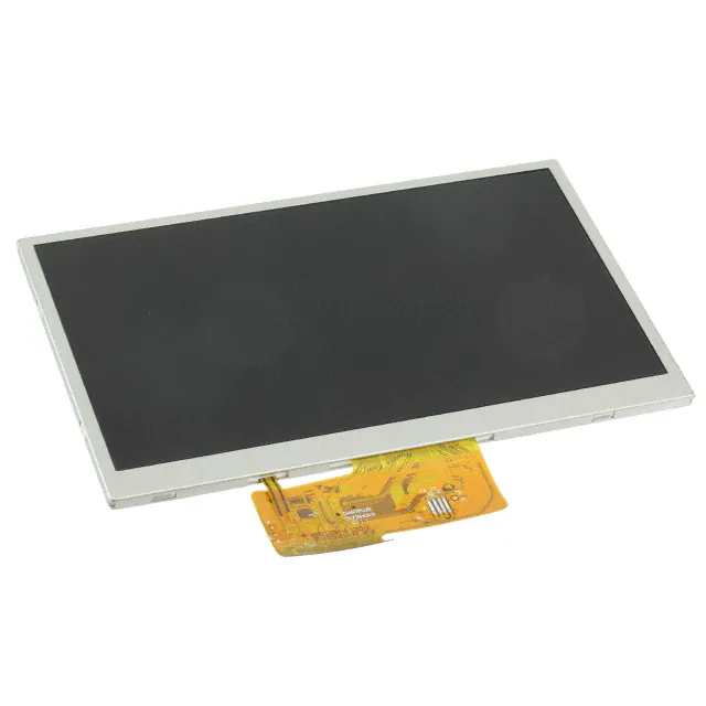


 工商网监
湘ICP备2023018690号
工商网监
湘ICP备2023018690号