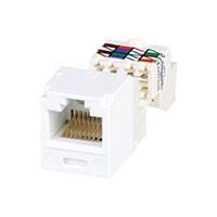
Mini-Com TX6 ™ PLUS UTP Jack Module
®
SPECIFICATION SHEET
specifications
Category 6/Class E, 8-position, UTP jack module shall
terminate solid, 4-pair, 24 – 22 AWG, 100 ohm unshielded
twisted pair cable and shall not require use of a punchdown
tool. UTP jack modules shall use a forward motion termination
method to optimize performance by maintaining cable pair
geometry while eliminating conductor untwist. The termination
cap shall be color-coded white to designate Category 6
performance and shall include a universal label coded for
T568A and T568B wiring schemes.
TX6 ™ PLUS UTP
Copper Cabling System
Mini-Com ® TX6 ™ PLUS
UTP Jack Module
Jack module:
technical information
Category 6/Class E channel
and component performance:
FCC and ANSI compliance:
PoE compliance:
IEC compliance:
RoHS compliance:
UL rated:
Conductor termination range:
Exceeds channel requirements of ANSI/TIA-568-C.2 Category 6
and ISO 11801 Class E standards at swept frequencies
1 to 250 MHz
Exceeds component requirements of ANSI/TIA-568-C.2 Category 6
and ISO 11801 Class E standards at swept frequencies
1 to 250 MHz
Meets all applicable ANSI/TIA-968-A requirements; contacts plated
with 50 microinches of gold for superior performance
Meets requirements of IEEE 802.3af and IEEE 802.3at for
PoE applications
Meets IEC 60603-7
Compliant
UL 1863 approved
Wire cap compatible with 24 – 22 AWG solid cable with conductor
insulation diameters of 0.035 in. to 0.048 in. and overall cable O.D.
0.200 in. to 0.330 in.
key features and benefits
100% performance tested
Utilizes enhanced
Giga-TX ™ Technology
Improved termination cap
Modular
True strain relief
Individually serialized
RJ45 interface
Identification
Termination tools (optional)
Block out device (optional)
Confidence that each jack module will deliver the critical
electrical performance requirements
Optimizes performance by eliminating conductor untwist and
reduces installation time and expense
Conductor retention slots simplify jack module termination
UTP jack modules snap in and out of all Mini-Com® Faceplates,
Modular Patch Panels and Surface Mount Boxes for easy moves,
adds and changes
Controls cable bend radius for long term installed performance
Marked with quality control number for future traceability
Industry standard interface provides a quick and easy plug and
play connection to RJ45 patch cords; backwards compatible
Can be clearly identified with optional labels and icons for
port identification
CGJT termination tool ensures conductors are fully terminated
by utilizing a smooth forward motion without impact on critical
internal components for maximum reliability
Provides a simple and secure method to control access to data
ports while not in use
applications
Mini-Com® TX6™ PLUS UTP Jack Modules are a
support the following applications:
component of the TX6™ PLUS UTP Copper Cabling
• Ethernet 10BASE-T, 100BASE-T (Fast
System. This end-to-end system is interoperable and
Ethernet), 1000BASE-T (Gigabit Ethernet)
backwards compatible, providing design flexibility to
• 155 Mb/s ATM, 622 Mb/s ATM, 1.2 Gb/s ATM
protect network investments well into the future. With
certified performance to the ANSI/TIA-568-C.2
• Token Ring 4/16
Category 6 and ISO 11801 Class E standards, this
• Digital video and broadband/baseband
system is ideal for today's high performance
analog video
workstation applications. With certified performance
• Voice over Internet Protocol (VoIP)
to the ANSI/TIA-568-C.2 Category 6 and ISO 11801
Class E Edition 2.1 standards, these systems will
w w w. p a n d u i t . c o m
CJ688TPIW*
TX6000 ™ UTP Copper Cable
Plenum:
Riser:
LSZH:
CM:
PUP6004**
PUR6004**
PUL6004**
PUC6004**
TX6 ™ PLUS UTP Patch Cords
CM (foot lengths):
UTPSP^Y
CM (meter lengths): UTPSP^^MY
LSZH
UTPSPL^^MY
(meter lengths):
Mini-Com ® Angled
Modular Patch Panels
24-port, 1 RU:
48-port, 2 RU:
CPPLA24WBLY
CPPLA48WBLY
Mini-Com ® Flat Modular
Patch Panels
24-port, 1 RU:
48-port, 2 RU:
CPPL24WBLY
CPPL48WBLY
For additional modular and punchdown patch
panels, visit www.panduit.com.
Tools and Accessories
Jack module
termination tool:
Wire snipping tool:
Wire snipping tool:
Clear dust cap:
Block out device:
Phone icons:
Data icons:
CGJT
CWST
CJAST
MDC-C
PSL-DCJB-^^^
CIPIW-C+
CIDIW-C+
*To designate color other than IW (Off White),
replace IW suffix with EI (Electric Ivory),
IG (International Gray), WH (White),
AW (Arctic White), BL (Black), BU (Blue),
RD (Red), YL (Yellow), GR (Green),
OR (Orange), or VL (Violet).
**To designate color, add suffix BU (Blue)
or WH (White). For additional cable colors,
contact customer service.
^For lengths 1 to 20 feet (one foot increments)
and 25, 30, 35, 40 feet, change the length
designation in the part number to the desired
length. For standard cable colors other than
Off White, add suffix BL (Black), BU (Blue), RD
(Red), YL (Yellow), GR (Green), OR (Orange)
or VL (Violet). For example, the part number
for a blue 15-foot patch cord is UTPSP15BUY.
^^For lengths 1 to 10 meters (one meter
increments) and 0.5, 1.5, 2.5, 15, 20, meters,
change the length designation in the part
number to the desired length. For standard
cable colors other than Off White, add suffix
BL (Black), BU (Blue), RD (Red), YL (Yellow),
GR (Green), OR (Orange) or VL (Violet). For
example, the part number for a blue 15-meter
patch cord is UTPSP15MBUY.
^^^To designate color other than Red, add
suffix BL (Black), BU (Blue), YL (Yellow), GR
(Green), OR (Orange), IW (Off White) or IG
(International Gray) at end of the part number.
10/package.
+To designate color other than IW (Off White),
replace IW with EI (Electric Ivory), IG
(International Gray), BL (Black), BU (Blue), RD
(Red), YL (Yellow), GR (Green), OR (Orange)
or VL (Violet) in the part number. 100/package.
Contact customer service for bulk packaged
jack modules and patch cords.
�Mini-Com ® TX6 ™ PLUS UTP Jack Module
Te s t R e s u l t s
Test Method
20 MHz
Category 6
ANSI/TIA-568-C.2
Standard
> 68.0
> 64.0
> 57.1
> 54.1
< 0.10
> 30
Performance Test
NEXT
PS NEXT
FEXT
PS FEXT
Attenuation
Return Loss
Typical Test Results (dB)
100 MHz
200 MHz
> 54.0
> 50.0
> 43.1
> 40.1
< 0.20
> 24.0
>
>
>
>
<
>
250 MHz
48.0
44.0
37.1
34.1
0.28
18.0
>
>
>
>
<
>
46.0
42.0
35.1
32.2
0.32
16.0
Consult technical support for cable brand specific channel test results.
Test Method
–
IEC 512-6d
IEC 512-9a
IEC 512-13b
Measurement
Load (grams)
Circuit Resistance (mOhms)
Circuit Resistance (mOhms)
Mating Force (N)
Unmating Force (N)
Typical Test Results
Normal Force
Vibration
Durability
Mating/Unmating
Mechanical Test
Electrical Test
Low Level Circuit Resistance
Dielectric Withstand Voltage
Insulation Resistance
Test Method
IEC 512-2a
IEC 512-4a
IEC 512-3a
Measurement
Resistance (mOhms)
1000 VAC, 1 minute
Resistance (MOhms)
Typical Test Results
Environmental Test
Temperature Life
Humidity
Thermal Shock
Climatic Sequence
Flowing Mixed Gas Corrosion
Test Method
IEC 512-9b
IEC 512-11c
IEC 512-11d
IEC 512-11a
IEC 512-11g
Circuit
Circuit
Circuit
Circuit
Circuit
>100
< 40
< 40
< 20
< 20
< 40
Passed
> 500
Measurement
Resistance (mOhms)
Resistance (mOhms)
Resistance (mOhms)
Resistance (mOhms)
Resistance (mOhms)
Typical Test Results
<
<
<
<
<
40
40
40
40
40
.71
[18.08]
Twist
Preservation Cap
.63
[15.88]
1.43
[36.37]
Module Housing
Dimensions are in inches. [Dimensions in brackets are metric].
WORLDWIDE SUBSIDIARIES AND SALES OFFICES
PANDUIT CANADA
Markham, Ontario
cs-cdn@panduit.com
Phone: 800.777.3300
PANDUIT EUROPE LTD.
London, UK
cs-emea@panduit.com
Phone: 44.20.8601.7200
PANDUIT SINGAPORE PTE. LTD.
Republic of Singapore
cs-ap@panduit.com
Phone: 65.6305.7575
PANDUIT JAPAN
Tokyo, Japan
cs-japan@panduit.com
Phone: 81.3.6863.6000
PANDUIT LATIN AMERICA
Guadalajara, Mexico
cs-la@panduit.com
Phone: 52.33.3777.6000
PANDUIT AUSTRALIA PTY. LTD.
Victoria, Australia
cs-aus@panduit.com
Phone: 61.3.9794.9020
For a copy of Panduit product warranties, log on to www.panduit.com/warranty
For more information
Visit us at www.panduit.com
Contact Customer Service by email: cs@panduit.com
or by phone: 800.777.3300 and reference COSP14
©2010 Panduit Corp.
ALL RIGHTS RESERVED.
WW-COSP14
11/2010
�


 工商网监
湘ICP备2023018690号
工商网监
湘ICP备2023018690号
