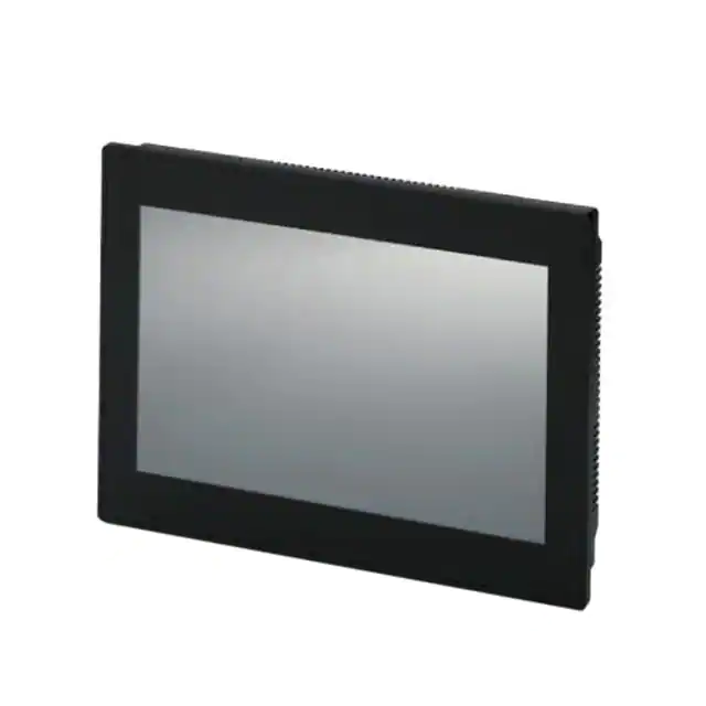
Touch Panels with TFT-Display
User manual
�User manual
Touch Panels with TFT-Display
2018-01-23
Designation:
UM EN BTP 2XXXX
Revision:
00
Order No.:
—
This user manual is valid for:
Designation
Order No.
BTP 2043W
BTP 2070W
BTP 2102W
1050387
1046666
1046667
PHOENIX CONTACT
108245_en_00
�How to contact us
Internet
Up-to-date information on Phoenix Contact products and our Terms and Conditions can be
found on the Internet at:
phoenixcontact.com
Make sure you always use the latest documentation.
It can be downloaded at:
phoenixcontact.net/products
Subsidiaries
If there are any problems that cannot be solved using the documentation, please contact
your Phoenix Contact subsidiary.
Subsidiary contact information is available at phoenixcontact.com.
Published by
PHOENIX CONTACT GmbH & Co. KG
Flachsmarktstraße 8
32825 Blomberg
GERMANY
Should you have any suggestions or recommendations for improvement of the contents and
layout of our manuals, please send your comments to
tecdoc@phoenixcontact.com
General terms and conditions of use for technical documentation
Phoenix Contact reserves the right to alter, correct, and/or improve the technical documentation and the products described in the technical documentation at its own discretion and
without giving prior notice, insofar as this is reasonable for the user. The same applies to any
technical changes that serve the purpose of technical progress.
The receipt of technical documentation (in particular user documentation) does not constitute any further duty on the part of Phoenix Contact to furnish information on modifications
to products and/or technical documentation. You are responsible to verify the suitability and
intended use of the products in your specific application, in particular with regard to observing the applicable standards and regulations. All information made available in the technical
data is supplied without any accompanying guarantee, whether expressly mentioned, implied or tacitly assumed.
In general, the provisions of the current standard Terms and Conditions of Phoenix Contact
apply exclusively, in particular as concerns any warranty liability.
This manual, including all illustrations contained herein, is copyright protected. Any
changes to the contents or the publication of extracts of this document is prohibited.
Phoenix Contact reserves the right to register its own intellectual property rights for the product identifications of Phoenix Contact products that are used here. Registration of such intellectual property rights by third parties is prohibited.
Other product identifications may be afforded legal protection, even where they may not be
indicated as such.
PHOENIX CONTACT
�BTP 2XXXX
PHOENIX CONTACT
�Table of Contents
Table of Contents
1
2
3
4
5
Important Notes .........................................................................................................................7
1.1
Symbols ................................................................................................................ 7
1.2
Safety Notes.......................................................................................................... 7
1.3
Intended Use ......................................................................................................... 8
1.4
Target Group ......................................................................................................... 8
Installation and Commissioning .................................................................................................9
2.1
Unpacking the Device............................................................................................ 9
2.2
Mounting the Device............................................................................................ 10
2.2.1
Mounting Cutout .................................................................................. 11
2.2.2
Side View, Mounting Depth .................................................................. 14
2.3
Connecting the Device ........................................................................................ 17
2.3.1
Supply Voltage ..................................................................................... 17
2.4
Switching On ....................................................................................................... 18
2.4.1
Settings and Functions ........................................................................ 19
2.5
Visualization ........................................................................................................ 25
2.5.1
System Variables ................................................................................. 26
2.6
Identification ........................................................................................................ 28
Control and Display Elements ..................................................................................................29
3.1
Touchscreen ....................................................................................................... 29
3.2
Display................................................................................................................. 29
Interfaces of the Device ...........................................................................................................31
4.1
USB (HOST)........................................................................................................ 32
4.1.1
Cable ................................................................................................... 32
4.2
USB (SLAVE) ...................................................................................................... 32
4.2.1
Cable ................................................................................................... 32
4.3
Ethernet............................................................................................................... 33
4.3.1
Pin Assignment .................................................................................... 33
4.3.2
Cable ................................................................................................... 33
4.4
RS-232 / RS-422 / RS-485 (COM1/COM2) ......................................................... 34
4.4.1
Pin Assignment .................................................................................... 34
4.5
Memory Card....................................................................................................... 35
4.6
Shielding D-SUB Connectors .............................................................................. 35
Maintenance and Servicing ......................................................................................................37
5.1
108245_en_00
Maintenance Interval ........................................................................................... 37
PHOENIX CONTACT
5
�BTP 2XXXX
6
6
5.2
Front Panel .......................................................................................................... 37
5.3
Battery ................................................................................................................. 37
Technical Data .........................................................................................................................39
PHOENIX CONTACT
6.1
General................................................................................................................ 39
6.2
BTP 2043W ......................................................................................................... 41
6.3
BTP 2070W ......................................................................................................... 42
6.4
BTP 2102W ......................................................................................................... 43
108245_en_00
�Important Notes
1
Important Notes
1.1
Symbols
The symbols in this manual are used to draw your attention on notes and dangers.
This symbol indicates hazards that could lead to personal injury.
There are three signal words indicating the severity of a potential injury.
DANGER
Indicates a hazard with a high risk level. If this hazardous situation is not avoided, it will
result in death or serious injury.
WARNING
Indicates a hazard with a medium risk level. If this hazardous situation is not avoided, it
could result in death or serious injury.
CAUTION
Indicates a hazard with a low risk level. If this hazardous situation is not avoided, it could
result in minor or moderate injury.
This symbol together with the NOTE signal word alerts the reader to a situation which may
cause damage or malfunction to the device, hardware/software, or surrounding property.
Here you will find additional information or detailed sources of information.
1.2
–
–
–
–
–
–
108245_en_00
Safety Notes
Read this manual carefully before using the operating device. Keep this manual in a
place where it is always accessible to all users.
Proper transportation, handling and storage, placement and installation of this product
are prerequisites for its subsequent flawless and safe operation.
This user manual contains the most important information for the safe operation of the
device.
The user manual, in particular the safety notes, must be observed by all personnel
working with the device.
Observe the accident prevention rules and regulations that apply to the operating site.
Installation and operation must only be carried out by qualified and trained personnel.
PHOENIX CONTACT
7
�BTP 2XXXX
The following notes apply to use in hazardous locations (UL / cUL Class I, Division 2,
Groups A, B, C and D). Suitable operating devices for this area are labeled accordingly. In
addition, the approvals for your operating device can be found in the technical data in the
user manual.
WARNING: Explosion hazard
Labeled and approved devices are suitable for use in Class I, Division 2, Groups A, B, C
and D or non-hazardous locations only.
Do not disconnect while the circuit is live or unless the area is known to be free of ignitable
concentrations.
Substitution of components may impair suitability for Class I, Division 2.
USB ports may only be connected or disconnected in an area known to be non-hazardous.
This product contains batteries, they must only be changed in an area known to be nonhazardous and may only be replaced by qualified service personal.
1.3
–
–
–
Intended Use
The device is designed for use in the industry.
The device is state-of-the art and has been built to the latest standard safety requirements. However, dangerous situations or damage to the machine itself or other property can arise from the use of this device.
The device fulfills the requirements of the EMC directives and harmonized European
standards. Any modifications to the system can influence the EMC behavior.
NOTICE: Radio Interference
This is a class A device. This device may cause radio interference in residential areas. In
this case, the user may be required to introduce appropriate countermeasures, and to
bear the cost of same.
1.4
Target Group
The use of products described in this manual is oriented exclusively to:
– Qualified electricians or persons instructed by them. The users must be familiar with the
relevant safety concepts of automation technology as well as applicable standards and
other regulations.
– Qualified application programmers and software engineers. The users must be familiar
with the relevant safety concepts of automation technology as well as applicable standards and other regulations.
8
PHOENIX CONTACT
108245_en_00
�Installation and Commissioning
2
Installation and Commissioning
2.1
Unpacking the Device
Unpack all parts carefully and check the contents for any visible damage in transit. Also
check whether the shipment matches the specifications on your delivery note.
If you notice damages in transit or discrepancies, please contact us immediately.
108245_en_00
PHOENIX CONTACT
9
�BTP 2XXXX
2.2
Mounting the Device
NOTICE: Damage
When installing the device, leave a gap of at least 30 mm (1.181") around the device to
ensure sufficient air circulation.
NOTICE: Damage
When the operating device is installed horizontally, please note that additional sources of
heat beneath the operating device may result in heat accumulation.
Make sure to allow sufficient heat dissipation!
Please observe the permissible temperature range specified in the technical data when
operating the device.
NOTICE: Damage
In order to ensure the degree of protection specified in the technical data, observe the following points:
– A tolerance of +0,5 / -0 mm is maintained for the mounting cutout.
– The seal lies flat against the mounting surface.
– All mounting brackets are used.
– The threaded pins of the mounting brackets are tightened uniformly to a maximum
torque of 0,4 Nm.
The device enables quick and easy mounting. A panel thickness of 1 mm to 6 mm is permitted for proper mounting.
1. Cut the mounting cutout in the housing for the device size to be installed.
Figure 2-1
2.
3.
4.
5.
10
PHOENIX CONTACT
Mounting the device using a mounting clamp
Push the device from the front through the mounting cutout.
Ensure that the gasket is properly positioned in the groove and against the panel.
Insert the mounting clamps (1) into the recesses (2) provided.
Tighten the screws (3) on all mounting clamps, alternating from one side to the other
until the front bezel is secure against the installation surface. Torque the screws to
0,4 Nm.
108245_en_00
�Installation and Commissioning
2.2.1
Mounting Cutout
2.2.1.1
BTP 2043W
Figure 2-2
Mounting cutout (dimensions in mm)
A Mounting Cutout
B Front Panel
108245_en_00
PHOENIX CONTACT
11
�BTP 2XXXX
2.2.1.2
Figure 2-3
BTP 2070W
Mounting cutout (dimensions in mm)
A Mounting Cutout
B Front Panel
12
PHOENIX CONTACT
108245_en_00
�Installation and Commissioning
2.2.1.3
Figure 2-4
BTP 2102W
Mounting cutout (dimensions in mm)
A Mounting Cutout
B Front Panel
108245_en_00
PHOENIX CONTACT
13
�BTP 2XXXX
2.2.2
Side View, Mounting Depth
2.2.2.1
BTP 2043W
Figure 2-5
1
2
3
4
5
14
PHOENIX CONTACT
Mounting depth (dimensions in mm)
Front Panel
Circumferential Seal
Mounting Surface Thickness 1 mm to 6 mm
Screw
Mounting Bracket
108245_en_00
�Installation and Commissioning
2.2.2.2
Figure 2-6
1
2
3
4
5
108245_en_00
BTP 2070W
Mounting depth (dimensions in mm)
Front Panel
Circumferential Seal
Mounting Surface Thickness 1 mm to 6 mm
Screw
Mounting Bracket
PHOENIX CONTACT
15
�BTP 2XXXX
2.2.2.3
Figure 2-7
1
2
3
4
5
16
PHOENIX CONTACT
BTP 2102W
Mounting depth (dimensions in mm)
Front Panel
Circumferential Seal
Mounting Surface Thickness 1 mm to 6 mm
Screw
Mounting Bracket
108245_en_00
�Installation and Commissioning
2.3
2.3.1
Connecting the Device
Supply Voltage
The supply voltage is supplied via pin strip. A suitable socket strip is supplied.
1
Figure 2-8
3 pin male connector
Refer to the technical data for the permissible supply voltage of the operating device.
The device has reverse polarity protection. In case of wrong polarity, the device will not
operate.
Connector in the operating device: 3 pin male connector
Table 2-1
Pin assignment supply voltage
Pin
Function
24V
Supply voltage � 24 V
0V
Supply voltage 0 V
Protective ground
DANGER: Hazardous voltages
Hazardous voltages can exist inside electrical installations that can pose a danger to humans. Coming in contact with live parts may result in electric shock!
NOTICE: Damage
Cables with finely stranded copper conductors with a minimum cross-section of 0.75 mm²
(18 AWG) and a maximum cross-section of 2.5 mm² (14 AWG) must be used for the supply voltage.
You must adhere to the following torques at the connector:
Screw connection of terminal blocks: 0.5 Nm (minimal) to 0.6 Nm (maximum)
Use the following procedure to connect the device to the supply voltage:
1. Strip approx. 30 mm (1.181") off the outer cable sheath and approx. 5 mm (0.197") off
the wires.
Figure 2-9
2.
3.
4.
108245_en_00
Preparing the cable
Fit the wires with wire end ferrules and connect the wires to the socket strip.
Plug the socket strip into the pin strip on the operating device.
Secure the socket strip against slipping out with screws.
PHOENIX CONTACT
17
�BTP 2XXXX
2.4
Switching On
The Windows CE operating system is installed on the operating device. Running on the operating system is the visualization runtime software Visu+.
The operating device allows you - by starting the cockpit during the startup phase - to make
changes to the device configuration.
Cockpit at system startup
To start the cockpit, do the following:
1. Wait during the startup phase until the following dialog is displayed.
Figure 2-10
2.
Cockpit startup phase
Press the button to start the cockpit before the progress bar is down.
You can customize the language of the cockpit interface with the Regional settings menu
item.
Using desktop icon to
start cockpit
3.
4.
Press the button Regional Settings.
Select the desired language.
5.
Confirm your selection with the green check.
You can start the cockpit via the desktop icon at already started operating devices with active desktop:
1.
Briefly press twice on the desktop icon.
2.
Press the button to start the cockpit before the progress bar is down.
You can customize the language of the cockpit interface with the Regional settings menu
item.
18
PHOENIX CONTACT
3.
4.
Press the button Regional Settings.
Select the desired language.
5.
Confirm your selection with the green check.
108245_en_00
�Installation and Commissioning
2.4.1
Settings and Functions
Some settings are password-protected. The default password is "+-+-".
2.4.1.1
Information
This category offers the following informations:
– Data to the operating device
– Contact Information
System
The following informations are displayed:
– Device type
– Article number
– Serial number
– Hardware / firmware version
– Image version and date
– Operating system
– Runtime version
– Software bundle
2.4.1.2
Basic Settings
This category offers the following functions:
– Configure the dynamic / static IP address
Use Dynamic IP (DHCP)
1. Select the radio button to automatically receive the network configuration from the
DHCP server.
2.
Confirm your selection with the green check.
Note that the IP address is only indicated if the operating device is physically connected
to the network.
Use Static IP
1. Select the radio button to assign an IP address and subnet mask to the operating device.
2.
Confirm your selection with the green check.
Note that the IP address is only indicated if the operating device is physically connected
to the network.
108245_en_00
PHOENIX CONTACT
19
�BTP 2XXXX
2.4.1.3
Regional Settings
This category offers the following functions:
– Configuration of the cockpit language
– Set date and time
– Configuration of the user interface and input language
– Loading of additional fonts
Language
Date and Time
1.
Select the desired language.
2.
Confirm your selection with the green check.
1.
Press the Open "Date and Time" button.
The system dialog for date and time opens.
2. Set the date and time.
3. Press the OK button.
Format
4.
Confirm your selection with the green check.
1.
Press the Open "Regional Settings" button.
The system dialog for the regional and language settings will open.
2. Adjust the settings for your region.
3. Press the OK button.
4.
Fonts
Confirm your selection with the green check.
Use additional fonts
The fonts in the default or user-specific directory will be installed automatically when you
start the operating device.
Depending on the number and size of fonts, the system start-up take correspondingly more
time.
Don't use additional fonts
No additional fonts are installed.
Choose fonts directory
The fonts in this directory are used if the "Use additional fonts" option is active. If no directory
is given the appropriate default directory (\FlashDrv\Fonts\) is used.
20
PHOENIX CONTACT
108245_en_00
�Installation and Commissioning
2.4.1.4
File Manager
Use the file manager to copy files and directories between the storage medias (USB stick
device memory). You can also delete files and directories.
Copy
1. Select one or multiple files / folders.
2.
Press the buttons to copy the data to the external storage medium or to the device
memory.
Delete
1. Select one or multiple file(s) / folder(s).
2. Press the Delete button to delete the data from the external storage medium or the device memory.
2.4.1.5
Password
The category Password allows you to protect certain menu items in the cockpit with a password.
Current password
1. Enter a password for the protected categories.
2.
Confirm your selection with the green check.
Password protected
1. Select the menu items which shall get a password protection.
2.
Confirm your selection with the green check.
2.4.1.6
Administration
This category offers the following functions:
– Backup of the data / configuration
– Update of the firmware
– Restore the default registry
Backup
Create backup
1. Insert a USB stick or memory card into the female connector of the operating device.
2. If more than one slot is available, select the storage medium (HardDisk / StorageCard) for the backup.
3. Press the Create Backup button.
The files are copied to the directory "Backup" on the storage medium. A dialog lets you know
if there is already a directory „Backup“ with data on the storage medium. If you confirm this
dialog the backup is overwritten.
The successful backup will be confirmed with a dialog.
108245_en_00
PHOENIX CONTACT
21
�BTP 2XXXX
Restore backup
NOTICE
When restoring the backup all data in the flash memory of the operating device will be deleted.
The process of backup and restore all settings is possible only with identical device types.
1.
2.
Insert a USB stick or memory card into the female connector of the operating device.
Press the Restore Backup button.
NOTICE
Do not interrupt the power supply during the process. After canceling an process, the operating device may not be operational anymore.
The backup files are copied from the directory "Backup" to the flash memory of the operating device.
The successful backup will be confirmed with a dialog.
3. Restart the operating device.
Update
Choose Update File
Avoid the start of further applications by opening the cockpit directly after a restart. Running applications can impair the update procedure.
1.
2.
3.
Copy a valid firmware update file (FW_xxx.zip) to a USB stick.
Insert a USB stick into the female connector of the operating device.
Press the Choose Update File button.
A selection dialog box appears.
4. Select the firmware update file.
5. Confirm your selection with the green check.
The select firmware update file is displayed in the field Current file to update.
Start update
1. Press the button Start update to run the firmware update with the selected file.
A dialog box appears.
2.
Confirm your selection with the green check.
NOTICE
Do not interrupt the power supply during the process. After canceling an process, the operating device may not be operational anymore.
The update is carried out automatically. This might take several minutes.
After the update process, a dialog will be displayed.
3. Press the OK button to restart the operating device.
Registry
Save Registry
The registry is saved completely.
Restore Default Registry
Destroys the current registry and activates the default registry of the image.
22
PHOENIX CONTACT
108245_en_00
�Installation and Commissioning
2.4.1.7
Network
You can configure the network settings with the Network menu item.
Device Name
You can define a device name with a maximum of 15 characters. Via network, the device
can be accessed with the device name instead of the ip address.
Confirm your selection with the green check.
IP Address
Use Dynamic IP (DHCP)
The network configuration is automatically obtained from the DHCP server.
Confirm your selection with the green check.
Use Static IP
Manually assign an ip address, subnet mask and gateway of the operating device.
Confirm your selection with the green check.
WINS / DNS
Optionally, enter the ip addresses for the WINS / DNS server.
Confirm your selection with the green check.
The input fields are only active when you set up a static ip address.
SNTP
Enter the ip address of an intranet or internet time server. Define an interval in milliseconds
for time synchronization.
Confirm your selection with the green check.
2.4.1.8
Display
This category offers the following functions:
– Brightness and orientation of the display
– Calibration of the touch
Brightness
Orientation
1.
Adjust the brightness using the slider or the buttons.
2.
Confirm your selection with the green check.
1.
Turn the orientation using the buttons to the desired position.
2.
Confirm your selection with the green check.
Depending on device type, the new orientation is accepted immediately or after a reboot of
the operating device.
Calibrate Touch
1.
Press the Recalibrate button.
Calibration is not possible for some device types. In this case the button is disabled.
Depending on device type the calibration is automatically started immediately or after a reboot of the operating device.
2. Press the displayed marks to calibrate the touch screen.
108245_en_00
PHOENIX CONTACT
23
�BTP 2XXXX
2.4.1.9
Default values
The following default settings are configured in the cockpit:
Table 2-2
Default values of Cockpit
Menu item
Setting
Default value
Display
Brightness
24
Orientation
0
Password
Regional Settings
Network
24
Current password
+-+-
Password protected
Administration, Display, Network, Regional Settings, Password, File Manager
Language
English
Fonts
Use additional fonts
Fonts directory
\FlashDrv\Fonts
Device name
WindowsCE60
IP address -> Use dynamic IP
(DHCP)
Enabled
SNTP -> Server
Ntp1.fau.de
SNTP -> Interval (ms)
172800000
PHOENIX CONTACT
Comment
The fonts in the default or user-specific directory will be installed automatically when you start the operating
device.
108245_en_00
�Installation and Commissioning
2.5
Visualization
The BTP 2XXXX devices uses Windows CE as its operating system. Under Windows CE,
the functionality of the visualization and the performance compared to TP 3XXXX devices
is limited by the hardware used.
Table 2-3
Functionality of VISU+ 2 EXPRESS with BTP 2XXXX
VISU+ Function
BTP 2XXXX
TP 3XXXX
I/O bytes (tags)
256
4096
Process images
Max. 16
Yes
Graphics libraries
Yes
Yes
Templates
Yes
Yes
Max. 1024
Yes
Shortcuts and menus
Not available
Not available
Touchscreen support
Yes
Yes
Yes (only TXT/XML)
Yes
Yes
Yes
IL-Logic (SoftLogic)
Yes
Yes
VBA multithreading
Max. 1
Yes
Not available
Yes
Yes
Yes
Alarms
Event logging
Language change
ActiveX-OCX
Debugger online / remote
IP camera
Yes
Yes
Dundas gauges
Not available
Not available
Speech recognition
Not available
Not available
Dynamic trends
Yes
Yes
Historical trends
Yes (only TXT/XML)
Yes
Recipes
Yes
Yes
OPC DA client
Yes
Yes
OPC XML DA client
Not available
Yes
Modem driver connection
Not available
Not available
Modem RAS service
Not available
Not available
VBA driver interface
Not available
Not available
3D evaluations
Not available
Not available
Networking
Yes
Yes
Data logger
Max. 1 (TXT/XML)
Yes
Text reports
Text reports, embedded
reports
Reports
Direct drivers
108245_en_00
Max. 2
Max. 2
SMS / voice / fax / e-mail
Not available
Only e-mail
Alarm statistics
Not available
Not available
OPC DA server
Not available
Not available
PHOENIX CONTACT
25
�BTP 2XXXX
Table 2-3
Functionality of VISU+ 2 EXPRESS with BTP 2XXXX
VISU+ Function
BTP 2XXXX
TP 3XXXX
OPC XML DA server
Not available
Not available
Redundancy
Not available
Not available
Parameters
Not available
Not available
FDA CFR 21 Part 11
Not available
Not available
Web Client
1 web client
2 web clients
2.5.1
System Variables
With the help of the system variables you control internal functions of the operating devices.
The value of system variables you can display or influence in a process screen. Depending
on the system variable you have read or write access. These variables are available if you
use the communication driver „Phoenix Contact Hardware Access“ in the programming
software.
The available system variables of all products are displayed in the programming software.
The products described in this user manual support the following system variables:
Table 2-4
GET_BACKLIGHT_STATE
Description
Determine status of the backlight
Return value
0 = Off
1 = On
Table 2-5
GET_BRIGHTNESS_VALUE
Description
Determine the brightness of the display
Return value
1 to 30
Table 2-6
GET_VOLTAGE_VALUE
Description
Determine voltage value of the operating device
Return value
Voltage in volt
Table 2-7
GET_TEMPERATURE_VALUE
26
PHOENIX CONTACT
Description
Determine the temperature of the operating device
Return value
Temperature in °C
108245_en_00
�Installation and Commissioning
Table 2-8
SET_ALARM_BRIGHTNESS_STATE
Description
Adjust brightness of the display with alarms
Parameter
0 = Brightness is set to the original value
1 = Brightness is set to the value of the system variable
SET_ALARM_BRIGHTNESS_VALUE
Table 2-9
SET_ALARM_BRIGHTNESS_VALUE
Description
Set the brightness of the display with alarms
Parameter
1 to 30
Table 2-10
SET_BACKLIGHT_ON_OFF
Description
Switch backlight on / off
Parameter
0 = On
1 = Off
Table 2-11
SET_BRIGHTNESS_VALUE
108245_en_00
Description
Set the brightness of the display
Parameter
1 to 30
PHOENIX CONTACT
27
�BTP 2XXXX
2.6
Identification
The operating device can be identified using the nameplate on the rear of the device.
1
2
Part# 1046666
BTP 2070W
Rev 00
CI WWYYXXXXX
MAC: xx-xx-xx-xx-xx-xx
LISTED
49RN
CLASS 1 DIV 2 GROUP A B C D
IND. CONT. EQ. FOR USE IN HAZ. LOC.
Surrounding Air Temp. Ta= Max. 50°C Temp Code: T6
See Document #1038285 for Installation Instructions
PHOENIX CONTACT GmbH @ Co. KG
Flachsmarktstr. 8, 32825 Blomberg, Germany
Figure 2-11
1
2
28
PHOENIX CONTACT
Nameplate (example)
Article Number, Device Type
MAC Address
108245_en_00
�Control and Display Elements
3
Control and Display Elements
3.1
Touchscreen
The device is equipped with a resistive 4 wire touch screen. You operate the device using
this touch screen.
NOTICE: Damage
Pointed or sharp objects, such as pens or fingernails, can lead to irreparable damages of
the touch screen. Exclusively therefore use the fingertips or the aids indicated in the technical data for the operation.
3.2
Display
DANGER: Toxic
If the display is damaged, avoid touching, swallowing or breathing in the liquids or gases
which may leak out!
DANGER: Corrosive
If the display is damaged, avoid touching, swallowing or breathing in the liquids or gases
which may leak out!
Pixel failures, which can occur with TFT displays, are due to production and no complaint
reason!
The operating device is equipped with different displays (see technical data) depending on
variant.
108245_en_00
PHOENIX CONTACT
29
�BTP 2XXXX
30
PHOENIX CONTACT
108245_en_00
�Interfaces of the Device
4
Interfaces of the Device
Figure 4-1
1
2
3
4
5
6
108245_en_00
Interfaces of the device
Connector 24 V (Supply Voltage)
Female Connector COM1 (RS-232/RS-422/RS-485) - (Female Connector also operates as COM2 for 4,3“ device)
Female Connector COM2 (RS-232/RS-485) - (Female Connector not available at 4,3“
device)
Connector ETHERNET (10/100 MBit)
Connector HOST (USB 2.0 - Type A)
Connector SLAVE (USB 2.0 - Type B)
PHOENIX CONTACT
31
�BTP 2XXXX
4.1
USB (HOST)
A USB interface is available at the operating device to connect periphery equipment (for example: Mass memory, printer, scanner, mouse, keyboard etc.).
NOTICE:
Using hardware not suitable for industrial use (for example keyboard, mouse, memory
card) in industrial environments may decrease safety of operation. This includes hardware intended for home and office use.
4.1.1
Cable
For the specification of a suitable cable, please refer to the „Universal Serial Bus Specification“.
NOTICE:
Use industrial-suited USB cables with a length of maximally 2.5 m (8.202 feet).
4.2
USB (SLAVE)
A USB-Device interface is available at the operating device.
NOTICE:
Using hardware not suitable for industrial use (for example keyboard, mouse, memory
card) in industrial environments may decrease safety of operation. This includes hardware intended for home and office use.
4.2.1
Cable
For the specification of a suitable cable, please refer to the „Universal Serial Bus Specification“.
NOTICE:
Use industrial-suited USB cables with a length of maximally 2.5 m (8.202 feet).
32
PHOENIX CONTACT
108245_en_00
�Interfaces of the Device
4.3
Ethernet
A 10/100 Base-T Ethernet interface is available at the operating device.
4.3.1
Pin Assignment
Figure 4-2
Ethernet connector
Connector in the operating device: RJ45 female connector.
Table 4-1
Pin
Assignment of the Ethernet interface
Designation
Function
1
Tx+
Transmitted Data, Positive Polarity
2
Tx-
Transmitted Data, Negative Polarity
3
Rx+
Received Data, Positive Polarity
4
n.c.
Not Connected
5
n.c.
Not Connected
6
Rx-
Received Data, Negative Polarity
7
n.c.
Not Connected
8
n.c.
Not Connected
4.3.2
Cable
NOTICE
Use a twisted pair cable of category 5 (CAT 5). The maximum cable length is 100 m
(328.084 feet).
See the IEEE 802.3 standard for further information.
108245_en_00
PHOENIX CONTACT
33
�BTP 2XXXX
4.4
RS-232 / RS-422 / RS-485 (COM1/COM2)
There are two RS-232, RS-422 / RS-485 communication interfaces at the operating device.
A 4,3“ device has only one female connector for COM1 (RS232) and COM2 (RS485). If
you want to use COM1 and COM2 at the same time, you have to use a suitable Y-cable.
4.4.1
Pin Assignment
Figure 4-3
9 pin D-SUB female connector strip
Connector in the operating device: 9 pin D-SUB male connector strip.
Table 4-2
Pin assignment RS-232 / RS-422 / RS-485
Pin
Designation
Function
1
Tx+
RS485 Transmitted Data Plus
2
TxD
RS232 Transmitted Data
3
RxD
RS232 Received Data
4
Rx+
RS485 Received Data Plus
5
GND
Ground
6
nc
Not Connected
7
nc
Not Connected
8
Tx-
RS485 Transmitted Data Minus
9
Rx-
RS485 Received Data Minus
NOTICE:
The D-SUB connector strips must be shielded sufficiently. See chapter “Shielding D-SUB
Connectors“ on page 35
34
PHOENIX CONTACT
108245_en_00
�Interfaces of the Device
4.5
Memory Card
You can insert a microSD card on the side or top of the operating device.
NOTICE:
Using hardware not suitable for industrial use (for example keyboard, mouse, memory
card) in industrial environments may decrease safety of operation. This includes hardware intended for home and office use.
4.6
Shielding D-SUB Connectors
You must shield D-SUB connectors as follows:
1
Figure 4-4
1
2
3
4
2
3
4
Shielding D-SUB connectors
D-SUB connector
Shield
Cable clip
Cable
The shield must be folded back into a flat position over the cable sheath.
When fastening the cable with the cable clip, as much of the shielding as possible must be
in contact with the housing and sufficient strain relieve must be ensured.
108245_en_00
PHOENIX CONTACT
35
�BTP 2XXXX
36
PHOENIX CONTACT
108245_en_00
�Maintenance and Servicing
5
Maintenance and Servicing
5.1
Maintenance Interval
The following maintenance intervals are recommended for this operating device:
Table 5-1
Maintenance interval
Maintenance work
Interval
Changing the Battery
4 Years
5.2
Front Panel
Only use a damp cloth to remove any dirt from the front panel.
5.3
Battery
The minimum battery life is 5 years, even under unfavorable operating conditions.
We recommend that the battery be replaced every 4 years during regular maintenance
work. The replacement can be carried out by the service at Phoenix Contact.
108245_en_00
PHOENIX CONTACT
37
�BTP 2XXXX
38
PHOENIX CONTACT
108245_en_00
�Technical Data
6
Technical Data
6.1
General
Touch Screen
Type
Analog resistive, 4 wire technology
USB
Corresponds to the „Universal serial bus specification Rev. 2.0“
Device
12 Mbit/s
Host
Min.: 1,5 Mbit/s
Max.: 12 Mbit/s
Ethernet
Ethernet
10/100 Mbit/s
Serial Interfaces
Variable baud rates and data formats
COM1
RS-232 / RS-422 / RS-485, not galvanically isolated
COM2
RS-232 / RS-422 / RS-485, not galvanically isolated
Central Processing Unit
Central processing unit
32 Bit RISC
Other features
Real-time clock
Memory
Flash
512 MByte (maximum)
RAM
128 MByte DDR2
MicroSDHC interface
Maximum 32 GByte
Connection System
D-SUB male connector strip, 9 pin
Male connector strip Phoenix COMBICON, 3 pin
RJ45 male connector
USB male connector type A and B
108245_en_00
PHOENIX CONTACT
39
�BTP 2XXXX
Environmental Conditions
Temperature during
operation
0 °C to 50 °C
(32 °F to 122 °F)
Temperature during
storage, transport
- 20 °C to + 85 °C (- 4 °F to 185 °F)
Relative air humidity for operation and
storage
10 % to 95 %, no condensation
Vibration resistance
5 to 150 Hz (X, Y, Z direction, 3G) according to IEC60068-2-6
Standards and Guidelines
Interference immunity
IEC 61000-4-2
IEC 61000-4-3
IEC 61000-4-4
IEC 61000-4-5
IEC 61000-4-6
Emitted interference
IEC 61000-6-4
EN 55011 limit value class A
Equipment requirements
DIN EN 61131-2
Storage and
transportation
DIN EN 61131-2
Power supply
DIN EN 61131-2
Impact load, shocks
IEC 60068-2-27
Sinusoidal vibrations
IEC 60068-2-6
NOTICE: Radio Interference
This is a class A device. This device may cause radio interference in residential areas. In
this case, the user may be required to introduce appropriate countermeasures, and to
bear the cost of same.
Approvals
CE
40
PHOENIX CONTACT
108245_en_00
�Technical Data
6.2
BTP 2043W
Display
Size (diagonal) in cm (inch)
10.92 (4.3)
Type
TFT (color)
Resolution (pixels)
480 x 272
Colors
262144
Viewing angle (left / right / up / down)
in °
70 / 70 / 50 / 70
Half-life backlighting
20,000 h
Brightness in cd/m2
400
Display area (H x W) in mm (Inch)
53.8 x 95 (2.118 x 3.74)
Electrical Data
Supply voltage
24 V DC (+/- 15%)
Power consumption (typical at 24 V)
0.17 A
Connected load
4W
Front Panel and Enclosure
Enclosure
Plastic (black)
Front panel (H x W x D) in mm (Inch)
89 x 120 x 5 (3.5 x 4.724 x 0.196)
Seal
Circumferential rubber seal on the rear
Mounting cutout (H x W) in mm (Inch)
80 x 111 (3.149 x 4.37)
Mounting brackets
2
Mounting depth in mm (Inch)
About 31.5 (1.24)
Degree of protection
Front: IP66
Rear: IP20
Total weight
About 200 g
108245_en_00
PHOENIX CONTACT
41
�BTP 2XXXX
6.3
BTP 2070W
Display
Size (diagonal) in cm (inch)
17.78 (7)
Type
TFT (color)
Resolution (pixels)
800 x 480
Colors
262144
Viewing angle (left / right / up / down)
in °
70 / 70 / 50 / 70
Half-life backlighting
20,000 h
Brightness in cd/m2
300
Display area (H x W) in mm (Inch)
132.48 x 222 (5.215 x 8.74)
Electrical Data
Supply voltage
24 V DC (+/- 15%)
Power consumption (typical at 24 V)
0.4 A
Connected load
9W
Front Panel and Enclosure
Enclosure
Plastic (black)
Front panel (H x W x D) in mm (Inch)
138 x 186 x 5 (5.433 x 7.322 x 0.196)
Seal
Circumferential rubber seal on the rear
Mounting cutout (H x W) in mm (Inch)
127 x 175 (5 x 6.889)
Mounting brackets
4
Mounting depth in mm (Inch)
About 31 (1.22)
Degree of protection
Front: IP66
Rear: IP20
Total weight
About 400 g
42
PHOENIX CONTACT
108245_en_00
�Technical Data
6.4
BTP 2102W
Display
Size (diagonal) in cm (inch)
25.9 (10.2)
Type
TFT (color)
Resolution (pixels)
800 x 480
Colors
262144
Viewing angle (left / right / up / down)
in °
65 / 65 / 45 / 65
Half-life backlighting
20,000 h
Brightness in cd/m2
300
Display area (H x W) in mm (Inch)
91.4 x 152.4 (3.598 x 6)
Electrical Data
Supply voltage
24 V DC (+/- 15%)
Power consumption (typical at 24 V)
0.3 A
Connected load
7W
Front Panel and Enclosure
Enclosure
Plastic (black)
Front panel (H x W x D) in mm (Inch)
190 x 268 x 5 (7.48 x 10.551 x 0.196)
Seal
Circumferential rubber seal on the rear
Mounting cutout (H x W) in mm (Inch)
178 x 256 (7 x 10.078)
Mounting brackets
6
Mounting depth in mm (Inch)
About 33 (1.299)
Degree of protection
Front: IP66
Rear: IP20
Total weight
About 900 g
108245_en_00
PHOENIX CONTACT
43
�BTP 2XXXX
44
PHOENIX CONTACT
108245_en_00
�A1
Index
A
Administration ............................................................. 21
B
Mounting depth
BTP 2043W........................................................... 14
BTP 2070W........................................................... 15
BTP 2102W........................................................... 16
Battery ........................................................................ 37
N
C
Nameplate .................................................................. 28
Network ...................................................................... 23
Cable
Ethernet................................................................. 33
USB....................................................................... 32
Connecting.................................................................. 17
P
D
Dimensions
Cutout.................................................................... 11
Display .................................................................. 23, 29
File manager ............................................................... 21
Functions .................................................................... 19
I
Identification................................................................ 28
Intended use ................................................................. 8
Interface
Ethernet................................................................. 33
RS-232 .................................................................. 34
RS-422 .................................................................. 34
RS-485 .................................................................. 34
USB....................................................................... 32
M
108245_en_00
21
33
34
34
34
S
F
Maintenance ...............................................................
Maintenance interval...................................................
Memory card ...............................................................
Mounting .....................................................................
Mounting cutout
BTP 2043W ...........................................................
BTP 2070W ...........................................................
BTP 2102W ...........................................................
Password ....................................................................
Pin assignment
Ethernet.................................................................
RS-232 ..................................................................
RS-422 ..................................................................
RS-485 ..................................................................
37
37
35
10
11
12
13
Safety notes .................................................................. 7
Servicing ..................................................................... 37
Settings....................................................................... 19
Side view
BTP 2043W........................................................... 14
BTP 2070W........................................................... 15
BTP 2102W........................................................... 16
Standards ................................................................... 40
Supply Voltage............................................................ 17
Switching on ............................................................... 18
Symbols ........................................................................ 7
T
Target group ................................................................. 8
Technical data ............................................................ 39
BTP 2043W........................................................... 41
BTP 2070W........................................................... 42
BTP 2102W........................................................... 43
Touchscreen ............................................................... 29
U
Unpacking..................................................................... 9
PHOENIX CONTACT
45
�BTP 2XXXX
46
PHOENIX CONTACT
108245_en_00
�