BC...
Installation component housing of the BC... series
Data sheet
102981_en_05
1
© PHOENIX CONTACT 2016-02-12
Description
The installation component housings of the BC... series are
suitable for use in common installation distributor boxes and
comply with the standard DIN 43880.
The component housings are available in five different design widths, from the width of one horizontal pitch (1TE =
17.8 mm) up to nine horizontal pitches (9TE = 161.6 mm).
Starting with the design width 2TE (35.6 mm), the installation space for PCB connection technology is available in two
different installation depths:
– The connection technology for BC...U11 has 11 mm of
space. This is ideal for the use of connection technology with small pitch dimensions (e.g. COMBICON compact)
– The installation space for connection technology with
BC...U22 has been maximized to 22 mm of space. For
instance, double-level connection terminal blocks or
RJ45 connectors can be mounted.
The PCBs can be installed parallel or perpendicular to the
DIN rail starting at 2TE. The perpendicular PCBs can, however, be aligned either parallel or transverse to the DIN rail.
In all cases the PCBs can be snapped in at different locations.
The cover is available in two versions:
– Transparent, hinged and can be sealed
– In the same light gray color as the housing, permanently
snapped onto the upper housing part
The component housings are mounted on an NS 35 DIN rail.
Optionally, a 16-pos. DIN rail connector can be inserted in
the DIN rail. This serves to establish automatic contact from
device to device. With the bus connector, data and energy
transmission can be serial or parallel (4 x power, 2 x serial,
10 x parallel). Individual devices can be easily plugged in or
unplugged without breaking up the group of modules.
With BC 161,6 modular, the side panels in each of the six
segments on each side of the housing can be arranged in
three different positions. When the side panel is located at
the innermost position, the installation space for connection
technology is maximized to 22 mm. The installation space
for connection technology is 11 mm for the middle side
panel position. When the side panel is located at the outermost position, the installation space for connection technology is closed off.
The 3D housing data can be found at phoenixcontact.net/products.
Make sure you always use the latest documentation.
It can be downloaded at phoenixcontact.net/products.
This data sheet is valid for all products listed on the following page:
�BC... installation component housing
Overview of BC Products
Table of contents
1
Description .................................................................. 1
2
Overview of BC Products ............................................ 2
3
Ordering data .............................................................. 4
2
Overview of BC Products
Housing cover,
transparent with fitted cover
Housing cover, light gray
3.1 Ordering data (1TE to 9TE) ................................. 4
3.2 Order key for BC 161,6 modular – upper part ...... 7
3.3 Selecting the right connection technology ........... 8
4
Technical data ............................................................. 9
5
Housing dimensions .................................................. 10
Filler plug U22 Upper housing part
U22
Upper housing part
Filler plug
U11
U11
5.1 Dimensions of housing ...................................... 10
5.2 Dimensions of DIN rail connector ...................... 11
6
PCB arrangement for BC 17,8 (1TE) ......................... 12
6.1 PCB dimensions................................................ 12
6.2 Inner dimensions ............................................... 14
6.3 Circuit diagram of DIN rail connector with
2 and 3 slots ...................................................... 15
6.4 Dimensional drawing of connector for DIN rail
connector .......................................................... 15
Lower housing part
DIN rail connector HBUS...
Powerplug
7
PCB arrangement for BC 2TE – 9TE ......................... 16
7.1 Plug-in positions for horizontal PCBs................. 16
7.2 Circuit board dimensions for PCB 1, horizontal . 17
7.3 Circuit board dimensions for PCB 2 to 8, horizontal
25
7.4 Circuit board dimensions for PCB 9, horizontal . 26
7.5 Perpendicular PCBs – transverse to the DIN rail 30
7.6 Perpendicular PCBs – parallel to the DIN rail..... 31
8
PCB arrangement for BC 161,6 modular ................... 32
8.1 Plug-in positions for horizontal PCBs................. 32
8.2 Versions for the terminal installation space........ 33
8.3 Circuit board dimensions for PCB 1, horizontal . 34
8.4 Circuit board dimensions for PCB 2 to 8, horizontal
36
8.5 Circuit board dimensions for PCB 9, horizontal . 40
8.6 Perpendicular PCBs (BC 161,6 modular) .......... 41
9
DIN rail connector with 1 slot (2TE – 9TE) ................. 45
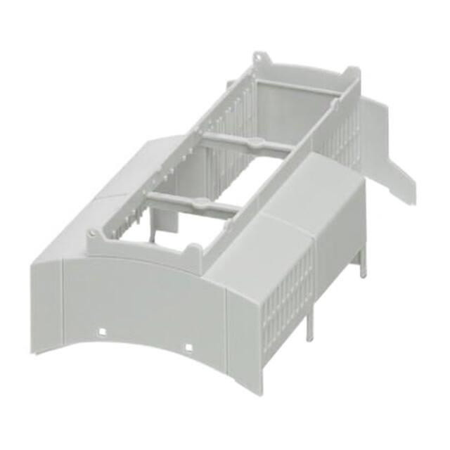
Figure 1
Overview
9.1 Circuit diagram of DIN rail connector ................. 45
9.2 Dimensional drawing of connector for DIN rail
connector .......................................................... 45
102981_en_05
PHOENIX CONTACT
2
�BC... installation component housing
Overview of BC Products
BC 17,8…
BC 71,6…
BC 53,6…
BC 35,6…
(1TE)
(4TE)
(3TE)
(2TE)
HBUS 53,6…3S…
HBUS 35,6…2S…
HBUS 71,6…1S…
HBUS 53,6…1S… BC 161,6…
HBUS 35,6…1S…
(9TE)
BC 107,6…
(6TE)
HBUS 161,6…1S…
HBUS 107,6…1S…
Figure 2
102981_en_05
Overview of design widths with corresponding DIN rail connector HBUS
PHOENIX CONTACT
3
�BC... installation component housing
Ordering data
3
Ordering data
3.1
Ordering data (1TE to 9TE)
Design width 17.8 mm (1TE)
Description
Type
Order No.
Pcs. / Pkt.
Lower housing part
BC 17,8 UT HBUS BK
2896241
10
Upper housing part, for horizontal PCB connection with 3.5 mm or 5 mm
pitch
BC 17,8 OTU MKDSO KMGY
2279732
10
Housing cover, permanently snapped onto the upper housing part, in the
same light gray color as the housing
BC 17,8 DKL R KMGY
2896144
10
Housing cover, hinged, can be sealed, transparent, including fitted cover
BC 17,8 DKL S TRANS
2896102
10
Left MKDSO 1,5/ 4-L-3,5 KMGY
2278432
50
Right MKDSO 1,5/ 4-R-3,5 KMGY
2278429
50
Left MKDSO 2,5/3-L KMGY
2854102
50
Right MKDSO 2,5/3-R KMGY
2854092
50
2 Slots HBUS 35,6-16P-2S BK
2896319
10
3 Slots HBUS 53,6-16P-3S BK
Accessories
PCB terminal block, for soldering onto PCB,
3.5 mm pitch, number of positions: 4
PCB terminal block, for soldering onto PCB, 5 mm pitch,
number of positions: 3
DIN rail connector, 16-pos., 18-pos. slots to the PCB
Power plug for DIN rail connector, with 16 free cable ends
with a cross section of 0.25 mm², 500 mm long
2896322
10
Socket strip BL2-2,54/16-ST
2896335
50
Pin strip SL2-2,54/16-ST
2896348
50
Cover cap set, 3-piece, for protecting empty DIN rail connectors
HBUS-B SET BK
2278173
10
Filler plug for empty terminal space
ME 17,5 OTU-MKDSO KMGY
2854115
50
Design width 35.6 mm (2TE)
Description
Type
Order No.
Pcs. / Pkt.
Lower housing part
BC 35,6 UT HBUS BK
2896254
10
Upper housing part, with vents, terminal installation depth 11.1 mm
BC 35,6 OT U11 KMGY
2896034
10
Upper housing part, with vents, terminal installation depth 22.35 mm
BC 35,6 OT U22 KMGY
2896047
10
Housing cover, permanently snapped onto the upper housing part, in the
same light gray color as the housing
BC 35,6 DKL R KMGY
2896157
10
Housing cover, hinged, can be sealed, transparent, including fitted cover
BC 35,6 DKL S TRANS
2896115
10
Accessories
DIN rail connector, 16-pos., 18-pos. slot to the PCB
Power plug for DIN rail connector, with 16 free cable ends
with a cross section of 0.25 mm², 500 mm long
2896283
10
Socket strip BL2-2,54/16-ST
1 Slot HBUS 35,6-16P-1S BK
2896335
50
Pin strip SL2-2,54/16-ST
2896348
50
2278173
10
Cover cap set, 3-piece, for protecting empty DIN rail connectors
HBUS-B SET BK
Filler plug for empty terminal space, 17.6 mm design
width, for terminal installation depth
11 mm BC 17,6 BS U11 KMGY
2896186
50
22 mm BC 17,6 BS U22 KMGY
2896199
50
Filler plug for empty terminal space, 35.6 mm design
width, for terminal installation depth
11 mm BC 35,6 BS U11 KMGY
2896209
50
22 mm BC 35,6 BS U22 KMGY
2896212
50
102981_en_05
PHOENIX CONTACT
4
�BC... installation component housing
Ordering data
Design width 53.6 mm (3TE)
Description
Type
Order No.
Pcs. / Pkt.
Lower housing part
BC 53,6 UT HBUS BK
2896403
10
Upper housing part, with vents, terminal installation depth 11.1 mm
BC 53,6 OT U11 KMGY
2896416
10
Upper housing part, with vents, terminal installation depth 22.35 mm
BC 53,6 OT U22 KMGY
2896429
10
Housing cover, permanently snapped onto the upper housing part, in the
same light gray color as the housing
BC 53,6 DKL R KMGY
2896432
10
Housing cover, hinged, can be sealed, transparent, including fitted cover
BC 53,6 DKL S TRANS
2896445
10
Accessories
DIN rail connector, 16-pos., 18-pos. slot to the PCB
Power plug for DIN rail connector, with 16 free cable ends
with a cross section of 0.25 mm², 500 mm long
2896458
10
Socket strip BL2-2,54/16-ST
1 Slot HBUS 53,6-16P-1S BK
2896335
50
Pin strip SL2-2,54/16-ST
2896348
50
2278173
10
Cover cap set, 3-piece, for protecting empty DIN rail connectors
HBUS-B SET BK
Filler plug for empty terminal space, 17.6 mm design
width, for terminal installation depth
11 mm BC 17,6 BS U11 KMGY
2896186
50
22 mm BC 17,6 BS U22 KMGY
2896199
50
Filler plug for empty terminal space, 35.6 mm design
width, for terminal installation depth
11 mm BC 35,6 BS U11 KMGY
2896209
50
22 mm BC 35,6 BS U22 KMGY
2896212
50
Filler plug for empty terminal space, 53.6 mm design
width, for terminal installation depth
11 mm BC 53,6 BS U11 KMGY
2896225
50
22 mm BC 53,6 BS U22 KMGY
2896238
50
Design width 71.6 mm (4TE)
Description
Type
Order No.
Pcs. / Pkt.
Lower housing part
BC 71,6 UT HBUS BK
2896267
10
Upper housing part, with vents, terminal installation depth 11.1 mm
BC 71,6 OT U11 KMGY
2896050
10
Upper housing part, with vents, terminal installation depth 22.35 mm
BC 71,6 OT U22 KMGY
2896063
10
Housing cover, permanently snapped onto the upper housing part, in the
same light gray color as the housing
BC 71,6 DKL R KMGY
2896160
10
Housing cover, hinged, can be sealed, transparent, including fitted cover
BC 71,6 DKL S TRANS
2896128
10
Accessories
DIN rail connector, 16-pos., 18-pos. slot to the PCB
Power plug for DIN rail connector, with 16 free cable ends
with a cross section of 0.25 mm², 500 mm long
2896296
10
Socket strip BL2-2,54/16-ST
1 Slot HBUS 71,6-16P-1S BK
2896335
50
Pin strip SL2-2,54/16-ST
2896348
50
2278173
10
Cover cap set, 3-piece, for protecting empty DIN rail connectors
HBUS-B SET BK
Filler plug for empty terminal space, 17.6 mm design
width, for terminal installation depth
11 mm BC 17,6 BS U11 KMGY
2896186
50
22 mm BC 17,6 BS U22 KMGY
2896199
50
Filler plug for empty terminal space, 35.6 mm design
width, for terminal installation depth
11 mm BC 35,6 BS U11 KMGY
2896209
50
22 mm BC 35,6 BS U22 KMGY
2896212
50
102981_en_05
PHOENIX CONTACT
5
�BC... installation component housing
Ordering data
Design width 107.6 mm (6TE)
Description
Type
Order No.
Pcs. / Pkt.
Lower housing part
BC 107,6 UT HBUS BK
2896270
10
Upper housing part, with vents, terminal installation depth 11.1 mm
BC 107,6 OT U11 KMGY
2896076
10
Upper housing part, with vents, terminal installation depth 22.35 mm
BC 107,6 OT U22 KMGY
2896089
10
Housing cover, permanently snapped onto the upper housing part, in the
same light gray color as the housing
BC 107,6 DKL R KMGY
2896173
10
Housing cover, hinged, can be sealed, transparent, including fitted cover
BC 107,6 DKL S TRANS
2896131
10
Accessories
DIN rail connector, 16-pos., 18-pos. slot to the PCB
Power plug for DIN rail connector, with 16 free cable ends
with a cross section of 0.25 mm², 500 mm long
2896306
10
Socket strip BL2-2,54/16-ST
1 Slot HBUS 107,6-16P-1S BK
2896335
50
Pin strip SL2-2,54/16-ST
2896348
50
2278173
10
Cover cap set, 3-piece, for protecting empty DIN rail connectors
HBUS-B SET BK
Filler plug for empty terminal space, 17.6 mm design
width, for terminal installation depth
11 mm BC 17,6 BS U11 KMGY
2896186
50
22 mm BC 17,6 BS U22 KMGY
2896199
50
Filler plug for empty terminal space, 35.6 mm design
width, for terminal installation depth
11 mm BC 35,6 BS U11 KMGY
2896209
50
22 mm BC 35,6 BS U22 KMGY
2896212
50
Filler plug for empty terminal space, 53.6 mm design
width, for terminal installation depth
11 mm BC 53,6 BS U11 KMGY
2896225
50
22 mm BC 53,6 BS U22 KMGY
2896238
50
Design width 161.6 mm (9TE)
Description
Type
Order No.
Pcs. / Pkt.
Lower housing part
BC 161,6 UT HBUS BK
2278500
10
Upper housing part, with vents, terminal installation depth 11.1 mm
BC 161,6 OT U11 KMGY
2278513
10
Upper housing part, with vents, terminal installation depth 22.35 mm
BC 161,6 OT U22 KMGY
2278526
10
Housing cover, permanently snapped onto the upper housing part, in the
same light gray color as the housing
BC 161,6 DKL R KMGY
2278539
10
Housing cover, hinged, can be sealed, transparent, including fitted cover
BC 161,6 DKL S TRANS
2278542
10
Accessories
DIN rail connector, 16-pos., 18-pos. slot to the PCB
Power plug for DIN rail connector, with 16 free cable ends
with a cross section of 0.25 mm², 500 mm long
2278555
10
Socket strip BL2-2,54/16-ST
1 Slot HBUS 161,6-16P-1S BK
2896335
50
Pin strip SL2-2,54/16-ST
2896348
50
2278173
10
Cover cap set, 3-piece, for protecting empty DIN rail connectors
HBUS-B SET BK
Filler plug for empty terminal space, 17.6 mm design
width, for terminal installation depth
11 mm BC 17,6 BS U11 KMGY
2896186
50
22 mm BC 17,6 BS U22 KMGY
2896199
50
Filler plug for empty terminal space, 35.6 mm design
width, for terminal installation depth
11 mm BC 35,6 BS U11 KMGY
2896209
50
22 mm BC 35,6 BS U22 KMGY
2896212
50
Filler plug for empty terminal space, 53.6 mm design
width, for terminal installation depth
11 mm BC 53,6 BS U11 KMGY
2896225
50
22 mm BC 53,6 BS U22 KMGY
2896238
50
102981_en_05
PHOENIX CONTACT
6
�BC... installation component housing
Ordering data
3.2
Order key for BC 161,6 modular – upper part
With BC 161,6 modular, the side panel for each segment on
each side of the housing can be arranged in three different
positions.
– When the side panel is located at the innermost position, the installation space for connection technology is
maximized to 22 mm (see Figure 3, pos. 1 and 2).
– In the middle side panel position there is 11 mm of
space on the outside for the connection technology
(see Figure 3, pos. 3 and 4).
– The maximum mounting surface for the PCB is available when the side panel of the upper housing part is
flush with the outside edge of the lower housing part
(see Figure 3, pos. 5 and 6)
Ordering data for example configurations
Ordering data for upper part of BC 161,6 modular
Description
Type
Order No.
Pcs. /
Pkt.
Upper housing part, with
vents,
1 x terminal installation depth of
22 mm at pos. 5, all other terminal spaces closed
BC 161,6 OT
000020 KMGY
2201450
10
Upper housing part, with
vents,
1 x terminal installation depth of
22 mm at pos. 3, all other terminal spaces closed
BC 161,6 OT
002000 KMGY
2201451
10
Upper housing part, with
vents,
2 x terminal installation depth of
22 mm at pos. 5 and 6, all other
terminal spaces closed
BC 161,6 OT
000022 KMGY
2201454
10
The corresponding lower housing part and the accessories
can be found in the ordering data for design width 161.6 mm
(9TE) (see page 6).
Figure 3
xxxxxxx
No. is assigned by
Phoenix
Contact
after receipt
of the order
Positions for order key
Location
/ BC 161,6 OT / 1 / 2 / 3 / 4 / 5 / 6 /KMGY
Side panel
Housing
color: light
0 = outside
gray
1 = middle
2 = inside
Example for Figure 3:
BC 161,6 OT 221100 KMGY
Side panel
– Locations 1 and 2: inside
– Locations 3 and 4: middle
– Locations 5 and 6: outside
102981_en_05
PHOENIX CONTACT
7
�BC... installation component housing
Ordering data
3.3
Selecting the right connection technology
Module
BC
17,8
BC 35,6
U11
U22
BC 53,6
U11
U22
BC 71,6
U11
U22
BC 107,6
U11
U22
BC 161,6
U11
U22
MKDSO 1,5/4-L-3,5
X
–
–
–
–
–
–
–
–
–
–
MKDSO 1,5/4-R-3,5
X
–
–
–
–
–
–
–
–
–
–
MKDSO 2,5/3-L
X
–
–
–
–
–
–
–
–
–
–
MKDSO 2,5/3-R
X
–
–
–
–
–
–
–
–
–
–
X
MKDS 1,5/... HT
–
X
X
X
X
X
X
X
X
X
MKDSN 2,5/... HT
–
X
X
X
X
X
X
X
X
X
X
MKDS 3/... HT
–
X
X
X
X
X
X
X
X
X
X
MKDS 1,5/...
–
X
X
X
X
X
X
X
X
X
X
MKDSP 1,5/…
–
X
X
X
X
X
X
X
X
X
X
MKDSN 2,5/...
–
X
X
X
X
X
X
X
X
X
X
MKDS 3/...
–
X
X
X
X
X
X
X
X
X
X
MKDSP 3/…
–
X
X
X
X
X
X
X
X
X
X
MKKDSH 3/…
–
X
X
X
X
X
X
X
X
X
X
GMKDS 1,5/…
–
X
X
X
X
X
X
X
X
X
X
GMKDS 3/…
–
X
X
X
X
X
X
X
X
X
X
GMKDSP 3/…
–
X
X
X
X
X
X
X
X
X
X
SPTA 1/...-3,5
–
X
X
X
X
X
X
X
X
X
X
SPTA 1/...-5,0
–
X
X
X
X
X
X
X
X
X
X
MKKDS 1,5/…
–
–
X
–
X
–
X
–
X
–
X
MKKDS 3/…
–
–
X
–
X
–
X
–
X
–
X
MKKDSG 3/…
–
–
X
–
X
–
X
–
X
–
X
ZFKKDS 1,5C-5,0
–
–
X
–
X
–
X
–
X
–
X
FK-MPT 0,5/...-3,5-H
–
X
X
X
X
X
X
X
X
X
X
FK-MPT 0,5/…ST-3,5
–
X
X
X
X
X
X
X
X
X
X
PTSA 0,5/...-2,5-Z
–
X
X
X
X
X
X
X
X
X
X
PTSA 0,5/...-2,5-F
–
X
X
X
X
X
X
X
X
X
X
PTSA 1,5/...-3,5-Z
–
X
X
X
X
X
X
X
X
X
X
PTSA 1,5/...-3,5-F
–
X
X
X
X
X
X
X
X
X
X
PTS 1,5/...-5,0-H
–
X
X
X
X
X
X
X
X
X
X
PT 1,5/...-5,0-H
–
X
X
X
X
X
X
X
X
X
X
PT 1,5/...-PH-5,0
–
X
X
X
X
X
X
X
X
X
X
PT 1,5/...-5,0-H
–
X
X
X
–
X
X
X
X
X
X
PT 2,5/4-7,5-H
–
X
X
X
X
X
X
X
X
X
X
PTDA 1,5/...-PH-3,5
–
–
X
–
X
–
X
–
X
–
X
PTDA 1,5/...-PH-5,0
–
–
X
–
X
–
X
–
X
–
X
PT 2,5/...-PVH-5,0
–
–
X
–
X
–
X
–
X
–
X
PST 1,3/...-LH-5,0
–
–
X
–
X
–
X
–
X
–
X
PST 1,3/...-LV-5,0
–
–
X
–
X
–
X
–
X
–
X
PST 1,0/...-3,5
–
X
X
X
X
X
X
X
X
X
X
PST 1,3/...-5,0
–
X
X
X
X
X
X
X
X
X
X
VS-08-BU-RJ45…
–
–
X
–
X
–
X
–
X
–
X
102981_en_05
PHOENIX CONTACT
8
�BC... installation component housing
Technical data
4
Technical data
Electrical data
Power dissipation PV at 20°C in the horizontal mounting position, aligned without distance
BC 17,8
2.95 W
BC 35,6
4.78 W
BC 53,6
7.21 W
BC 71,6
11.95 W
BC 107,6
13.08 W
BC 161,6
16.95 W
DIN rail connector HBUS
60 V
DIN rail connector HBUS, current carrying capacity for each contact
3 A, maximum total current 25 A
Housing version
Insulation material
Polycarbonate
Inflammability class according to UL 94
V0
Color of lower housing part
Black
Color of upper housing part
Light gray
102981_en_05
PHOENIX CONTACT
9
�BC... installation component housing
Housing dimensions
5
Housing dimensions
5.1
Dimensions of housing
89,7
62,2
Figure 4
89,7
22,35
11,1
22,35
62,2
11,1
BC...U11, side view
Figure 5
BC...U22, side view
Exterior dimensions, front view
0
17,5 +0,5
0
36-0,5
0
0
54 -0,5
BC 17,8 ... BC 35,6 ... BC 53,6 ...
0
0
72 -0,5
108 -0,5
162 -0,5
BC 71,6 ...
BC 107,6 ...
BC 161,6 ...
Interior dimensions, top view
15,1
Figure 6
32
50
32
32
50
50
50
50
50
Exterior and interior dimensions
Dimensions and tolerances acc. to DIN 43880
102981_en_05
PHOENIX CONTACT
10
�BC... installation component housing
Housing dimensions
5.2
Dimensions of DIN rail connector
a
6
4,7
3,2
7,6
1
1
EN 50022, NS 35 x 7,5
Figure 7
Dimensions of DIN rail connector HBUS and DIN rail NS 35
Dimensions for a
HBUS 35,6-16P-1S BK
HBUS 35,6-16P-2S BK
HBUS 53,6-16P-1S BK
HBUS 53,6-16P-3S BK
HBUS 71,6-16P-1S BK
HBUS 161,6-16P-1S BK
102981_en_05
37,1
35.6 mm
35.6 mm
53.6 mm
53.6 mm
71.6 mm
161.6 mm
PHOENIX CONTACT
11
�BC... installation component housing
PCB arrangement for BC 17,8 (1TE)
6
PCB arrangement for BC 17,8 (1TE)
6.1
PCB dimensions
62,4
57,6
42,3
5
6,9
5
10
3,35
5,55
23,05
37,5
18,15
42,05
35,65
51
43,8
10
38,4
28,8
47,6
84,3
Figure 8
Upper side – mounting side of BC 17,8
PCB thickness
102981_en_05
Maximum 1.5 mm
Locked area, no components at
these positions
PHOENIX CONTACT
12
�BC... installation component housing
PCB arrangement for BC 17,8 (1TE)
3 0°
A
MKDSO 2,5/3 R
0,5
MKDSO 2,5/3 L
R
1,
2
R
1,
1,2
2 R
R
°
2
1,
Lower side – soldering side of BC 17,8
A
PCB thickness
102981_en_05
45
2
R
1,
Figure 9
PCB surface, when no fitted
cover is used
Maximum 1.5 mm
Locked area, no components at
these positions
PHOENIX CONTACT
13
�BC... installation component housing
PCB arrangement for BC 17,8 (1TE)
6.2
Inner dimensions
1,5
11,08
2,53
Figure 10
102981_en_05
Inner dimensions BC 17,8
PHOENIX CONTACT
14
�BC... installation component housing
PCB arrangement for BC 17,8 (1TE)
6.4
Circuit diagram of DIN rail connector with
2 and 3 slots
6
8
10
3
5
7
9
12 11
14 13
16 15
Figure 11
2
1
4
3
6
5
8
10
7
9
12 11
14 13
16 15
Figure 12
2 1
2 1
4 3
4 3
5 6
5 6
7 8
7 8
10 9
10 9
12 11
12 11
14 13
14 13
15a15b
15a15b
16a16b
16a16b
1
2
3
4
5
6
7
8
9
10
max. 1,8
11 12
13 14
15 16
A
Circuit diagram HBUS 35,6-16P-2S BK
2 1
2 1
2 1
4 3
4 3
4 3
5 6
5 6
5 6
7 8
7 8
7 8
10 9
10 9
10 9
12 11
12 11
12 11
14 13
14 13
14 13
15a15b
15a15b
15a15b
16a16b
16a16b
16a16b
1
2
3
4
5
6
7
8
9
10
Figure 13
A
11 12
13 14
±0,3
4
1
1,31
2,1
2
Dimensional drawing of connector for DIN rail
connector
min. 6,8
6.3
Dimensional drawing of connector on perpendicular PCB (in BC 17,8) for contacting in the
DIN rail connector
Pin strip, max. 2 x 9-pos.
□ 0.63 x 0.63 mm or ø 0.7 – 0.8 mm
2.54 mm pitch
Gold-plated surface
15 16
Circuit diagram for HBUS 53,6-16P-3S BK
Contacts
Contact 1 ... 4
Contact 5 ... 16
Power
Signal
Air and creepage distances
... to the DIN rail
... between one another
... between power and signal
min. 0.23 mm
min. 0.13 mm
min. 0.8 mm
Current carrying capacity for each contact
3 A, maximum total current 25 A
102981_en_05
PHOENIX CONTACT
15
�BC... installation component housing
PCB arrangement for BC 2TE – 9TE
7
PCB arrangement for BC 2TE – 9TE
7.1
Plug-in positions for horizontal PCBs
PCB 9
PCB 8
PCB 7
30,45
27,6
26,3
23,75
3,55
PCB 4
18,7
8,6
PCB 5
13,65
PCB 6
PCB 3
PCB 2
PCB 1
Figure 14
Overview of the PCB plug-in positions
PCB thickness
PCB 1
PCB 2 – 8
PCB 9
1.5 mm ... 1.8 mm
Maximum 1.8 mm
Maximum 1.8 mm
A circuit board at PCB 9 is only possible when a fitted cover
is not used. The fitted cover is supplied as standard with the
transparent cover.
102981_en_05
PHOENIX CONTACT
16
�BC... installation component housing
PCB arrangement for BC 2TE – 9TE
7.2
Circuit board dimensions for PCB 1, horizontal
Circuit board dimensions for PCB 1, horizontal (BC 35,6...)
An overview of the arrangement of the horizontal circuit
boards PCB 1 – 9 can be found on page 16.
31,7
15,8
1,
2,2
2
1,5
1,5
0,93
4,9
1,63
R
1,
2
5,3
2,43
13,1
0,75
27,4
18,2
1,25
R
0,95
A
3,88
1,5
1,6
45
67,5
86,4
1,6
20,32
15,24
10,16
5,08
42
0,8
2,54
BC 35,6 OT-U22
BC 35,6 OT-U11
Upper side
Figure 15
Dimensions of PCB 1 (BC 35,6)
A
PCB thickness
102981_en_05
Lower side
Contour for filler plug
Maximum 1.8 mm
Locked area, no components at
these positions
PHOENIX CONTACT
17
�BC... installation component housing
PCB arrangement for BC 2TE – 9TE
Circuit board dimensions for PCB 1, horizontal (BC 53,6...)
An overview of the arrangement of the horizontal circuit
boards PCB 1 – 9 can be found on page 16.
2,2
1,5
1,5
R
1,
4,9
5,3
4,9
0,93
0,75
1,25
2,43
1,2
A
45,4
18,2
0,95
R
49,7
33,8
31,1
12,7
2
3,88
BC 53,6 OT-U22
1,6
45
67,5
86,4
1,5
1,6
42
20,32
15,24
10,16
5,08
0,8
2,54
Upper side
Lower side
BC 53,6 OT-U11
Figure 16
Dimensions of PCB 1 (BC 53,6)
A
PCB thickness
102981_en_05
Contour for filler plug
Maximum 1.8 mm
Locked area, no components at
these positions
PHOENIX CONTACT
18
�BC... installation component housing
PCB arrangement for BC 2TE – 9TE
Circuit board dimensions for PCB 1, horizontal (BC 71,6...)
67,7
51,8
49,1
30,7
15,8
A
R
1,
2
2,2
0,95
An overview of the arrangement of the horizontal circuit
boards PCB 1 – 9 can be found on page 16.
5,3
4,9
2,54
1,1
2,4
1,9
R
BC 71,6 OT-U22
1,
2
10,7
R
1,
2
3,88
0,8
45
67,5
1,6
20,32
15,24
10,16
5,08
86,4
42
R
1,
2
4,9
2,43
5,3
0,75
0,93
13,1
4,3
BC 71,6 OT-U11
Figure 17
Dimensions of PCB 1 (BC 71,6) – upper side
A
PCB thickness
102981_en_05
Contour for filler plug
Maximum 1.8 mm
Locked area, no components at
these positions
PHOENIX CONTACT
19
�BC... installation component housing
PCB arrangement for BC 2TE – 9TE
1,5
1,63
1,5
1,6
1,25
63,4
18,2
4,3
1,5
Figure 18
Dimensions of PCB 1 (BC 71,6) – lower side
PCB thickness
102981_en_05
Maximum 1.8 mm
Locked area, no components at
these positions
PHOENIX CONTACT
20
�BC... installation component housing
PCB arrangement for BC 2TE – 9TE
Circuit board dimensions for PCB 1, horizontal (BC 107,6...)
An overview of the arrangement of the horizontal circuit
boards PCB 1 – 9 can be found on page 16.
87,8
85,1
66,7
A
51,8
49,1
30,7
15,8
2,2
1,
2
0,95
R
5,3
5,3
4,9
5,3
4,9
3,88
0,8
2,54
R
BC 107,6 OT-U22
1,1
2
1,
1,9
4,3
Dimensions of PCB 1 (BC 107,6) – upper side
A
PCB thickness
102981_en_05
R
2
1,
2,4
10,7
BC 107,6 OT-U11
Figure 19
45
67,5
1,6
15,24
10,16
5,08
20,32
42
86,4
R
1,
2
4,9
2,43
0,75
0,93
13,1
Contour for filler plug
Maximum 1.8 mm
Locked area, no components at
these positions
PHOENIX CONTACT
21
�BC... installation component housing
PCB arrangement for BC 2TE – 9TE
103,7
99,4
18,2
4,3
1,5
1,5
1,6
1,25
1,63
1,5
Figure 20
Dimensions of PCB 1 (BC 107,6) – lower side
PCB thickness
102981_en_05
Maximum 1.8 mm
Locked area, no components at
these positions
PHOENIX CONTACT
22
�BC... installation component housing
PCB arrangement for BC 2TE – 9TE
Circuit board dimensions for PCB 1, horizontal (BC 161,6...)
An overview of the arrangement of the horizontal circuit
boards PCB 1 – 9 can be found on page 16.
141,8
105,8
69,8
33,8
R
1,2
0,95
2,2
1,6
2,54
4,9
5,3
4,9
5,3
4,9
5,3
4,9
5,3
4,9
2,43
BC 161,6 OT-U22
0,93
3,88
0,8
45
67,5
5,08
15,24
10,16
42
20,32
86,4
156,2
12,7
BC 161,6 OT-U11
31,7
48,7
67,1
84,7
103,1
120,7
139,1
Figure 21
Dimensions of PCB 1 (BC 161,6) – upper side
PCB thickness
102981_en_05
Maximum 1.8 mm
Locked area, no components at
these positions
PHOENIX CONTACT
23
�BC... installation component housing
PCB arrangement for BC 2TE – 9TE
153,4
126,2
109,5
93,07
18,2
1,51
1,63
1,25
1,5
1,25
1,63
1,63
1,5
1,25
1,51
1,5
1,6
1,5
2,4
2
1,
4,3
R
1,1
10,7
1,2
R
54
157,5
Figure 22
Dimensions of PCB 1 (BC 161,6) – lower side
PCB thickness
102981_en_05
Maximum 1.8 mm
Locked area, no components at
these positions
PHOENIX CONTACT
24
�BC... installation component housing
PCB arrangement for BC 2TE – 9TE
7.3
Circuit board dimensions for PCB 2 to 8, horizontal
62,3
39,8
35,7
An overview of the arrangement of the horizontal circuit
boards PCB 1 – 9 can be found on page 16.
1,5
3,9
R 1,2
0,95
1,25
24,9
Figure 27
Dimensions of PCB 6
a
50,8
39,8
24,9
39,8 (U11)
62,3 (U22)
Figure 28
Dimensions of PCB 7
Dimensions of PCB 2
39,8
1,25
Figure 23
30,8
28,4
R
1,
2
a
0,95
62,3
39,8
35,7
Figure 24
Dimensions of PCB 3
62,3
Figure 29
Dimensions of PCB 8
39,8
28,5
Figure 25
Dimensions of PCB 4
62,3
Dimensions for a
BC 35,6 UT 30.3
BC 53,6 UT 48.3
BC 71,6 UT 66.3
BC 71,6 UT 102.3
BC 161,6 UT 156.3
PCB thickness
Maximum 1.8 mm
39,8
32,1
Figure 26
102981_en_05
Dimensions of PCB 5
PHOENIX CONTACT
25
�BC... installation component housing
PCB arrangement for BC 2TE – 9TE
7.4
Circuit board dimensions for PCB 9, horizontal
An overview of the arrangement of the horizontal circuit
boards PCB 1 – 9 can be found on page 16.
A circuit board at PCB 9 is only possible when a fitted cover
is not used. The fitted cover is supplied as standard with the
transparent cover.
22,8
24,85
32,2
Circuit board dimensions for PCB 9, horizontal (BC 35,6...)
Upper side
Figure 30
Lower side
Dimensions of PCB 9 (BC 35,6)
Upper side
Figure 31
4,8
Lower side
Dimensions of PCB 9 (BC 53,6)
PCB thickness
102981_en_05
23,2
40,8
42,85
50,2
Circuit board dimensions for PCB 9, horizontal (BC
53,6...)
Maximum 1.8 mm
Locked area, no components at
these positions
PHOENIX CONTACT
26
�BC... installation component housing
PCB arrangement for BC 2TE – 9TE
Circuit board dimensions for PCB 9, horizontal (BC 71,6...)
An overview of the arrangement of the horizontal circuit
boards PCB 1 – 9 can be found on page 16.
0,9
0,6
Figure 32
ø7
5,2
22,8
3
Lower side
Dimensions of PCB 9 (BC 71,6)
PCB thickness
102981_en_05
0,65
Upper side
41,2
58,8
7,25
60,85
68,2
1,95
4
1,95
41,7
Maximum 1.8 mm
Locked area, no components at
these positions
PHOENIX CONTACT
27
�BC... installation component housing
PCB arrangement for BC 2TE – 9TE
Circuit board dimensions for PCB 9, horizontal (BC 107,6...)
Upper side
Figure 33
Lower side
Dimensions of PCB 9 (BC 107,6)
PCB thickness
102981_en_05
77,2
94,8
96,85
104,2
An overview of the arrangement of the horizontal circuit
boards PCB 1 – 9 can be found on page 16.
Maximum 1.8 mm
Locked area, no components at
these positions
PHOENIX CONTACT
28
�BC... installation component housing
PCB arrangement for BC 2TE – 9TE
Circuit board dimensions for PCB 9, horizontal (BC 161,6...)
Upper side
Figure 34
59,2
76,8
95,2
112,8
54
Lower side
Dimensions of PCB 9 (BC 161,6)
PCB thickness
102981_en_05
131,2
148,8
42,85
61,25
150,85
An overview of the arrangement of the horizontal circuit
boards PCB 1 – 9 can be found on page 16.
Maximum 1.8 mm
Locked area, no components at
these positions
PHOENIX CONTACT
29
�BC... installation component housing
PCB arrangement for BC 2TE – 9TE
7.5
Perpendicular PCBs – transverse to the DIN rail
BC...U11
38,4
R
A
A
38,4
1,65
30°
R
2
1,
64,2
Figure 35
39
30,05
39
31,8
31
0,75
41,7
0,75
Dimensions of BC...U11
PCB thickness
A
30,05
1,2
R
0°
10
26,4
25,5
6
6
2
1,
30°
BC...U22
Figure 36
Dimensions of BC...U22
Maximum 1.8 mm
Locked area, no components at
these positions
PCB surface, when no fitted cover
is used
1,85
2,23
11,03
20,23
29,03
Figure 37
102981_en_05
Cross-sectional view - perpendicular PCBs
PHOENIX CONTACT
30
�BC... installation component housing
PCB arrangement for BC 2TE – 9TE
7.6
Perpendicular PCBs – parallel to the DIN rail
24,9
A
7,3
0,55
R
1,5
30
39
3,9
4,9
21,25
1,5
1,2
1,25
Figure 39
Figure 38
Perpendicular PCBs arranged parallel to the
DIN rail
a
Dimensions for perpendicular PCBs
Dimensions for a
BC 35,6 UT 30.3
BC 53,6 UT 48.3
BC 71,6 UT 66.3
BC 71,6 UT 102.3
BC 161,6 UT 156.3
PCB thickness
A
102981_en_05
0,95
Maximum 1.8 mm
Locked area, no components at
these positions
PCB surface, when no fitted cover
is used
PHOENIX CONTACT
31
�BC... installation component housing
PCB arrangement for BC 161,6 modular
8
PCB arrangement for BC 161,6 modular
8.1
Plug-in positions for horizontal PCBs
PCB 9
30,46
27,61
26,3
23,75
PCB 2
3,55
PCB 1
PCB 4
18,7
PCB 3
PCB 6
13,65
PCB 5
PCB 8
8,6
PCB 7
Figure 40
Overview of the plug-in positions for horizontal PCBs
PCB thickness
PCB 1
PCB 2 – 8
PCB 9
102981_en_05
Maximum 1.8 mm
Maximum 1.8 mm
Maximum 1.8 mm
PHOENIX CONTACT
32
�BC... installation component housing
PCB arrangement for BC 161,6 modular
8.2
Versions for the terminal installation space
0
1
2
Figure 41
Version
0
1
2
102981_en_05
Terminal installation depth 0, 1 and 2
Terminal installation
depth
0 mm
11 mm
22 mm
PHOENIX CONTACT
33
�BC... installation component housing
PCB arrangement for BC 161,6 modular
8.3
Circuit board dimensions for PCB 1, horizontal
An overview of the arrangement of the horizontal circuit
boards PCB 1 – 9 can be found on page 32.
48,7
31
12,7
1,1
1,25
0,75
3,9
48,7
1,6
5,3
4,9
0,95
Figure 42
0,93
2
R1,
0,93
2,43
26,1
2,43
33,75
3,9
12,7
4,9
24,35
45
27,15
31,1
86,4
0,8
2,2
33,8
A
Upper side – mounting side of BC modular 161,6 (example BC 161,6 OT 010122)
A
PCB thickness
Contour for filler plug
Maximum 1.8 mm
Locked area, no components at
these positions
Surface of the main PCB approx. 13000 mm² (mounting
side)
102981_en_05
PHOENIX CONTACT
34
�BC... installation component housing
PCB arrangement for BC 161,6 modular
54
24,4
2,3
4,3
R1
,2
2,54
3,88
1,1
10,7
,2
R1
5,08
10,16
1,6
156,2
2,4
20,32
15,24
1,5
42
R1
,2
0,3
R1
,2
1,5
,2
R1
4,3
1,63
18,11
1,5
49,7
54
108
157,7
Figure 43
Lower side – soldering side of BC modular 161,6 (example BC 161,6 OT 010122)
PCB thickness
102981_en_05
Maximum 1.8 mm
Locked area, no components at
these positions
PHOENIX CONTACT
35
�BC... installation component housing
PCB arrangement for BC 161,6 modular
8.4
Circuit board dimensions for PCB 2 to 8, horizontal
An overview of the arrangement of the horizontal circuit
boards PCB 1 – 9 can be found on page 32.
41,75
1,5
35,7
3,9
R1
,2
R1
,2
0,95
156,3
R1
,2
3,9
1,25
1,5
156,3
R1
,2
24,9
0,95
31,15
41,75
1,25
31,15
R1
,2
52,25
3,9
24,9
102981_en_05
1,25
R1
,2
R1
,2
3,9
1,5
35,7
39,8
Figure 44
R1
,2
51,35
0,95
R1
,2
1,25
R1
,2
0,95
52,25
51,35
R1
,2
R1
,2
Dimensions of PCB 2
(example BC 161,6 OT 010122)
1,5
39,8
Figure 45
Dimensions of PCB 3
(example BC 161,6 OT 010122)
PHOENIX CONTACT
36
�BC... installation component housing
PCB arrangement for BC 161,6 modular
1,5
3,9
R1
,2
R1
,2
0,95
R1
,2
3,9
156,3
R1
,2
41,75
32,1
52,25
R1
,2
R1
,2
51,35
R1
,2
R1
,2
0,95
R1
,2
1,25
R1
,2
0,95
51,35
52,25
R1
,2
R1
,2
3,9
3,9
28,5
32,1
1,5
102981_en_05
Dimensions of PCB 4
(example BC 161,6 OT 010122)
1,5
39,8
39,8
Figure 46
1,25
156,3
0,95
31,15
1,5
1,25
41,75
28,5
1,25
31,15
Figure 47
Dimensions of PCB 5
(example BC 161,6 OT 010122)
PHOENIX CONTACT
37
�BC... installation component housing
PCB arrangement for BC 161,6 modular
34,75
50,8
1,5
1,5
3,9
2,2
156,3
R1
,2
1,25
1,25
R1
,2
R1
,2
24,9
0,6
156,3
0,95
3,9
R1
,2
35,7
0,95
31,15
51,35
R1
,2
R1
,2
51,35
3,9
35,7
1,25
0,95
1,25
R1
,2
R1
,2
0,95
51,35
52,25
R1
,2
R1
,2
1,5
39,8
3,9
24,9
1,5
39,8
Figure 48
102981_en_05
Dimensions of PCB 6
(example BC 161,6 OT 010122)
Figure 49
Dimensions of PCB 7
(example BC 161,6 OT 010122)
PHOENIX CONTACT
38
�BC... installation component housing
PCB arrangement for BC 161,6 modular
39,8
1,25
R1
,2
R1
,2
156,3
0,95
30,8
Figure 50
102981_en_05
Dimensions of PCB 8
(example BC 161,6 OT 010122)
PHOENIX CONTACT
39
�BC... installation component housing
PCB arrangement for BC 161,6 modular
8.5
Circuit board dimensions for PCB 9, horizontal
Upper side
Figure 51
59,2
76,8
95,2
112,8
54
Lower side
Dimensions of PCB 9 (BC 161,6)
PCB thickness
102981_en_05
131,2
148,8
42,85
61,25
150,85
An overview of the arrangement of the horizontal circuit
boards PCB 1 – 9 can be found on page 32.
Maximum 1.8 mm
Locked area, no components at
these positions
PHOENIX CONTACT
40
�BC... installation component housing
PCB arrangement for BC 161,6 modular
8.6
Perpendicular PCBs (BC 161,6 modular)
PCBs transverse to the DIN rail
0
1
2
Figure 52
Version
0
1
2
102981_en_05
Terminal installation depth 0, 1 and 2 (example BC 161,6 OT 010122)
Terminal installation
depth
0 mm
11 mm
22 mm
PHOENIX CONTACT
41
�BC... installation component housing
PCB arrangement for BC 161,6 modular
Dimensions for perpendicular PCBs transverse to the DIN rail
An overview of the arrangement of the perpendicular circuit
boards that are arranged transverse to the DIN rail can be
found on page 41.
43,2
20,85
9,6
6
A
7,2
19,2
21,9
22,76
30,05
39
,2
R1
30°
R12
8
,2
R1
1,4
Figure 53
Terminal installation depth 0 mm
PCB thickness
A
102981_en_05
Maximum 1.8 mm
Locked area, no components at
these positions
PCB surface, when no fitted cover
is used
PHOENIX CONTACT
42
�BC... installation component housing
PCB arrangement for BC 161,6 modular
32,1
20,85
19,2
A
6
9,7
30°
,2
R1
,2
R1
30,05
0°
25,5
26,4
39
10
0,5°
0,75
Figure 54
Terminal installation depth 11 mm
PCB thickness
A
102981_en_05
Maximum 1.8 mm
Locked area, no components at
these positions
PCB surface, when no fitted cover
is used
PHOENIX CONTACT
43
�BC... installation component housing
PCB arrangement for BC 161,6 modular
20,85
19,2
30°
A
31
30,05
39
31,8
,2
R1
0,5°
0,75
Figure 55
Terminal installation depth 22 mm
PCB thickness
Maximum 1.8 mm
Locked area, no components at
these positions
PCB surface, when no fitted cover
is used
A
A-A
1,85
1,85
A
1,85
6,95
6,95
6,95
25,35
25,35
25,35
42,95
42,95
42,95
A
108
Figure 56
102981_en_05
Cross-sectional view of perpendicular PCBs, transverse to the DIN rail
PHOENIX CONTACT
44
�BC... installation component housing
9
DIN rail connector with 1 slot (2TE – 9TE)
9.1
Circuit diagram of DIN rail connector
4
3
6
5
8
7
10
9
4 3
5 6
7 8
10 9
12 11
12 11
3
4
5
6
7
8
9
10
15 16
16a16b
Figure 57
A
4,63
Figure 58
13 14
15a15b
16 15
2
11 12
14 13
14 13
1
5,2 max.
2 1
1
Dimensional drawing of connector for DIN rail
connector
10+0,3
2
9.2
A
Dimensional drawing of connector on perpendicular PCB (all except for BC 17,8) for contacting in the DIN rail connector
Pin strip, max. 2 x 9-pos.
□ 0.63 x 0.63 mm or ø 0.7 – 0.8 mm
2.54 mm pitch
Gold-plated surface
Circuit diagram HBUS...-16P-1S BK
Contacts
Contact 1 ... 4
Contact 5 ... 16
Power
Signal
Air and creepage distances
... to the DIN rail
... between one another
... between power and signal
min. 0.23 mm
min. 0.13 mm
min. 0.8 mm
Current carrying capacity for each contact
3 A, maximum total current 25 A
102981_en_05
PHOENIX CONTACT GmbH & Co. KG • 32823 Blomberg • Germany
phoenixcontact.com
45
�