UCS
Universal electronics housings
Data sheet
107750_en_01
1
© PHOENIX CONTACT 2017-08-22
Description
The UCS... universal electronics housings consist of two
housing half-shells, which can be combined with side walls
in two different heights. The housing half-shells are available in four sizes and several colors.
– Four housing sizes:
125 x 87 mm
145 x 125 mm
195 x 145 mm
237 x 195 mm
– Two housing heights: 47 mm or 67 mm
– Colors: light gray (similar to RAL 7035) or deep black
(similar to RAL 9005). The fastening elements are
RAL 5018 (turquoise blue)
the adhesive domes. The housing half-shells are also available with customer-specific adhesive domes.
Complete housings are available for certain PCBs with a
form factor (e.g., ETX, ITX, DTX, EBX, EPIC). Corner inlays
with domes or adhesive domes are available for attaching
the PCB. In addition to the above PCB format, further PCBs
can be installed in the complete housings depending on the
size. The template layouts for the adhesive domes are available for download with the products.
Connection systems and display and operating elements
can be installed in the housings. We would be glad to install
the required openings for you.
The housings have special corner inlays, to which a PCB
can be attached. It is also possible to attach the PCBs with
adhesive domes. The adhesive domes are attached to the
housing half-shells. The PCB is screwed onto the adhesive
domes. This allows several PCBs to be added to the housings. We can also provide you with templates for positioning
A configurator is available for selecting the products at phoenixcontact.com, web code: #0512. You can use it to
create your housing. You will then receive 3D data, order lists, and PCB layouts.
Make sure you always use the latest documentation.
It can be downloaded at phoenixcontact.net/products.
This document is valid for the products listed in Section “Ordering data” from Page 4.
�UCS
Table of contents
1
Description..................................................................................................................................1
2
Overview of UCS products..........................................................................................................3
3
Ordering data..............................................................................................................................4
4
Technical data ............................................................................................................................6
5
Housing dimensions ...................................................................................................................7
5.1
5.2
5.3
5.4
6
Outer and inner dimensions ...........................................................................................................................7
Space for printing ...........................................................................................................................................8
Space for cutouts ...........................................................................................................................................9
PCB dimensions...........................................................................................................................................10
Mounting the housing ...............................................................................................................11
6.1
6.2
6.3
6.4
6.5
6.6
6.7
6.8
107750_en_01
Mounting PCBs ............................................................................................................................................11
Screw on the housing ...................................................................................................................................11
Inserting a height adapter .............................................................................................................................12
Attaching adhesive domes ...........................................................................................................................12
Mounting the housing on a wall ....................................................................................................................13
Snapping on the stand..................................................................................................................................13
Mounting accessories ..................................................................................................................................14
Mounting the housing on a DIN rail...............................................................................................................14
PHOENIX CONTACT
2 / 14
�UCS
2
Overview of UCS products
5
4
3
2
1
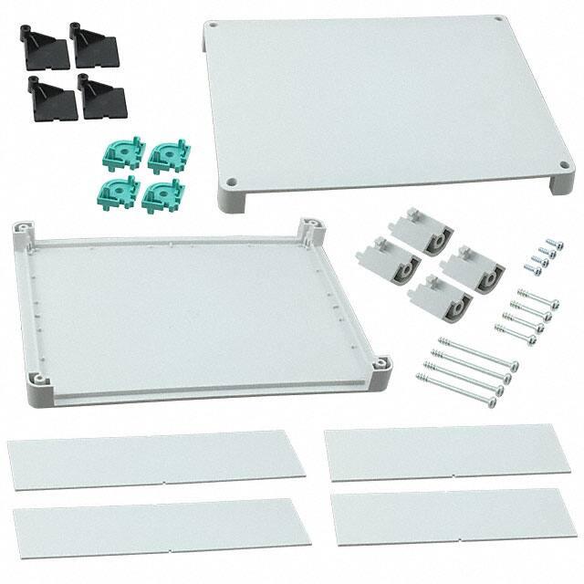
Figure 1
Overview
Accessories are available for setting up the housing.
1 Stacking adapters for connecting housings of the
same size
2 Corner guards, anti-slip
Stand for upright housings, for the 47 mm version only
3 DIN rail adapter for the following housing sizes (instead of a side panel): 125 mm x 87 mm /
145 mm x 125 mm / 195 mm x 145 mm
4 Application example with prepared side panels for various connections
5 Wall bracket, special corner inlays with longitudinal
hole for mounting on a wall
Figure 2
107750_en_01
Housing example
PHOENIX CONTACT
3 / 14
�UCS
3
Ordering data
A configurator is available for selecting the products at phoenixcontact.com, web code: #0512. You can use it to
create your housing. You will then receive 3D data, order lists, and PCB layouts.
UCS 125 x 87…
47 mm
67 mm
UCS 145 x 125…
47 mm
67 mm
UCS 195 x 145
47 mm
67 mm
UCS 237 x 195…
47 mm
67 mm
Complete housing
With PCB mounting, flexible, suitable for the following form factors*
With PCB mounting, fixed
for maximum PCB dimensions
Wall bracket
Stand
Corner guards
Stacking adapters
1
Raspberry Pi
ETX
PC/104
Pico ITX
EPIC
Nano ITX
Mini DTX
Mini ITX
EBX
Raspberry Pi
ETX
PC/104
Pico ITX
EPIC
Nano ITX
Mini DTX
Mini ITX
EBX
211.8 x 169.8 mm
169.8 x 120 mm
120 x 100 mm
100 x 62 mm
211.8 x 169.8 mm
169.8 x 120 mm
120 x 100 mm
100 x 62 mm
UCS WM-B 7035
UCS WM-B 9005
UCS WM-B 5018
UCS PED 7035
UCS PED 9005
UCS PED 5018
UCS CP 7035
UCS CP 9005
UCS CP 5018
UCS CS 7035
UCS CS 9005
RAL 70351
2203328 2203331
2203332 2203334
2203332 2203334
2203332 2203334
2203336 2203338
2203336 2203338
2203341 2203344
2203341 2203344
2203341 2203344
RAL 90051
2203329 2203330
2203333 2203335
2203333 2203335
2203333 2203335
2203337 2203340
2203337 2203340
2203342
2203342
2203342
2203455
RAL 70351
2203345
2203345
2203345
2203457
2203453 2203454
2203447 2203450
2203443 2203445
RAL 90051
2203456 2203458
2203441 2203442
2203448 2203451
2203444 2203446
RAL 70351
RAL 90051
RAL 50181
RAL 70351
RAL 90051
RAL 50181
RAL 70351
RAL 90051
RAL 50181
RAL 70351
RAL 90051
2203718
2203719
2203391
2203392
2203393
2203394
2203346
2203347
2203348
2203720
2203721
2203718 2203718 2203718 2203718
2203719 2203719 2203719 2203719
2203391 2203391 2203391 2203391
2203392
2203392
2203393
2203393
2203394
2203394
2203346 2203346 2203346 2203346
2203347 2203347 2203347 2203347
2203348 2203348 2203348 2203348
2203720 2203720 2203720 2203720
2203721 2203721 2203721 2203721
2203718 2203718 2203718
2203719 2203719 2203719
2203391 2203391 2203391
2203392
2203393
2203394
2203346 2203346 2203346
2203347 2203347 2203347
2203348 2203348 2203348
2203720 2203720 2203720
2203721 2203721 2203721
Color similar to the specified RAL color
107750_en_01
PHOENIX CONTACT
4 / 14
�UCS
Housing
size
RAL 70351
RAL 90051
UCS HH... housing half-shells
...125-87...
...145-125...
...195-145...
2203349
2203350
Length
Material
Product
87
RAL 70351 PC
UCS SW 87-F 7035
2203358
X
87
RAL 90051 PC
UCS SW 87-F 9005
2203359
X
87
Aluminum
UCS SW 87-F AL
2203360
X
125
RAL 70351 PC
UCS SW 125-F 7035 2203364
X
125
RAL 90051 PC
UCS SW 125-F 9005 2203365
X
125
Aluminum
UCS SW 125-F AL
2203366
X
145
RAL 70351 PC
UCS SW 145-F 7035 2203372
145
RAL 90051 PC
UCS SW 145-F 9005 2203373
145
Aluminum
UCS SW 145-F AL
2203374
195
RAL 70351 PC
UCS SW 195-F 7035 2203378
RAL 90051 PC
UCS SW 195-F 9005 2203379
195
195
Aluminum
UCS SW 195-F AL
2203380
237
RAL 70351 PC
UCS SW 237-F 7035 2203385
237
RAL 90051 PC
UCS SW 237-F 9005 2203386
237
Aluminum
UCS SW 237-F AL
2203387
Tall (67 mm)
87
RAL 70351 PC
UCS SW 87-H 7035
2203361
X
87
RAL 90051 PC
UCS SW 87-H 9005
2203362
X
87
Aluminum
UCS SW 87-H AL
2203363
X
125
RAL 70351 PC
UCS SW 125-H 7035 2203367
X
125
RAL 90051 PC
UCS SW 125-H 9005 2203369
X
125
Aluminum
UCS SW 125-H AL
2203370
X
145
RAL 70351 PC
UCS SW 145-H 7035 2203375
145
RAL 90051 PC
UCS SW 145-H 9005 2203376
145
Aluminum
UCS SW 145-H AL
2203377
195
RAL 70351 PC
UCS SW 195-H 7035 2203381
195
RAL 90051 PC
UCS SW 195-H 9005 2203382
195
Aluminum
UCS SW 195-H AL
2203383
237
RAL 70351 PC
UCS SW 237-H 7035 2203388
237
RAL 90051 PC
UCS SW 237-H 9005 2203389
237
Aluminum
UCS SW 237-H AL
2203390
Height adapter, required in conjunction with tall side panels, four pieces incl. four longer screws
RAL 70351
UCS HAC 7035
2203399
X
RAL 90051
UCS HAC 9005
2203400
X
Corner inlay, 4 pieces in PE bag
RAL 70351
UCS CC 7035
2203395
X
RAL 90051
UCS CC 9005
2203396
X
RAL 50181
UCS CC 5018
2203398
X
Corner inlay, with domes incl. four screws for PCB mounting, 4 pieces
RAL 70351
UCS CCD 7035
2203479
X
RAL 90051
UCS CCD 9005
2203477
X
RAL 50181
UCS CCD 5018
2203404
X
Screw set, for housing half-shells, 4 pieces
Flat (47 mm)
UCS SF 3,5X20
2203402
X
Tall (67 mm)
UCS SH 3,5X40
2203403
X
Adhesive dome, incl. screws for PCB mounting, 4 pieces
UCS GD
2203401
X
2203351
2203352
2203353
2203354
...237-195...
2203356
2203357
Side panel
Flat (47 mm)
1
X
X
X
X
X
X
X
X
X
X
X
X
X
X
X
X
X
X
X
X
X
X
X
X
X
X
X
X
X
X
X
X
X
X
X
X
X
X
X
X
X
X
X
X
X
X
X
X
X
X
X
X
X
X
X
X
X
X
X
X
X
X
X
X
X
X
X
X
X
Color similar to the specified RAL color
107750_en_01
PHOENIX CONTACT
5 / 14
�UCS
4
Technical data
Housing design
Insulation material
Flammability rating UL 94
Colors
PC (polycarbonate)
V0
Similar to RAL 7035, light gray
Similar to RAL 9005, deep black
Similar to RAL 5018, turquoise blue
Temperature range
Temperature range when attaching the adhesive domes
Tool for screwing the PCBs into the housing
Power dissipation
Customer-specific colors possible
-40°C … +85°C
+18°C ... +25°C
Torque screwdriver with T7 bit
UCS 125-87-F...
9W
UCS 145-125-F...
11 W
UCS 195-145-F...
20 W
UCS 237-195-F...
PCB surface, maximum
Degree of protection according to DIN EN 60259
Recommended screws for wall fastening
107750_en_01
30 W
See “PCB dimensions” on page 10
IP40
S5 dowel, ø 4.0
PHOENIX CONTACT
6 / 14
�UCS
5
Housing dimensions
5.1
Outer and inner dimensions
i
h
B-B
f
g
A-A
B
B
A
Figure 3
107750_en_01
a
c
Housing dimensions
Outer dimensions
a
125 mm
125 mm
145 mm
145 mm
195 mm
195 mm
237 mm
237 mm
e
d
b
A
b
87 mm
87 mm
125 mm
125 mm
145 mm
145 mm
195 mm
195 mm
c
47 mm
67 mm
47 mm
67 mm
47 mm
67 mm
47 mm
67 mm
Inner dimensions,
narrow side
d
e
62.7 mm
≤ 57 mm
62.7 mm
≤ 57 mm
100.7 mm
≤ 95 mm
100.7 mm
≤ 95 mm
120.7 mm
≤ 115 mm
120.7 mm
≤ 115 mm
170.7 mm
≤ 163.2 mm
170.7 mm
≤ 163.2 mm
Inner dimensions,
wide side
f
g
≤ 95 mm
100.7 mm
≤ 95 mm
100.7 mm
≤ 115 mm
120.7 mm
≤ 115 mm
120.7 mm
≤ 165 mm
81.65 mm
≤ 165 mm
81.65 mm
≤ 205 mm
212.7 mm
≤ 205 mm
212.7 mm
Inner dimensions,
height
h
i
31 mm
10 mm
51 mm
10 mm
31 mm
10 mm
51 mm
10 mm
31 mm
10 mm
51 mm
10 mm
31 mm
10 mm
51 mm
10 mm
PHOENIX CONTACT
7 / 14
�UCS
5.2
Space for printing
a
f
c
b
d
e
Figure 4
Maximum space for printing
The specified space is available for printing.
Outer dimensions
Top
125 mm
125 mm
145 mm
145 mm
195 mm
195 mm
237 mm
237 mm
87 mm
87 mm
125 mm
125 mm
145 mm
145 mm
195 mm
195 mm
107750_en_01
47 mm
67 mm
47 mm
67 mm
47 mm
67 mm
47 mm
67 mm
a
94.8 mm
94.8 mm
114.8 mm
114.8 mm
164.8 mm
164.8 mm
206.8 mm
206.8 mm
b
56.8 mm
56.8 mm
94.8 mm
94.8 mm
114.8 mm
114.8 mm
164.8 mm
164.8 mm
Space for printing
Narrow side
c
d
53.3 mm
31.1 mm
53.3 mm
50.6 mm
91.3 mm
31.1 mm
91.3 mm
50.6 mm
111.3 mm
31.1 mm
111.3 mm
50.6 mm
161.3 mm
31.1 mm
161.3 mm
50.6 mm
Wide side
e
f
91.3 mm
31.1 mm
91.3 mm
50.6 mm
111.3 mm
31.1 mm
111.3 mm
50.6 mm
161.3 mm
31.1 mm
161.3 mm
50.6 mm
202.4 mm
31.1 mm
202.4 mm
50.6 mm
PHOENIX CONTACT
8 / 14
�UCS
5.3
Space for cutouts
c
a
c
e
f
b
d
b
b
d
d
a
f
e
c
a
Figure 5
Maximum space for cutouts
In order to absorb the forces produced during milling, segments must be provided for cutouts. By significantly reducHousing side
dimensions
87 mm
125 mm
145 mm
195 mm
237 mm
87 mm
125 mm
145 mm
195 mm
237 mm
47 mm
47 mm
47 mm
47 mm
47 mm
67 mm
67 mm
67 mm
67 mm
67 mm
107750_en_01
Space for recesses
a
44 mm
82 mm
102 mm
152 mm
194 mm
38 mm
76 mm
96 mm
146 mm
188 mm
b
31.1 mm
31.1 mm
31.1 mm
31.1 mm
31.1 mm
39.4 mm
39.4 mm
39.4 mm
39.4 mm
39.4 mm
ing the cutout length, the outer and middle segments can be
made thinner.
Minimum width of
outer segment
c
7 mm
7 mm
7 mm
7 mm
7 mm
10 mm
10 mm
10 mm
10 mm
10 mm
d
4.2 mm
4.2 mm
4.2 mm
4.2 mm
4.2 mm
10 mm
10 mm
10 mm
10 mm
10 mm
Maximum
length of
cutout
e
–
–
70 mm
73.5 mm
70 mm
–
–
70 mm
70 mm
70 mm
Minimum width
of middle
segment
f
–
–
5 mm
5 mm
5 mm
–
–
10 mm
10 mm
10 mm
Number of
middle
segments
PHOENIX CONTACT
–
–
1
1
2
–
–
1
1
2
9 / 14
�UCS
5.4
PCB dimensions
b
a
Figure 6
Maximum assembly area
a
4,45
b
d
4,45
c
Ø3,2
Ø6
Figure 7
Maximum PCB dimensions
For housing
125
145
195
237
87
125
145
195
Maximum assembly area
a
b
100
62
120
100
170
120
212
170
Distance between fixing holes
c
d
91.6
53.6
111.6
91.6
161.6
111.6
203.6
161.6
PCB thickness
0.8 mm ... 3 mm
0.8 mm ... 3 mm
0.8 mm ... 3 mm
0.8 mm ... 3 mm
Keep-out zone, no components
at these positions
107750_en_01
PHOENIX CONTACT
10 / 14
�UCS
6
Mounting the housing
6.1
Mounting PCBs
6.2
Screw on the housing
Use the self-tapping T10 Torx screws provided to attach the
housing. We recommend a torque screwdriver with a T10 bit
(500 rpm).
The screws are designed in such a way that they cannot be
lost when the cover is released.
NOTE: The housing can be opened a maximum
of 10 times.
•
Figure 8
•
•
•
Screw down the upper housing half-shell with
1.2 Nm ... 1.4 Nm.
Mounting the housing (with UCS CCD...)
Insert the four corner inlays into the lower part of the
housing half-shells.
– Corner inlay with domes for PCB mounting
(UCS CCD...)
– Corner inlay without domes for PCB mounting
(UCS CC...)
Insert the side panels and the PCBs. The sequence depends on how the connections are routed outwards.
The inside of the side panels is marked with “Inside”.
Screw the PCBs into the UCS CCD... corner inlays or
the UCS GD adhesive domes with 0.4 Nm ... 0.5 Nm.
Only use the T7 Torx screws provided for this. We
recommend a torque screwdriver with a T7 bit
(500 rpm).
107750_en_01
PHOENIX CONTACT
11 / 14
�UCS
6.3
Inserting a height adapter
6.4
Attaching adhesive domes
Figure 10
•
•
Figure 9
•
UCS GD adhesive dome with adhesive template
Make sure that the surface of the housing is clean, dry,
and free from grease.
Temperature range: +18°C ... +25°C
Attach the UCS GD adhesive domes to the housing
half-shell using the appropriate template.
– Pressing force: 60 N
– Pressing time: 3 s
We can produce adhesive templates for you on request.
Adhesive templates for PCBs with form factor can be
found at phoenixcontact.net/products.
UCS HAC... height adapter
When using tall housings, insert the UCS HAC height
adapter in the correct direction.
The pins must point upwards.
107750_en_01
PHOENIX CONTACT
12 / 14
�UCS
6.5
Mounting the housing on a wall
The UCS WM-B... wall bracket is available for wall mounting
Figure 11
•
6.6
Snapping on the stand
The UCS PED... stand is available for the secure attachment of the flat housing (47 mm)
UCS WM-B... wall bracket
Replace the corner inlays with corner inlays with longitudinal holes.
Recommended screws for wall fastening:
S5 dowel, ø 4.0
•
UCS PED... stand
Snap the stand into the screw holes in the housing.
b
a
Figure 13
Figure 12
UCS WM-B... wall bracket, drilling diagram
For housing
125
145
195
237
87
125
145
195
107750_en_01
Drill hole spacing
a
b
135
97
155
135
205
155
247
205
PHOENIX CONTACT
13 / 14
�UCS
6.7
Mounting accessories
Stacking adapters
You can connect two housings using the UCS CS... stacking adapter.
Figure 14
•
Mounting the UCS CS... stacking adapter
Snap the stacking adapter into the screw holes in the
housing.
Corner guards
UCS CP... corner guards are available for protecting the
housing against impacts and providing an anti-slip function.
Figure 15
•
Mounting the UCS CP... corner guards
Snap the corner guards into the screw holes in the
housing.
107750_en_01
PHOENIX CONTACT GmbH & Co. KG • Flachsmarktstraße 8 • 32825 Blomberg • Germany
phoenixcontact.com
14 / 14
�