MCR-SL-CUC-...-...
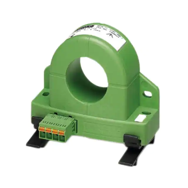
Universal current transducer
Data sheet
104059_en_05
1
© PHOENIX CONTACT 2011-03-09
Features
Description
MCR-SL-CUC-...-I and MCR-SL-CUC-...-U active current
transducers convert DC, AC, and distorted currents into
standard analog signals.
–
–
–
Electrical isolation of input and output signals
Contact-free measurement of live conductors
Large input signal opening
Output signal: 4 ... 20 mA.
Designation
MCR-SL-CUC-100-I
MCR-SL-CUC-200-I
MCR-SL-CUC-300-I
MCR-SL-CUC-400-I
MCR-SL-CUC-500-I
MCR-SL-CUC-600-I
Input current
0 ... 100 A
0 ... 200 A
0 ... 300 A
0 ... 400 A
0 ... 500 A
0 ... 600 A
Order No.
2308027
2308030
2308043
2308072
2308085
2308098
Input current
0 ... 100 A
0 ... 200 A
0 ... 300 A
Order No.
2308108
2308205
2308302
Output signal: 0 ... 10 V
Designation
MCR-SL-CUC-100-U
MCR-SL-CUC-200-U
MCR-SL-CUC-300-U
Make sure you always use the latest documentation.
It can be downloaded at www.phoenixcontact.net/catalog.
This data sheet is valid for all products listed on the following page:
�MCR-SL-CUC-...-...
2
Table of contents
1
Description.................................................................................................................................. 1
2
Table of contents ........................................................................................................................ 2
3
Ordering data.............................................................................................................................. 3
4
Technical data ............................................................................................................................ 3
5
Safety notes and warning instructions ........................................................................................ 5
6
Block diagram............................................................................................................................. 6
7
Structure ..................................................................................................................................... 6
8
Mounting ................................................................................................................................................................... 6
9
Installation ................................................................................................................................................................ 7
9.1
9.2
Power supply.................................................................................................................................................. 7
Connecting the cables.................................................................................................................................... 7
10 Current monitoring ...................................................................................................................... 7
104059_en_05
PHOENIX CONTACT
2
�MCR-SL-CUC-...-...
3
Ordering data
Products
Description
Type
Order No.
Pcs./Pkt.
Universal current transducer for measuring DC, AC, and distorted currents,
0 ... 100 A input current, 4 ... 20 mA output current
MCR-SL-CUC-100-I
2308027
1
Universal current transducer for measuring DC, AC, and distorted currents,
0 ... 200 A input current, 4 ... 20 mA output current
MCR-SL-CUC-200-I
2308030
1
Universal current transducer for measuring DC, AC, and distorted currents,
0 ... 300 A input current, 4 ... 20 mA output current
MCR-SL-CUC-300-I
2308043
1
Universal current transducer for measuring DC, AC, and distorted currents,
0 ... 400 A input current, 4 ... 20 mA output current
MCR-SL-CUC-400-I
2308072
1
Universal current transducer for measuring DC, AC, and distorted currents,
0 ... 500 A input current, 4 ... 20 mA output current
MCR-SL-CUC-500-I
2308085
1
Universal current transducer for measuring DC, AC, and distorted currents,
0 ... 600 A input current, 4 ... 20 mA output current
MCR-SL-CUC-600-I
2308098
1
Universal current transducer for measuring DC, AC, and distorted currents,
0 ... 100 A input current, 0 ... 10 V output voltage
MCR-SL-CUC-100-U
2308108
1
Universal current transducer for measuring DC, AC, and distorted currents,
0 ... 200 A input current, 0 ... 10 V output voltage
MCR-SL-CUC-200-U
2308205
1
Universal current transducer for measuring DC, AC, and distorted currents,
0 ... 300 A input current, 0 ... 10 V output voltage
MCR-SL-CUC-300-U
2308302
1
Accessories
Description
Type
Order No.
Pcs./Pkt.
Flat zack marker strip marking material (without color print, white)
ZBF10:UNBEDRUCKT
0044187
1
DIN rail adapter for mounting the universal current transducer
PACT MCR-RA
2277598
12
4
Technical data
Input
Nominal input current IIN
Overload capacity
Nominal input current IIN
Overload capacity
Nominal input current IIN
Overload capacity
MCR-SL-CUC-100-I
MCR-SL-CUC-200-I
0 … 100 A
0 … 200 A
0 … 300 A
6 x IIN, maximum
3 x IIN, maximum
3.33 x IIN, maximum
MCR-SL-CUC-400-I
MCR-SL-CUC-500-I
MCR-SL-CUC-600-I
0 … 400 A
0 … 500 A
0 … 600 A
2.5 x IIN, maximum
3.6 x IIN, maximum
3 x IIN, maximum
MCR-SL-CUC-100-U
MCR-SL-CUC-200-U
MCR-SL-CUC-300-U
0 … 100 A
0 … 200 A
0 … 300 A
6 x IIN, maximum
3 x IIN, maximum
3.33 x IIN, maximum
Frequency range
DC, 20 … 6000 Hz
Signal form
Connection method
Output
Output signal IOUT
MCR-SL-CUC-300-I
Any
Through connection of 32 mm ∅
MCR-SL-CUC-...-I
MCR-SL-CUC-...-U
4 … 20 mA
0 ... 10 V
Maximum output signal
< 25 mA
< 14 V
Load
< 300 Ω
≥ 10 kΩ
Connection method
104059_en_05
FKCN 2.5/ 4-ST COMBICON connector
PHOENIX CONTACT
3
�MCR-SL-CUC-...-...
Connection data
Outside diameter of input
32 mm Ø
Power supply/output conductor cross-section
Solid (minimum/maximum)
0.2 ... 2.5 mm2
Stranded (minimum/maximum)
0.2 ... 2.5 mm2
Stranded with ferrule without plastic sleeve (minimum/maximum)
0.25 ... 2.5 mm2
Stranded with ferrule with plastic sleeve (minimum/maximum)
0.25 ... 1.5 mm2
AWG/kcmil (minimum/maximum)
24 ... 14
Stripping length (power supply/output)
10 mm
General data
Supply voltage
24 V DC
Supply voltage range UB
20 ... 30 V DC
Current consumption
MCR-SL-CUC-...-I
MCR-SL-CUC-...-U
30 mA + IOUT
30 mA
Power consumption
At UBmax = 30 V and IOUT = 25 mA
1.65 W
Transmission error
Under nominal conditions (25°C)
Linearity error
< ±1% of range final value (IN)
< ±1% of range final value (IN)
Temperature coefficient
0 … 60°C
-40 … 65°C
Step response (90% of IN)
±3.2 µA/K
±6.4 µA/K
150 ms
Ambient temperature range
Operation
Storage
-40°C ... +65°C
-40°C ... +85°C
Safe isolation according to EN 61010
Rated insulation voltage
300 V AC
Test voltage
Input/output
Input/power supply
3.5 kV, 50 Hz, 1 min.
3.5 kV, 50 Hz, 1 min.
Surge voltage category (measurement category according to EN 61010)
III
Pollution degree
2
Degree of protection
IP20
Dimensions (W x H x D)
90 mm x 70 mm x 33.8 mm
Housing version
Frianyl B63 V0 GV30
The current transducer housing meets the requirements of
UL94-V0 regarding inflammability characteristics.
Approvals
UL, USA / Canada
(does not apply to 2308085, 2308098)
Conformance with EMC Directive 2004/108/EC and Low Voltage Directive 2006/95/EC
EMC requirements regarding noise immunity and noise emission
EN 61326-1:2006
General requirements regarding electrical safety
EN 61010-1:2001
104059_en_05
PHOENIX CONTACT
4
�MCR-SL-CUC-...-...
Dimensions (nominal sizes in mm)
90
71,2
10
25
16
6
70
4,6
Ø32
5
33,8
4,6
12,5
78
Safety notes and warning
instructions
Installation and startup must only be carried out
by qualified electricians. When installing and
operating the device, the applicable safety
directives (including national safety directives),
accident prevention regulations, as well as
general technical regulations, must be observed.
In terms of these operating instructions, qualified
personnel are electricians or persons with
electrotechnical training as defined in VDE 0105
Part 1/DIN EN 50110-1.
WARNING:
Disregarding this warning may result in damage
to equipment and/or serious personal injury.
NOTE:
Safe and error-free operation of this device can
only be ensured if transport, storage, and
assembly are carried out correctly and operation
and maintenance are carried out with care.
104059_en_05
PHOENIX CONTACT
5
�MCR-SL-CUC-...-...
6
Block diagram
ADC
IN
8
DAC
µC
Figure 1
I
GND
1.3
NC
1.2
OUT I
1.1
+24 V DC
1.4
GND
1.3
OUT U
1.2
NC
1.1
+24 V DC
Block diagram for current output
ADC
IN
DAC
µC
Figure 2
7
1.4
Mounting
U
PACT MCR-RA
A
B
Block diagram for voltage output
Structure
1
Figure 4
Mounting
The current transducers can be snapped onto all 35 mm DIN
rails according to EN 60715 using the two
PACT MCR-RA DIN rail adapters provided.
Alternatively, the current transducers can also be wallmounted using the fixing holes (see Figure 3, "Structure").
4
3
4
Please use appropriate mounting material for this
(e.g., M4 x 20 cylinder head screw).
Mounting material for wall mounting is not
supplied as standard.
2
3
Figure 3
1.
2.
3.
4.
5.
5
The requirements for the protection class must be
met by means of installation in suitable housing.
Structure
Input cable feed-through for the primary live conductor
Standard output signal and supply voltage
(FKCN 2,5/ 4-ST COMBICON connector)
Connection option for DIN rail adapter
Fixing holes for wall mounting, Ø 4.5 mm
Marking option with flat zack marker strips
104059_en_05
PHOENIX CONTACT
6
�MCR-SL-CUC-...-...
9
Installation
9.1
Power supply
10
Current monitoring
Passive control system
WARNING: Danger
Never carry out work when mains voltage is
present.
4...20mA
Power supply via the connection terminal blocks
–
Power is supplied to the current transducers via connection
terminal blocks 1.1 and 1.4 (see Section 6 "Block diagram",
Figure 1).
9.2
+24VDC
MCR-SL-CUC-...-I
L1
Connecting the cables
Spring-cage connection
The supply voltage and standard output signal are
connected using the spring-cage connection method.
1.4
1.3
1.2
1.1
L2
L3
:
Figure 6
Current monitoring
A
B
Figure 5
•
•
Spring-cage connection
Insert a screwdriver into the opening above the
connection terminal block.
Insert the wire into the corresponding connection
terminal block.
104059_en_05
PHOENIX CONTACT GmbH & Co. KG • 32823 Blomberg • Germany
www.phoenixcontact.com
7
�